
Abstract
Background
Auxetics, a special class of materials, tend to expand both in the radial and longitudinal directions when a unidirectional tensile force is applied. Recently, studies have come up with new designs for auxetic vascular and nonvascular stents which are deployed with commercial balloon catheters. There are some inherent limitations associated with a unidirectional application of expansion force in the effective deployment of stents. This work proposed a solution to some of these limitations through the use of a biaxial mode of a predetermined strain-based expansion mechanism.
Method
The design incorporated a pressure-activated crank-slider mechanism. Fabrication of a prototype for experimental verification was carried out through milling and high-speed lathe machining. The testing of the device employed the use of auxetic stents, fabricated from a biocompatible polymer. A finite element study is presented to extrapolate experimental results to a broader range of operation and working conditions.
Results and Conclusions
The expansion mechanism is similar in operation to the opening of an umbrella. The length of the connected auxetic stent increases when internal hydraulic pressure is applied. The degree of linear expansion in 1 direction influences the expansion of auxetic stent in the lateral direction. As the device exerts pressure longitudinally, a larger amount of the force is distributed on the unit cells/hinges which ultimately results in an increased expansion of the stent.
Introduction
The intravascular stent saw its first practical implantations in the 1980s as a solution for alleviating the risk of restenosis: one of the primary limitations of balloon angioplasty. This form of percutaneous coronary intervention has long since evolved into a much more established procedure; and is currently being used to maintain open passageways in various anatomical regions. The risk of restenosis, however, still remains and affects roughly 20% of all patients subjected to endovascular prostheses. Some recent reports question the establishment of long-term survival rates of stents and the prevention of late thrombosis (1, 2). Effective solutions for the prevention of these complications are being actively sought out and in the process a large number of stent mechanical models have been developed. Dumoulin and Cochelin (3) employed an Finite Elemental Analysis (FEA) model to study the long-term behavior of stent structure expansion. Marrey et al (4) predicted the fatigue life for cobalt-chromium stents through a damage-tolerant fracture mechanics approach (5); the selection of stent materials based on favorable properties of strength, reliability and biocompatibility was also studied (6). The study presented in this article briefly revisited the development of conventional models for stents and extrapolated the ideas developed to a specialized class of meta materials, namely auxetics. Auxetics are classified as materials or structures that exhibit the unique property of simultaneous longitudinal and radial expansion (or contraction) on the application of a uniaxial tensile (or compressive) force (7, 8, 14). These properties are scale independent and can be replicated for any arrangement in shape, size or form. A study on the mechanical properties and expansion characteristics of tubular auxetic structures was carried out by Gatt et al (9). Auxetic stents can be used as an alternative to conventional stents and pose significant improvements in some cases (10, 11). This creates the possibility for a broad range of stent design alterations that may be introduced to impose a positive influence on preventing thrombosis and neointimal hyperplasia (12-13-14). Analysis on the feasibility of application of auxetic stents has already been made, and a number of favorable properties have been concluded (5). Expansion of balloon catheters for conventional stents is effectively unidirectional – that is, radial only. This removes some degree of freedom in operation that only allows for a reduced component of force if the line of application is not perpendicular to the longitudinal axis of the balloon. A further analysis of the mechanical properties of balloon stenting (through Finite Elemental Analysis), in previous works has revealed two major drawbacks: end flaring or dog boning as a function of an increased length of balloon and the bending of stent ends due to under length expansion. Both of these problems prevent the stent from expanding over its full allowable range (15).
The theme of this study was the formulation of a biaxial strain–based expansion mechanism for an auxetic stent. An FEA study of the proposed mechanism was carried out and later complemented by establishing an experimental setup. As opposed to the stress-based expansion of conventional stents, a strain-based approach was proposed, that can be set for any prescribed displacement and works independently of the reaction forces of the target anatomical surfaces. This effectively removes the risk of underexpansion or rupture. Furthermore, a biaxial application of force, feasible only for auxetic stents, adds an additional degree of freedom to the operation of stent placement, since in this case, a longitudinal expansion also accompanies a resultant lateral or radial expansion. We further built on these claims and report on the pros and cons of employing this mechanism as the design considerations are visited in detail.
Materials and Methods
In Silico Design, Device Fabrication and Assembly
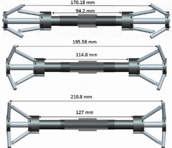
The stent expansion mechanism is basically a pressure-activated slider-crank linkage. The complete device assembly consists of 18 parts. Their connections are described as follows: the spokes were connected via pin joints on one end, having slider parts on both sides which slide over the main rod (Fig. 1). The hollow cylinder was fixed with the main rod. The spokes constitute the crank and connecting rod. The stent contact point is at the leading end of the driven spoke. The main rod has a longitudinal water inlet at one end and a radial outlet exactly at the middle of the rod. To assemble the device as a working mechanism, the cylindrical sliders were placed so as to allow them a translational degree of freedom over the main rod. Spokes (Fig. 1E) were attached to the cylindrical sleeves at an angle of 120° to each other through a pin joint at one end of each of the attachments (Fig. 2). At the other end, the spokes (Fig. 1E) were connected to the fixed cylindrical parts via pin joints. The hollow cylinder (Fig. 1C) was fixed with the main rod forming a closed compartment to allow pressure to build up. Figure 3 shows the complete assembled unexpanded device with water inlet and outlet. Figure 4 shows expanded device with elongation along the radial and longitudinal components.
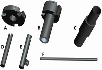
Illustration of different parts of the device: (
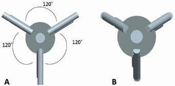
Top view of the device showing the arrangement of the spokes in (
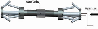
Complete assembled unexpanded device with water inlet and outlet (front view showing water inlet and outlet).
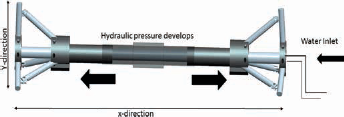
Front view of device showing the relative directions of expansion in radial (y) and longitudinal (x) direction at the application of pressure.
Brass and high-grade aluminum metal was used for fabrication. The parts were fabricated using high-speed lathe and milling machines at the Manufacturing Resource Centre, at the National University of Sciences and Technology (NUST) Manufacturing Resource center (MRC).
To seal the device, O-rings and Teflon tape were used. Two O-rings were connected at the inner surface of sliding part providing sealing between the main rod and cylindrical moving parts; and 2 were attached at the outer surface of the sliding part, sealing the cylindrical moving parts and part hollow cylinder as shown in the Figure 5B.
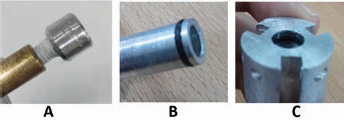
The sealing mechanism: (
Pins were used to connect the spokes to each other and to the parts attached to main rod. Figure 6 shows the complete unexpanded device.
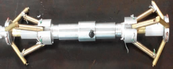
Assembled deployment device.
Testing functionality of the device
To test the deployment device, 2 different geometries of auxetic stents were fabricated (3). The design was cut on a sheet of polyurethane and then folded to form a tubular stent. Polyurethane was selected due to its elastic properties, so that the expansion achieved by the deployment device could easily be recorded.
The first geometry selected for device testing was the rotating squares model (4). The parameters which control the behavior of rotating square design are the 2 angles which are formed at the vertices of joining squares and the constants of hinging and stretching. Apart from these parameters the direction of application of force also plays a major role in overall expansion of the design (Fig. 7).
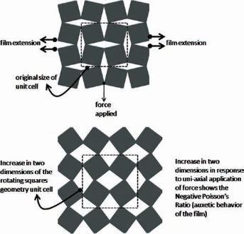
Expansion behavior of the rotating squares auxetic geometry; a uniaxial application of force (in x direction) allows film expansion in both x and y directions.
The second design selected was a rotating triangles geometry (15). A planar view of the film is shown in the schematic (Fig. 8). The unit cells were arranged in a pattern that is repeated multiple times in horizontal and vertical direction. Flexible hinges are the connections between the adjoining unit cells. Hinges between the unit cells and also the vertex angles (shown in detail in Fig. 8), play a crucial part in the expansion of the structure; the measure of the angles B1, B2 and B3 is 137.97°, if the measure of these angles is decreased, the auxetic range achievable by the structure increases. It can be stretched to a greater degree, in both axes (x and y) if uniaxial force (in the x direction) is applied.
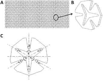
Rotating triangles geometry: (
Fabrication of auxetic stent
Polyurethane PMC-744 (Smooth-On Inc., PA, USA) was used for casting polymeric sheets that were laser cut to achieve the 2 geometries detailed above. PMC-744 parts A and B were mixed in a ratio of 2A:1B and poured into the mold to form sheets that had a thickness of 2 mm.
Rotating squares and rotating triangle auxetic geometries were cut on polyurethane films using a CO2 laser cutting machine. The sheets were then folded to form a circular stent (Figs. 9 and 10). The auxetic stent was mounted on the device to test its expansion mechanism. The expansion of length and diameter were recorded with respect to pressure values ranging from 1 to 4 atm.
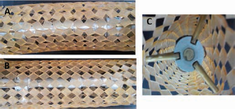
Front view showing rotating square Auxetic stent mounted on device: (
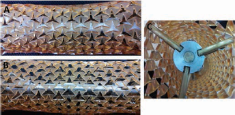
Front view showing rotating triangle Auxetic stent mounted on device: (
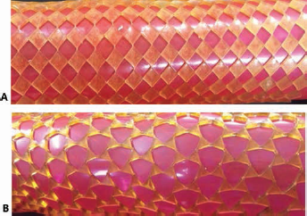
Balloon expansion test
To compare the deployment device results with the conventional method, both the stents (same dimensions) were expanded using conventional balloon catheter methods (Fig. 11). The changes in length and diameter were recorded at the spoke contact point and then compared with experimental results for the deployment device.
(
Numerical analysis
The 2 variables the focus of this study were the magnitude of the force exerted by the spokes on the stent inner surface and the extent of resultant elastic strain induced in the polymer during operation. The former required a 3-stage analysis that included (in order):
an internal fluid flow model to quantify fluid pressure transmittance to the linkage assembly;
the resultant force translation from the sliding cylinder to the spoke-stent contact point;
the internal stresses induced in the stent as a result of the application of above-mentioned force.
Fluid model
A maximum pressure of 4 atm (4.05 × 10⁻⁵ Pa) was applied internally to the pressure compartment in the experimentation process, as discussed later in the “Experimental Results” section. To avoid long computational analysis times, it was assumed that the pressure development on the inside of the pressure compartment was uniform and an even static pressure was exerted on the inner walls of the device during operation. Hence, an application of 4.05 × 10⁵ Pa was approximated and used as the initial condition for subsequent analyses.
Linkage position analysis
The movement of the deployment device from unexpanded to expanded form results in a change in angles and length of the device. The expansion of spokes results in an elongation of the device along the y direction. When pressure is applied, the cylindrical parts move outward causing elongating along the x direction (Fig. 12). The spokes attached to these parts exert pressure onto the spokes attached to fixed cylindrical parts, and they expand in the y direction in a similar fashion to the spokes of an umbrella.
Front view showing the change in lenght from spoke to spoke on expansion of device.
The extent of elongation in the y direction obtained by flexing solely depends on the length of the spokes attached to the fixed cylindrical part. The greater the length of these rods, the greater extension that is achieved; the elongation along the x direction can also be altered by changing the length of the main rod. Thus the length of the rods is the main factor controlling the expansion of the whole mechanism and can be customized according to the requirements and size of the stent.
The linkage employed in the device is a slider-crank mechanism with the water-pressured slider providing the driving force. The crank in this case is limited in its rotation such that the maximum angle of the driven spoke or crank with respect to the longitudinal axis of the base link is 90°. To prevent the mechanism from getting stuck in the folded dead central position, a lower limit of a 25° angle is artificially imposed.
The position analysis of the linkage was carried out to account for the nature of the force being exerted on the stent from the spoke contact point. The initial state of the linkage was set in a contracted position. A displacement range of 65 mm was applied to the slider, and a damper constant of 0.7 with a linear force expression was set to approximate the motion resistance exerted by the fluid surrounding the stent. The results are displayed in Figure 13. A closer inspection of the displacement curves will reveal that the contact point follows a sinusoidal path over its complete range and hence traces a circular curve with a center slightly offset from the pin connection to the cylindrical end plates. This displacement profile offers a smooth and uniform transition between normal and shear stresses to the stent and thereby alleviates the risk of rupture due to abrupt changes in forces.
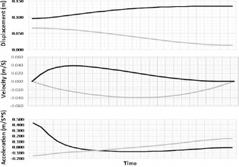
The axial component (grey) and longitudinal component (black) of the positional parameters.
Geometry and discretization
The Initial Graphics Exchange Specification (IGES) file of the auxetic stent geometry was generated in Solidworks version 15, and imported into ABAQUS version 6.14. To get a finite element model, the geometry was discretized using 67, 842 quadratic tetrahedron elements with hybrid formulation (C3D10H). The cylindrical arrangement was obtained by shifting the nodal coordinates from a Cartesian coordinates system to a cylindrical coordinates system.
Material properties
The mechanical behavior of the selected polymer is highly nonlinear. To get a more accurate prediction, a nonlinear material model is recommended. The stent, which was fabricated from polyurethane PMC 744 using a laser cutting technique, undergoes large deformation. To describe the behavior of such material, a first order Mooney-Rivlin isotropic hyperelastic material model (Tab. I) was used (16). The constitutive model curve was plotted from experimental data. Based on the homogenous biaxial stress-strain curve, the material constants were determined with the help of curve fitting techniques in ABAQUS version 6.14; see Equation [1] below:
Hyperelastic material constants for Moony-Rivlin model to describe the mechanical behavior of auxetic stent
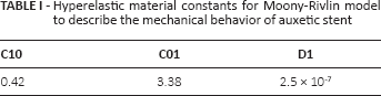

Where U is the strain energy; C10, C01 and D1 are the material parameters; Ī1 and Ī2 are deviatoric strain invariants.
Boundary conditions
The expansion of the stent was achieved using both pressure and displacement driven conditions. Such conditions help to observe the auxetic behavior of the stent. The geometry was constrained in the axial direction, using 8 nodes circumferentially in the mid-section. Another set of 3 nodes in the circumferential direction was defined at both extremes for load application. Next Condition was force-driven on 3 particular nodes on the extremities in corresponding axial and radial directional components at a ratio of 1:3, respectively. These 2 components were summed up in a single direction to get a relation between force and expansion. The computational force was converted into pressure, knowing the piston tip area of the expansion device, which was 100 mm2.
Numerical aspect
To reduce the simulation time, ABAQUS/Standard was employed. As opposed to importing the full configuration and simulating the whole device, which is complex to develop and has a large number of interactions, only the stent geometry was considered. Such interactions not only need long computation times, but are also difficult to converge. The nonlinear effects of large deformation and displacements were turned on, to avoid solution convergence problems.
Results
To save computational times, the simulation was performed only for the rotating squares geometry. A relationship between force application and displacement was established; and an effort was made to validate it experimentally. For this, average values were taken at different nodes (SD = ±5 mm); defined along the stent length, Figure 14a shows such a trend; it can be observed that there is some degree of mismatch between the 2 trends. Such a deviation can be attributed to certain limitations associated with the device operation. The friction between sliding components not only gives rise to a stick-slip condition but also a larger amount of pressure. As a result, the numerical simulation shows higher expansion compared to experimental work for the same amount of pressure of inflation.
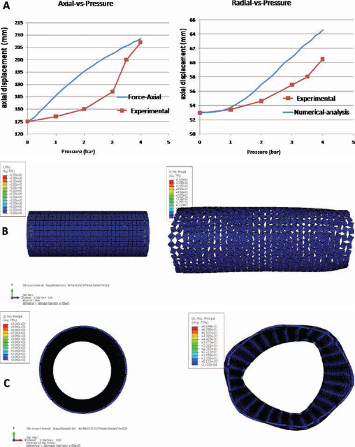
(
Experimental results
An inflation device was used to apply pressure to the device as shown in Figure 4. The auxetic stent was mounted on the device in the contracted (un-actuated) state. Hydraulic pressure was applied, and expansion along the diameter and length was recorded. Three trials were performed using the same stent, and then the mean elongation was calculated. The displacement results are shown in Figure 15.
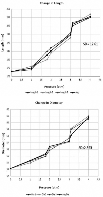
Lenght and diametrical elongation of rotating square geometry stent.
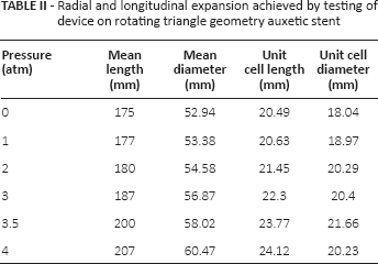
Similarly the auxetic stent with rotating triangle geometry was also tested using the deployment device. The pressure values were kept the same – that is, 0-4 atm. Radial and longitudinal expansion was recorded as shown in Table II. From the graph plotted in Figure 16, it is clear that expansion was achieved both radially and longitudinally.
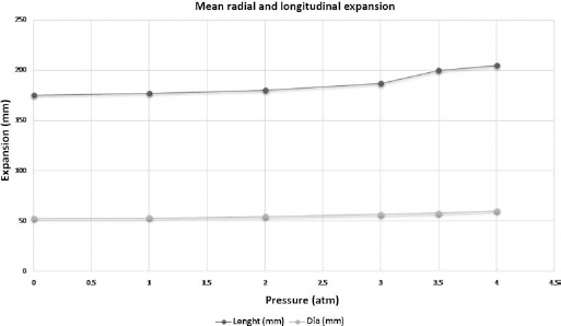
Mean radial and longitudinal expansion of rotating triangles geometry auxetic stent.
Radial and longitudinal expansion achieved by testing of device on rotating triangle geometry auxetic stent
Comparative analysis
To compare the results obtained by testing the deployment device, expansion with a conventional balloon was also performed. Table III shows the comparative analysis of the results obtained for expanding rotating square geometry by both the mechanisms. The initial length of the stent was 175 mm, and on complete expansion with the device, a length of 205 mm was recorded, whereas using the balloon, the length was increased by only 5 mm – that is, from 175 mm to 180 mm. The diametrical expansion was similar for both mechanisms. These results show that there was a significant longitudinal elongation achieved through the umbrella device mechanism.
Comparative analysis of rotating square geometry experimental results versus balloon expansion results
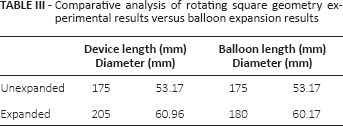
Table IV illustrates the results obtained by expanding rotating triangle geometry using both of the expansion mechanisms. Similar results were obtained as for the rotating square auxetic stent. A significant elongation both radially and longitudinally was observed by expanding the stent using the proposed device, whereas minimal longitudinal elongation was achieved through the balloon. A comparative analysis of expansion results from the 2 mechanisms is highlighted in the plot shown in Figure 17.
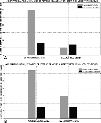
Comparative analysis of changes in stent dimensions when expanded through the novel expansion mechanism and the balloon mechanism; both rotating squares and rotating triangle geometry auxetic stents have been compared.
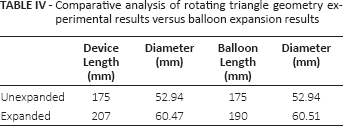
Comparative analysis of rotating triangle geometry experimental results versus balloon expansion results
Simulation analysis
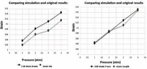
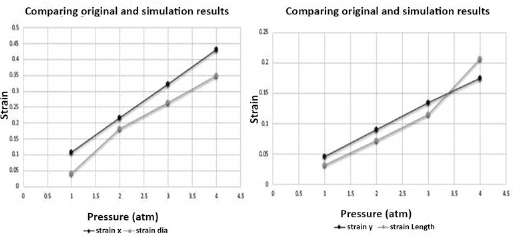
The data obtained through experimental testing of the device was compared through FEA simulation of the auxetic stent. Strain displacement values were plotted along the x and y directions. A comparative analysis was conducted between physical experiments and FEA results for both Rotation-Square and Rotation Triangle geometries was carried out. The strain values of both physical experimental and the FEA testing of both geometries were calculated and plotted as shown in Figures 18 and 19. From the comparative data plotted, it can be established that satisfactory agreement was achieved between the experimental stent expansion and FEA model.
Comparison of simulation along the x-axis and y-axis with the experimentally obtained results for rotating square geometry.
Comparison of simulation along the x-axis and y-axis with the experimentally obtained results for rotating triangle geometry.
Discussion
It is pertinent to mention that this work was carried out as part of a study on a macro-scale model that may be used for deployment of auxetic tubular structures, such as stents. An effort has been made to resolve some of the issues that still plague the balloon catheter method of deployment. The material for balloons in the balloon inflation method may result in lesions being subjected to greater dilation forces at the same amount of pressure. The success of current deployment methods also hinges on the expertise of the clinician's timely termination of applied inflation pressures. We reiterate here that a possible advantage that may be gauged from the results of the present study is that the proposed deployment mechanism can shift the current dependency of stent expansion from a stress-based application to one that is strain-based. In achieving this mode of expansion, the possible risks faced during the stenting procedure that are based on the balloon's shape, material and applied pressure or clinical expertise, can be avoided. This is because in moving toward a strain-based application, the degree of expansion can be precisely predicted; there is less danger of overexpansion of the stent during the procedure, because of the mechanical nature of the deployment device and its predictable functionality.
Current limitations of the proposed device are reflected in some of the discrepancies between the simulation and experimental results. We believe that these may be attributed to increased frictional forces during the actual working of the deployment mechanism and the 3-point contact with the stent during the expansion procedure. These limitations may be addressed in a future study that expands upon the functionality of a similar device with a different material to address frictional force concerns, and a larger number of point contacts with the stent margins that would place less stress on the stent material and hence decrease chances of injury to the vessel wall.
Conclusion
In the current study, we have proposed a macro-model for a deployment mechanism that can potentially be used for the expansion of auxetic tubular structures, such as stents, having a negative Poisson's ratio. According to preliminary data reported in this study, uniform expansion is achieved both radially and longitudinally which may be considered as an advantage over the balloon catheter mode of stent deployment, as the device exerts pressure longitudinally so that force is applied on a larger number of unit cells/hinges, which results in overall expansion. Our initial comparative analysis of experimental and FEA results shows coherence of expansion along both the x and y directions.
Footnotes
Financial support: No grants or funding have been received for this study.
Conflict of interest: None of the authors has any financial interest related to this study to disclose.