
Abstract
Intramuscular cell transplantation in humans requires so far meticulous repetitive cell injections. Performed percutaneously with syringes operated manually, the procedure is very time consuming and requires a lot of concentration to deliver the cells exactly in the required region. This becomes impractical and inaccurate for large volumes of muscle. In order to accelerate this task, to render it more precise, and to perform injections more reproducible in large volumes of muscle, we developed a specific semimanual device for intramuscular repetitive cell injections. Our prototype delivers very small quantities of cell suspension, homogeneously throughout several needles, from a container in the device. It was designed in order to deliver the cells as best as possible only in a given subcutaneous region (in our case, skeletal muscles accessible from the surface), avoiding wasting in skin and hypodermis. The device was tested in monkeys by performing intramuscular allotransplantations of β-galactosidase-labeled myoblasts. During transplantations, it was more ergonomic and considerably faster than manually operated syringes, facilitating the cell graft in whole limb muscles. Biopsies of the myoblast-injected muscles 1 month later showed abundant β-galactosidase-positive myofibers with homogeneous distribution through the biopsy sections. This is the first device specifically designed for the needs of intramuscular cell transplantation in a clinical context.
Introduction
Transplantation of myogenic cells has several potential applications in the clinics. The most important are the therapeutic management of myopathies (13, 21), urinary incontinence (25), and ischemic cardiopathy (22). Collaterally, transplantation of genetically modified myoblasts is considered promising for the systemic or local delivery of hormones or factors (4, 6, 7, 24).
In the case of myopathies, the therapeutic objectives of myogenic cell transplantation are essentially the restoration of proteins whose genetic deficit causes the disease, and, whenever possible, the restoration of contractile parenchyma in skeletal muscles wasted by a degenerative disorder (13). Two different ways of cell delivery are being explored for the efficient incorporation of the transplanted cells into the recipient muscles: direct intramuscular implantation and intravascular injection (13).
So far, the intravascular delivery demonstrated to be efficient only using a specific type of cells named “mesoangioblasts,” and in animal models of particular muscular dystrophies (11, 12). The experiments with intravascular-delivered mesoangioblasts created logical expectations for their potential future use in the treatment of at least some muscular dystrophies. However, it is too early to ensure that they could be useful in all kinds of muscle illness in which cell transplantation may be helpful, to the point of leaving obsolete the intramuscular delivery of myogenic cells.
Most of the other myogenic cells require so far direct intramuscular delivery to be efficiently incorporated into the recipient's muscle. This is notably the case of adult myoblasts, the most frequently studied myogenic cells, recently or presently under study in clinical trials in Duchenne (14, 15), fascioscapular (23), and oculopharyngeal (9) muscular dystrophies, as well as in ischemic cardiopathy (22). In addition, other types of myogenic cells more recently reported (sometimes considered as stem cells) derived or not from the skeletal muscle, require intramuscular implantation (1, 3, 8, 26). The main constraint of this route of administration is that the injected cells contribute to muscle regeneration essentially around injection trajectories, a phenomenon that is more evident in large mammals than in mice (13, 21). To compensate this localized fusion, the surgeon needs to perform meticulous equidistant injections, very close to each other, across the whole muscle, delivering the cells homogeneously during each needle withdrawal. This is the method we use in nonhuman primates (10, 16–18) and myopathic patients (14, 15, 19).
However, such a careful percutaneous cell injection strategy is a slow task when done with manually operated syringes. In a clinical context, it is appropriate only for small volumes of muscle (14). Applied throughout large volumes, the method is very time consuming, becoming strenuous and inaccurate for the permanent necessity of controlling the depth of the intramuscular cell delivery while avoiding cell wasting in the hypodermis. Indeed, this makes difficult to ensure reproducible cell injections throughout a large skeletal muscle, and the patient may endure a long session of injections.
In order to partially alleviate these problems, we previously adapted as cell injection devices some available laboratory dispensers used for the repetitive delivery of small volumes of liquid (18). One of them (a monosyringe dispenser) became so far our instrument of choice for myoblast transplantations in monkeys (10, 18). We also used it for several transplantations in a myopathic patient (15) and it was used by another group in rabbits (2). However, its use in humans remains limited to relatively small regions, and the precision needed to deliver the cells specifically in the muscle through the skin and hypodermis, together with the reproducibility of injections, remains a challenge.
Consequently, we concluded that it would be useful to develop new instruments, specifically designed for the percutaneous intramuscular injection of cells in clinical conditions, covering large muscles in the shortest surgical delays and ensuring reproducibility of injections. We undertook the development of this device according to the following premises: 1) cell delivery through several needles at the same time; 2) cell suspension delivery in very small quantities, homogeneously throughout the needle trajectories; 3) cell delivery specifically in the muscle, avoiding wasting in the skin and hypodermis; 4) minimal frequency of refilling; 5) ergonomics in the conditions of an intramuscular cell injection procedure; 6) easy to clean and to sterilize. We report here the first prototype developed with such characteristics.
Materials and Methods
Device Conception and Fabrication
It was evident that the device needed to be designed on the basis of two parts: a) a circulatory system allowing the progression of a cell suspension from a container to several injection needles, and b) an electromechanical system governing the injection sequence. We denominated the first part the hydraulic circuit, and the electromechanical system the motor block (Fig. 1).

The final prototype is illustrated. The main constituents of the device assembled for use are indicated in (A) (details in Materials and Methods), while (B) shows the different pieces of the hydraulic system, (C) shows the device ready for use, and (D) illustrates the way the prototype is handled during a session of intramuscular cell transplantation in a monkey biceps (the arrow indicates the 27-gauge needle inserted in the container gasket to allow air entry throughout the cell suspension aspiration). A transparent dressing with a 5-mm grid is placed on the surgical region to control the interinjection distance.
It was also evident that the hydraulic system needed some essential components: a cell suspension container, a syringe for injection, several needles, a flow divisor between the injection syringe and the needles, tubing for the circulation of the cell suspension among these parts, and valves ensuring the direction of the flow. Once the principle to place these elements was decided (Fig. 1B), the pieces were sought among those used in clinical liquid management and injection (Table 1). Because these pieces needed to be in contact with the cell suspension, they were mainly of inert plastic. The exception was the injection syringe, made of glass and metal. We considered different cell suspension containers, including standard injection vials, glass cartridges, and disposable syringes, either to be changed or refilled as the cell suspension was delivered. The best and simplest solution was to use a disposable syringe without the piston, leaving the rubber gasket closing the syringe compartment (Fig. 1C and D, Fig. 2A). Our prototype was designed to hold a syringe of up to 6 ml, but could be easily adapted to hold larger syringes. A 27-gauge needle inserted in this gasket (Figs. 1D and 2A) allowed air entry all through the cell suspension aspiration, preventing blocking of the cell suspension flow. This arrangement also allowed refilling the cell container simply by piercing the rubber gasket with a syringe filled with the cell suspension (Fig. 2A). If the operator wanted the air entering the cell container to be filtered, the 27-gauge needle can be plugged with sterile cotton or attached to a 22-μm pore filter.
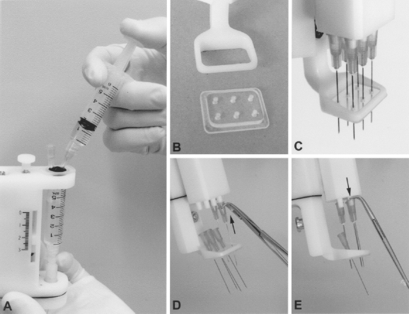
The figure illustrates some practical issues of the device. (A) Shows the way to refill the cell suspension container. The 27-gauge needle placed in the rubber gasket allows air exit during refilling. (B) Shows the plastic removable plate that can be added in the adjustable foot of the device. This plate helps to stabilize the needles (C) and flatten the skin surface. (D, E) Show the way to place and to remove the needles using a haemostatic forceps with curved tips. Needle removing is easier by pushing them with the curved tips of the forceps acting as a lever (E) than pulling them. The removable plate facilitates this task by maintaining the needles close to the tips before inserting them (D), and by receiving the removed needles (E), avoiding risks of injury.
Elements and Suppliers Used

The device was designed to use up to six standard disposable needles, forming a matrix of 2 × 3. Placed as close as possible, the needle are separated by ~8 mm. To use fewer than six needles, the nonused tips can be plugged with appropriate stoppers. The capacity of the Hamilton syringe to be placed in the device can be chosen according to the number of needles to be used and the cell suspension volume to be delivered per injection trajectory (Table 2). Most uses would need 250- and 100-μl Hamilton syringes.
Cell Suspension and Needles Used

We evaluated different mechanical principles to determine an optimal arrangement to control the injection sequence. The principle adopted was based on a small Hamilton syringe injecting the cell suspension and refilling at each injection round. Thus, the device was designed to perform each injection round (penetration/retraction of the needles into the tissues) by moving down and up the glass body of the Hamilton syringe, which is fixed with a screw (syringe fixation in Fig. 1A) to a mobile part in the motor block (mobile support in Fig. 1A). The mobile support, the glass body of the Hamilton syringe, and the needles move as a whole at each injection round (Fig. 3A, B). Syringe and needles are linked by a plastic support that includes the flow divisor and a “T” block connector (Fig. 1B). The piston rod of the Hamilton syringe is fixed to the nonmobile part of the motor block by another screw (piston fixation in Fig. 1A). The down and up movements of the glass part of the Hamilton syringe produce the circulation of the cell suspension from the container towards the needles. When the mobile support moves down for needle penetration, the loading valve allows aspiration of the cell suspension from the container into the Hamilton syringe, while the injection valve prevents reflux from the needles (Fig. 3C). When the mobile support moves up for needle retraction, the injection valve allows the delivery of the cell suspension into the injection trajectory, while the loading valve prevents reflux to the cell suspension container (Fig. 3D).

Motor-driven movements while pressing the pushbutton (A, B) and circulation of the cell suspension during these movements (C, D).
The mobile support is driven by a motor and a lead screw. To adjust the amplitude of this movement to the needs of the cell delivery, a run-end detector is moved down and up through another lead screw, turning a knob indicated as regulator of injection depth in Figure 1A. The position of the run-end detector determines the amplitude of the needle excursion. This knob also moves an indicator of injection depth (Fig. 1A). The incursion of the needles during the injection round can be preset between 0 and 3.5 cm.
The motor is activated by pressing a pushbutton, placed at the bottom for a better handling by the surgeon (Fig. 1A, C, D). When the pushbutton is pressed, the motor is subjected to a voltage of 6 V, rotating clockwise and driving the lead screw through an Oldham coupling. The rotation of the lead screw allows the vertical motion of the mobile support. Because the piston rod of the Hamilton syringe is fixed to the device body, a movement towards the bottom of the glass part of the syringe aspirates the cell suspension into it. The amount of solution aspirated (which will be subsequently injected) is directly proportional to the vertical displacement of the needles. When the mobile support passes in front of the run-end detector, the control chip inverts the voltage applied to the motor, which turns in the opposite direction: the mobile support then moves up. This movement produces the needle retraction and the delivery of the cell suspension in the injection trajectories. Finally, when the mobile support passes in front of the run-start detector, the control chip cancels the voltage applied to the motor and the motor stops: no movement can then occur given the self-locking nature of the lead screw. To restart the sequence, the pushbutton must be released and pressed again. All motion is controlled by the logic circuit included in the control chip (designed by Yves Jean and assembled by Michel Dominique, Department of Mechanical Engineering, Laval University). To make the device as light as possible, we decided to use external power supply. The device is thus connected to an alternating current power socket when it is used, by means of a class-2 transformer. Plugging is done via a circular electric connector consisting in a cable pin and a panel mount placed in the back of the device, near the pushbutton (Fig. 1A, C, D).
An adjustable foot (a frame that surrounds the needles) is placed at the bottom of the device. This part is to be in contact with the skin, allowing: a) setting up the preinjection distance of the needles and b) serving as a support during the injection (Figs. 1D and 4). It can be moved vertically between 0 and 15 mm, and fixed with a screw, in such a manner that the distal length of the needles in the resting top position corresponds with the distance needed to reach the muscle surface from the skin surface (Fig. 4A, B). This distance must be determined preoperatively by ultrasound analysis (Fig. 4A). A removable plate made of transparent plastic, with six holes corresponding to the six needles, can be fixed by pressure in the frame of the adjustable foot (Fig. 2B, C). This plate allows a) to stabilize the needles during the manual introduction and the motor-driven penetration of the needles in the tissues (Fig. 4B, C), and b) to flatten the skin surface that otherwise can make a bulge into the frame. It also facilitates the insertion of the needles in the device, because the needles can be placed first in the plate and approached close to the tips before inserting them (Fig. 2D). It also facilitates to remove the needles that can be collected in the plate before being securely discarded (Fig. 2E).

The operation of the device is illustrated. According to an ultrasound analysis of the region to be injected (A), the operator sets the adjustable foot to leave the needle length necessary to go through the skin and hypodermis, and sets the incursion distance of the needles into the muscle by turning the regulator of injection depth. The operator introduces the needles until the device's foot touches the skin surface (B). At that moment, the needles' tips may be placed at the muscle surface. Pressing the pushbutton (arrowheads), the needles penetrate the muscle (C) and the syringe is filled with the cell suspension. Once the needles reach the depth of injection (C), they are automatically retracted to their original position and stop (D). The cells are homogeneously delivered during this retraction (D). The operator withdraws manually the needles (E) and restarts the sequence following the planned interinjection distance. Arrows indicate the manual (gray) and motor-driven (black) movements.
In order to verify the concept and to guide the design, we performed simulations with the following software: Pro/ENGINEER (PTC, Needham, MA) for the 3D modeling and Matlab (MathWorks Inc., Natick, MA) for the mathematical computation. Some pieces of the device were specifically manufactured, while others were purchased from different suppliers (Table 1). Material for the plastic pieces supporting the mechanism and the hydraulic system was bought at Plastique Polyfab Inc. (Quebec, QC, Canada) and then manufactured by Yvon Chalifour, from Electrotechnologies SELEM Inc. (Quebec, QC, Canada). Metal pieces such as specific screws were machined in the workshop of the Department of Mechanical Engineering at Laval University.
Measurements and Calculations
Because the device had to be as light as possible, one of the most important criteria in the choice of the mechanical components was the power-to-weight ratio. The critical components were some pieces of the hydraulic system (valves and fittings), the motor, and the gearbox. We will describe briefly the calculations made to ensure the proper functioning of these parts.
Power Losses. There were two main sources of power losses to be considered: friction losses in the hydraulic system, and friction between the needles and injected tissues. To quantify these losses, the hydraulic system was filled with a cell suspension and the piston of the Hamilton syringe was pushed with a dynamometer at about 1 cm/s (the desired speed of the system). The maximal load was ~200 g. This corresponded to the force necessary to overcome the friction losses in the hydraulic circuit, as well as the friction of the piston rod in the Hamilton syringe. Similar tests were performed to determine the force needed for the penetration of a needle into a tissue. A silicon bolus of radiotherapy was used in the Robotics Laboratory to simulate the injected tissues (this represented a worst case situation, because this bolus was more resistant than skin and muscle to needle penetration). For an injection speed of ~1 cm/s, the maximum measured force was 500 g.
Hydraulic System. The pieces of the hydraulic circuit are restrictive for pressure. To avoid leakage at the fittings, pressure must not exceed 1000 psi. Valves guarantee the absence of reflux for up to 100 psi. The internal pressure of the hydraulic system can be assessed by dividing the maximum force applied to the piston rod by the diameter of the rod. For a 250-μl Hamilton syringe, this was:
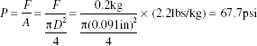
Because the maximum pressure that can be achieved is much lower than the limits of the pieces of the hydraulic system, the system was expected to work correctly.
Motor and Gearbox
Power Losses. The choice of the motor depends on the friction forces to be countered. The motor must overcome the friction of six needles penetrating the muscle (6 × 0.5 kg = 3 kg), as well as the friction losses in the hydraulic system (200 g). The sum of the two, with a safety factor of 2, gives a maximum external force to counter of 6.4 kg or 62.8 N (14.1 lbs).
Torque. The sum of these external forces is exerted on the mobile support, which progresses through a lead screw (16 threads per inch) using a Supernut®. The couple Td to be applied to this screw to generate a force of 14.1 lbs was calculated taking into account the force P, the thread of the screw L, and the efficiency hf of the Supernut®:

Rotational Speed. The rotational speed wd of the motor (for a given torque) depends on the range of motion dx of the mobile block, the time t required for this movement, and the thread L of the screw:

Therefore, for trajectory times ranging from 1 to 1.5 s, the desired speed of the motor must be between 252 and 378 rpm.
Selection of Motor, Gearbox, and Control Chip. These calculations were used to choose a combination motor/gearbox/chip appropriate for the required performance in terms of torque and speed of operation. Their most important characteristics are presented in Table 3. From this table it can be noted the following.
Characteristics of the Motor, Gearbox, and Control Chip

In order to avoid excessive heat, the maximum current from the chip Ichip is selected to be equal to the continuous current of the selected motor Icont. Then, the maximum torque of the motor/gearbox/chip block is: Tmax block = Tcont mot × rgearbox × hgearbox = 0.061 Nm). The expected torque (Td = 0.033 Nm) is sufficiently lower than the latter torque.
The maximum torque of the motor/gearbox/chip block (Tmax block = 0.061 Nm) is sufficiently lower than the maximum torque that can be sustained by the gearbox (Tmax gearbox = 0.225 Nm).
The chip voltage (Vchip = 6 V) is selected as half the nominal voltage (Vnom = 12 V) in order to obtain a speed of the motor, which is half the no-load speed (wempty mot = 13900 rpm). With the selected gearbox ratio, the resulting speed of the motor/gearbox/chip block is: wempty block = (wempty mot/2) × (1/rgearbox) = 366 rpm, which is in the desired range of speed.
Half of the no-load speed (6950 rpm) is below the allowable limit at the gearbox input (winput = 8000 rpm).
It can be shown that the run speed of the mobile support is 0.97 cm/s (@366 rpm) if no force is applied, and 0.83 cm/s if the external force reaches the maximum value Td = 0.033 Nm (@312 rpm). The injector will have then a speed of operation around the desired value of 1 cm/s.
In Vivo Tests in Nonhuman Primates
We tested the device performing intramuscular myoblast allotransplantations in six adult cynomolgus monkeys (Macaca fascicularis). The two first monkeys were used to practice the technique of injection and to plan adjustments in the device, while the other four monkeys were used to quantify the results of the transplantation. The use of the device was innovative, but the rest of the procedure was similar to our standard transplantation protocol in monkeys (16–18). Briefly, transplantations and biopsies were done under general anesthesia with isofluorane. Ketoprofen was given for postoperative analgesia. Tacrolimus (a generous gift from Fujisawa Pharmaceutical Co., Ltd., Osaka, Japan) was used for immunosuppression. Euthanasia was done in two monkeys by intracardiac overdose of sodium pentobarbital after ketamine anesthesia. All procedures were authorized by the Laval University Animal Care Committee.
Myoblasts from muscle biopsies were grown in MB-1 medium with 15% fetal bovine serum (Valley Biomedical, Winchester, VA) and 10 ng/ml of basic fibroblast growth factor (Wisent, St-Bruno, QC, Canada). They were infected in vitro with a retroviral vector encoding the LacZ gene (gift from Dr. C. Cepko, Harvard University, Boston, MA). For transplantations, the cells were resuspended in a balanced salt solution into a 10-ml vial. The cell suspension container in the device was filled with the content of these vials. Transplantations were done throughout one biceps brachii by parallel cell injections, trying to maintain 1 mm of distance between each other. In one monkey, myoblast transplantations were done in two other sites using either a manually operated 50-μl Hamilton syringe (16) or a PB600-1 repeating dispenser with a 250-μl syringe (18). Although different instruments were used, the transplantation parameters (cells, interinjection distance, amount of cells per injection, needle size) were similar.
One month posttransplantation, we took samples of the cell-transplanted muscles of the monkeys. Euthanasia was done in one monkey to sample the entire biceps brachii. Muscle samples (including a whole biceps brachii) were mounted in embedding medium, frozen in liquid nitrogen, and serial sections of 10–15 μm were made in a cryostat. β-Galactosidase-positive myofibers were revealed in the muscle sections with X-Gal, as previously described (5) and analyzed in a microscope.
Cell suspensions were also prepared for ex vivo tests (i.e., evaluation of the cell mortality after passage through the device and evaluation of the cell suspension distribution among the six needles). For both transplantations and ex vivo tests, the cell suspension concentration was between 28 × 106 and 57 × 106 cells/ml (i.e., over the optimal for myoblast transplantation experiments in monkeys, which is about 20 × 106 cells/ml for the injection parameters used).
Results
The final prototype performed well and reached the objectives set out before the design, essentially as indicated below.
The device can deliver a cell suspension through six needles (or fewer if desired) at the same time. By testing the device ex vivo, the volume of liquid delivered per needle was equivalent (Fig. 5). This was similar when using only water or a cell suspension at the standard concentration used for an optimal transplantation. It was impossible to quantify the volume delivered per needle in vivo, but when reflux of injected cell suspension was produced deliberately there was always a similar drop of cell suspension emerging at each injection point.

Percentage of the total content of the cell suspension container delivered per needle into small tubes, following three tests with either water or cell suspension. Needles were 25-gauge 1.5 inches, and the indicator of injection depth was adjusted at 3 cm; cell suspension concentration was 40 × 106 cells/ml.
The cell suspension circulates well and follows the expected direction and sequence. There is no leakage or air entry at the fittings. The speed of the needles is of around 1 cm/s.
The trypan blue tests performed with the cell suspension before and after passage through the device showed no increase of cell death (1.7% of cell death before passage and 1.9% after passage in one test, and 6% before passage and 5.3% after passage in another test).
The device has a weight of 400 g. It can be comfortably handled during the transplantation session, and can function either in a vertical, inclined, or even horizontal position (provided that air in the cell container does not enter into the hydraulic circuit). The procedure of cell injection was considerably faster, less tiring and more ergonomic than using manually operated syringes.
The muscle samples taken 1 month posttransplantation in the sites grafted with the semimanual device showed β-galactosidase-positive myofibers homogeneously distributed throughout the muscle sections, and sometimes better than in sites grafted with manual procedures in the same monkey (Fig. 6A, B). The transplantation success (51–63% of β-galactosidase-positive myofibers in the muscle cross-sections) was in the superior region of the range obtained with our manual procedures (Fig. 6C).
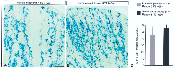
Results of transplanting β-galactosidase-labeled myoblasts in monkeys, using our manual techniques versus the semimanual device. Two cross-sections of biceps brachii biopsies obtained 1 month posttransplantation in a monkey and histochemically treated to reveal β-galactosidase-positive (β-Gal+) myofibers are illustrated (A, B). The main transplantation parameters were similar in both sites (cells, interinjection distance, amount of cells per injection, needle size) but injections were done either manually using a repeating dispenser with a Hamilton syringe or with the semimanual device. The semimanual device gave in this case more homogeneous results in terms of density and distribution of β-galactosidase-positive myofibers. The arrow on the left indicates the direction of the cell injection trajectories. Scale bar: 1 mm (applies to both images). (C) The graphic shows a comparison of the results obtained in the four monkeys grafted here with the semimanual device, and a pool of 14 results obtained here or previously in monkeys grafted manually, using similar parameters of transplantation (needle size, interinjection distance, optimal amounts of cells, appropriate immunosuppression).
Practical Considerations
The device needs to be properly set up prior to each transplantation session, which requires being familiar with the sequence of preparation. This includes filling the dead space of the hydraulic circuit with saline solution before loading the cell suspension, to ensure that no bubbles remain within and that liquid circulation is appropriate. A bubble remaining in the plastic hub of a needle was sometimes enough to block liquid delivery through this needle during tests ex vivo, although apparently not during in vivo injections. Then, when the cell suspension is loaded in the container, the operator needs to perform several injection rounds ex vivo to allow the cell suspension to replace the saline solution into the hydraulic circuit. The tubing in the hydraulic system is transparent and allows observing the progression of the cloudy and colored cell suspension pushing the hyaline saline solution. The dead space of the hydraulic system, from the tip of the cell suspension container until the tips of the injection needles (excluding the Hamilton syringe) is of roughly 1 ml.
In addition, some training is needed to properly place the device at each injection round to reach a homogeneous cell delivery throughout the muscle.
Some cell sedimentation can occur in the cell suspension container during transplantation. To resuspend the cells, it is sufficient to tilt the device allowing the air into the cell suspension container to form a bubble stirring the liquid by its passage.
Pauses during transplantation may be essentially to refill the cell suspension container and to change the needles. Refilling must be done while there is still some cell suspension into the container to avoid passage of air into the hydraulic circuit. Thus, the surgeon must monitor the level of liquid into the container. Refilling is rapid and easy (Fig. 2A). We performed cell injections throughout monkey biceps without changing the needles, but this may be needed in larger surfaces. To avoid accidental injury, the needles can be detached and placed using haemostatic forceps, preferably with curved tips (Fig. 2D, E). Removing the needles is faster and easier by pushing them from the tips than pulling them (Fig. 2E).
Safety Issues
To complete the injection round, the pushbutton needs to be maintained pressed. Releasing the button stops the needle movement in the case of an undesired event. The needle movement can then be resumed by pressing the same button.
Cleaning and Sterilization
The hydraulic circuit can be easily detached from the motor block and disassembled for appropriate cleaning and sterilization. All the pieces of the hydraulic circuit can be immersed in disinfectant solutions. Pressure air is useful to dry these pieces before sterilization. With the exception of the device's foot (that can be detached) the motor block cannot be immersed, but its plastic surface can be cleaned with gauze soaked in a disinfectant solution. All components can be sterilized with ethylene oxide.
Discussion
We described a first device specifically designed to perform repetitive percutaneous intramuscular cell injections throughout large skeletal muscles. This device was designed to solve some of the most important problems encountered in our clinical practice of intramuscular cell transplantation. After years of experience on myogenic cell transplantation in nonhuman primates (16–18, 20), and following our recent human tests (14, 15, 19), we concluded on the importance of creating specific instruments for this task, allowing efficient cell transplantations throughout large skeletal muscles in the shortest surgical delays.
We analyzed different mechanical principles for this device. A first principle was based on the repeating dispenser that we used for myoblast transplantation in nonhuman primates and in a patient (10, 15, 18). The idea was then a device holding a large Hamilton syringe, refilled entirely from a cell suspension container, and empting its content progressively at each injection round, a pause being needed to refill the syringe before continuing with the next series of injections. This idea was abandoned for the present design, in which a smaller Hamilton syringe delivers the cell suspension and refills at each injection round, until the cell suspension container is empty. This design has some advantages over the former, namely: a) the overall mechanism was simplified; b) the cell suspension circulates continuously, helping to avoid cell sedimentation in the tubing, connectors and valves, as could happen during the long pauses between refillings required for the first design; c) interruptions of the injection sequence are less frequent (only to refill the cell suspension container or to change the needles).
The term ‘semimanual” was used to define our device because the needle penetration and withdrawal through the skin and hypodermis is performed by the surgeon, but the penetration and retraction of the needles into the skeletal muscle, together with the intramuscular cell delivery, is performed by the device by pressing the pushbutton.
Essentially, the advantages of the present device for intramuscular cell transplantations in a clinical context are the following: 1) Using more than one needle at the same time accelerates the procedure. 2) Because the length of needle penetration required to reach the muscle and the length of cell delivery into the muscle can be preset in the device, the operator needs only to be focusing on positioning the needles at each injection round. 3) The intramuscular course of the needles and the accurate cell delivery are performed automatically by pushing a button. 4) All the content of the cell suspension container (up to 6 ml in our prototype) can be delivered without interruption, reducing the frequency of pauses for refilling. Refilling of the cell suspension container is easy and quick. 5) The cell injections are more reproducible in terms of needle penetration, intramuscular homogeneous cell delivery, and amount of cell suspension delivered per injection, avoiding the variables, imprecision, and potential errors of a purely manual procedure.
In conclusion, the device reaches most of our expectancies, although there is probably some room for improvement. We also believe that this device could set a standard for the further development of other cell injection tools, and even for the potential development of more complex robotic equipment able to make cell injections automatically, ideally through a stereotaxic system using the guidance of medical imaging. Moreover, our device could be also useful for cell transplantation in the myocardium or for intramuscular repetitive injections of gene vectors in a clinical context.
Footnotes
Acknowledgments
This work was supported by grants from the Association Française contre les Myopathies (AFM, for the development of the device) and the Jesse's Journey Foundation for Gene and Cell Therapy of Canada for monkey experiments. The idea of the device, the premises for its design, and the in vivo tests correspond to D.S. P.L.R. was responsible for developing the device under the supervision and suggestions of C.G. and T.L.; P.L.R., C.G., and T.L. designed the principle of the device. Jacques P. Tremblay is a major stockholder in CellGene Inc., a biotechnology company created to accelerate the development of various cell therapies.