
Abstract
Motion errors can significantly affect the machining accuracy of MACNC. To reduce the motion errors in the operation of CNC, an error compensation algorithm is proposed in the study. Firstly, the motion error measurement and identification method is proposed, and in this way, the MECA based on the third spline fitting is proposed Finally, the effectiveness is verified by simulation experiments. The proposed error measurement method has high measurement accuracy, and the MECA can effectively reduce the machining error value, and its processing time is only 0.012s. The measurement accuracy of the error measurement method proposed in the study reached 98.95%, which was 4.49% and 4.88% higher than the minimum measurement accuracy based on wavelet denoising and genetic algorithm, respectively. When the number of iterations was 5, all three measurement methods achieved the minimum measurement accuracy, and the minimum measurement accuracy of the proposed measurement method was 91.00%, Compared with the minimum measurement accuracy of 93.65% and 94.26% based on wavelet denoising and genetic algorithm, it has decreased by 2.65% and 3.26%, respectively. When disturbed, the accuracy rate of the error compensation algorithm proposed by the research is 93.9%, which is 2%, 2% and 3.5% higher than the minimum values of 91.9%, 91.9% and 90.4% of the three error compensation algorithms based on BP neural network, Particle swarm optimization algorithm and genetic algorithm, respectively. The above results show that the MECA can effectively achieve the error compensation of MACNC, with a fast processing speed, which can effectively workshop Machining efficiency and quality.
Introduction
With the development of industrial automation, CNC machining has gradually become the main way of precision machining of workpieces. Due to the demand for high precision and efficiency of workpieces, the new generation of CNC machining systems has been developing toward the higher efficiency and precision [1]. However, most of the control methods currently used in engineering are following error control, which improves accuracy by shortening the distance between the actual and desired positions. This leads to the inability of CNC machining to fundamentally reduce errors to achieve high speed and high accuracy machining [2, 3]. In addition, with the gradual and widespread application of Multi-axis CNC (MACNC), a large number of studies have begun to explore their machining error control methods. However, the compensation effect shown by a large number of existing error compensation algorithms is not ideal [4]. Previous studies have concluded that the main factor affecting the machining accuracy of machine tools is the motion error. For this reason, the study has proposed error measurement and compensation methods to improve the efficiency of MACNC, taking the machine tool motion error as the research object. This also can ideas for the development of MACNC. In order to provide theoretical basis for subsequent error compensation and precision design, topological structure analysis and low order body array description of three-axis CNC milling machine based on multi-body system theory were studied, and the feature matrix among the machine tools was listed using the principle of Homogeneous coordinates transformation. According to the relative pose relationship between the cutter and the workpiece, a comprehensive Transitive model of spatial geometric error of three-axis CNC milling machine was established; Based on the screw theory, an error model that can directly separate the compensatable and non compensatable error sources is established. Based on the established comprehensive error Transitive model of the machine tool, the software error compensation methods of three basic motion modes of the three-axis NC milling machine are analyzed respectively.
Related work
MACNC are important equipment in intelligent production, and a large number of studies have proposed solutions to improve the performance of CNC to enhance the productivity of MACNC. Fang et al. [5] in order to reinforce the model by arranging fine wires along the direction of maximum stress, a new computational framework was proposed to generate tool paths for multi axis printing. The results showed that this method can withstand up to 35 times the load of experimental testing. Liu et al. [6]. The role of machine tools in the manufacturing industry was analyzed. In order to address the current situation of digitization and service-oriented machine tools, a new conceptual framework for information physics machine tools was constructed by combining bibliometric and qualitative analysis methods, and this framework was used as a systematic method to achieve digitalization and service-oriented next-generation machine tools. The results indicate that this method is helpful for researchers and industry practitioners to develop new ideas for the next generation of machine tools in the Industry 4.0 era. Praniewicz et al. [7] proposed a method to push to the motion error of a five-axis machine tool. This method takes the structural error of the machine tool as the object of study and simulates the calculation to derive the error constants through kinematic simulation. The study was able to quickly and correctly calculate the error of the multi-axis machine tool and use it to compensate the error of the machine tool and improve the machining accuracy of the CNC. Rakic et al. [8] proposed a control method which was studied for the wood processing of the machine tool, using a multi-axis wood CNC Finally, a digital dual control system was developed. The performance analysis of the system showed that the control system proposed in the study is effective and can achieve stable control of MACNC. Chen et al. [9] proposed a method to measure the angular error of CNC. This method takes MACNC as the object of study that, using laser measurement as the principle, the angular error measurement of machine tools is achieved by automatic focusing technology. The measurement method proposed in the study has a high resolution and is of great value in machine tool accuracy improvement.
In the work of CNC, motion error is the main factor that leads to the degradation of its machining accuracy. To improve the motion error prediction capability, Liu et al. [10] proposed a prediction framework based on digital twin and set up prediction experiments to verify the effectiveness of the method. The prediction method proposed in the study can effectively identify the motion errors in CNC and propose a compensation strategy. Vogl et al. [11] used the motion errors of CNC to determine the motion errors of machine tools by analyzing the track wear of CNC. In addition, the study developed an analysis procedure that can determine the location of the damage caused by the motion error as a way to achieve early warning of the error. Esmaeili and Mayer [12] introduced variational kinematics to avoid geometric errors generated in the machining of CNC and by this method a linear gain error compensation strategy can be proposed. In the analysis of the results, it was shown that the method proposed in the study was able to effectively reduce the geometric error of the CNC machine and was able to improve the volumetric error. Zheng et al. [13] proposed a laser measurement method. This method was able to quickly and accurately obtain the geometric kinematic error of the CNC machine, and at the same time developed a measurement system that could be applied in the workshop. The experimental analysis indicated that the method proposed in the study can effectively achieve stable measurement of errors and provide ideas for geometric motion error compensation of CNC. Liu et al. [14] proposed a measurement point selection method to reduce the geometric motion errors of CNC and combined it with simulation software for machining simulation. The measurement point selection method proposed in the study was able to improve the machining accuracy to a certain extent, showing that the machine tool errors were compensated.
In summary, for the workshop machining status, a large number of studies have concluded that reducing the machining error of CNC can effectively improve their machining accuracy. The impact of machine tool motion error is considered to be significant, but few studies have proposed ideal motion error compensation methods for multi-axis linkage machine tools. Therefore, the study takes MACNC as an example, proposes its motion error compensation strategy, and verifies its effectiveness through simulation, to provide ideas for workshop machining accuracy improvement. The motion error compensation algorithm proposed in this study can effectively reduce the machining error value. Compared with the method proposed by Hong RJ to determine the error by measuring the position of the fixture through sensors, the method proposed in this study has higher detection accuracy and efficiency. And the main conclusions drawn from this research work provide prospects for future research on motion error compensation of CNC machine tools.
MACNC motion error compensation method design
Multi-axis machine motion error modeling
The accuracy of CNC determines the production quality of the workpiece in the workshop. Nowadays, to improve the machining accuracy of CNC, a large number of studies start from the error compensation. In the error compensation of CNC, the first need to establish the machine tool error model, and then calculate the overall error of the CNC [15, 16]. Generally speaking, the motion error of CNC includes workpiece motion error and tool transmission error.
In MACNC, the workpiece motion error generally contains multiple axes. Taking a three-axis machine tool as an example, there are two workpiece motion axes, and the coordinate systems
In Eq. (1),
In Eq. (2),
In addition to the motion error generated by the workpiece movement, in the tool feed, the tool drive error will also affect the motion error of the CNC. In the three-axis CNC in the machining, the tool is generally in the Z axis, based on the error analysis in the workpiece processing motion, the tool position error spin amount is obtained in the Eq. (3).
In Eq. (3),
The matrix form of machine tool motion error is obtained to represent the mapping of error in position and attitude accuracy in Eq. (5).
In Eq. 5),
The motion error measurement of MACNC is the basis of error research, so the study requires accurate measurement and identification of the motion errors of the machine tools in the error modeling [17]. To improve the accuracy of error measurement in the study, a laser interferometer system is introduced to achieve positional and geometric accuracy. The error measurement is shown in Fig. 1.
Motion error measurement process.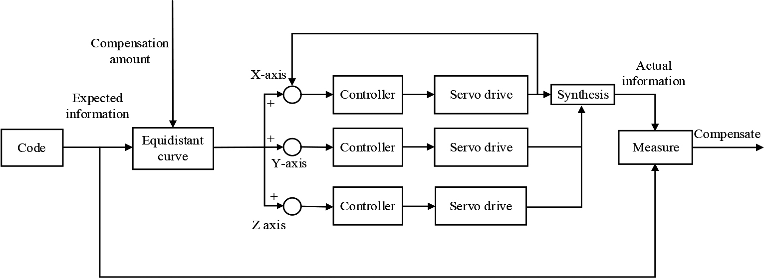
In Fig. 1 it is shown that the desired workpiece machining information is input into the CNC machine and the CNC machine starts workpiece machining. During the process, the machine breaks down the machining information into the coordinate system x and y axes and uses this to control the tool motion on the z axis. The controller is used to control the servo motor for machining Finally, the geometric motion information on the three axes is combined into the actual workpiece machining information for that area segment, which is collected by raster measurement and output the final calculated error information. The three perpendicularity errors between the three linear axes X, Y, and Z, namely
Calculation principle of verticality error.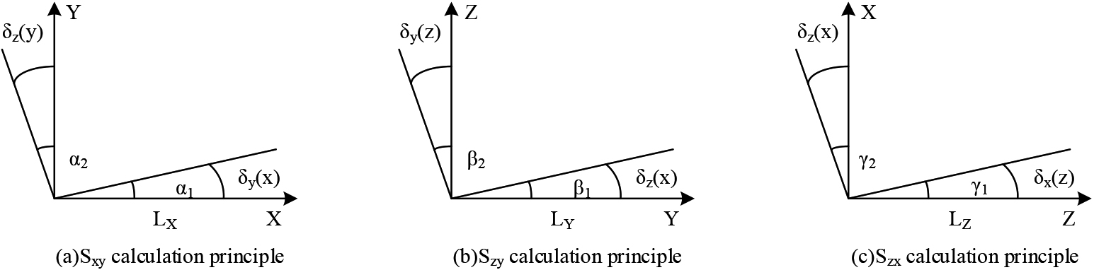
The error separation method is introduced after the error measurement to distinguish the different errors. The the geometric characteristics of the different errors are expressed in Eq. (6) when the workpiece is machined to move mainly in the x-axis.
In Eq. (6),
In Eq. (7), the motion error of the MACNC is analyzed by the motion of the workpiece on the
Finally, through Eqs (6), (7) and (8) to calculate the motion error of the three-axis CNC, it is utilized to analyze the size of the error to facilitate machine error compensation.
The study analyzes the motion errors existing in the operation of CNC through machine tool motion error modeling, and proposes error measurement and identification methods. Thereafter, the error compensation algorithm is proposed based on the identification results of the motion errors of the MACNC. The error compensation algorithm of the geometric trajectory is studied to eliminate the motion errors generated by the CNC processing, and the error compensation of the MACNC is shown in Fig. 3.
Error compensation process of MACNC.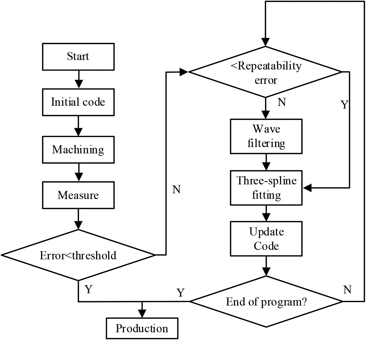
In Fig. 3, it is shown that in CNC processing, the motion error generated by the workpiece processing is obtained by the error measurement method proposed in the study. It is judged whether the obtained error meets the production conditions, and when the error is within the permissible range, the workpiece is directly produced. When the measured error does not meet the production conditions, the measured error value is compared with the repeatability error value. If it is less than the repeatability error, it is not involved in the compensation; If it is greater than the repeatability error, it is filtered to reduce the noise impact to reduce the error of the contour after information acquisition. Thereafter, the measured points and the method of three times spline fitting are used to ensure the smoothness and continuity of the compensated trajectory. Then the machining position information on each axis after compensation is calculated. Finally, the obtained position information is input to the multi-axis CNC machine as the machining code of the information, and the motion error of the CNC machine is continuously measured and compensated in the machining production.
It is divided according to the motion error vector characteristics and the compensation coefficient
After determining whether the contour compensation is added to the area segment, filtering is used to reduce the effect of processing noise on the contour information. This study uses a zero-phase filter to filter the compensation signal. The advantage of the zero-phase filter is that it can process the signal twice, first inputting the signal forward to get the output signal; Then, the output signal is input back into the filter again, eliminating the phase lag caused by the first signal processing of the filter. The calculation of the zero-phase filter is obtained as:
In Eq. (9),
In Eq. (10),
In Eq. (11),
The intersection between the actual output trajectory and the desired trajectory can ensure the correctness of the compensation partition [21], so as to ensure the correctness of the filter in processing the filter information. Therefore, the intersection of the output trajectory and the desired trajectory cannot be ignored when picking points, and the points are picked at equal distances in the segmented region on the basis of the compensation partition. This is to ensure that the number of compensation points and the number of desired trajectory positions are equal. Multiple curve segments are energy-saving fitted by using the third spline to combine the regional segments into a smooth compensation curve. For any two points of the curve segment region to be processed, the relationship between them can be expressed by Eq. (12).
In Eq. (12),
Equation (13) shows that the distance matrix between nodes can be multiplied by the second-order derivative matrix of node positions to obtain a new trajectory position information. The discrete curve segments can be fitted into a continuous and smooth trajectory curve by the three-sample fitting method.
Error measurement accuracy difference.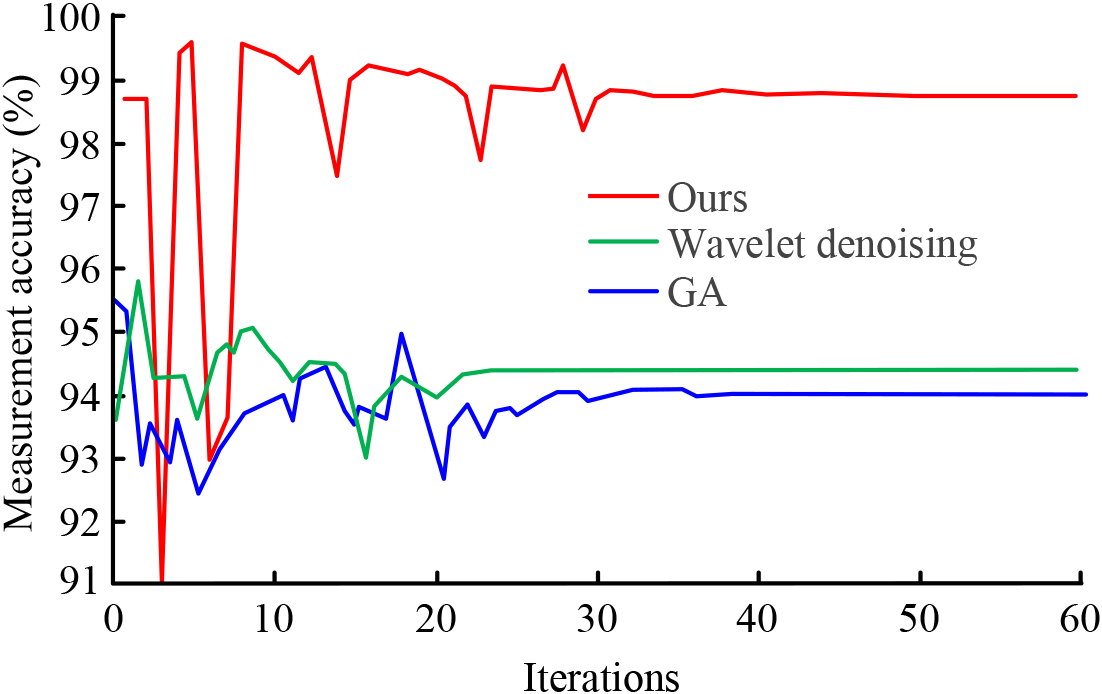
CNC error measurement effect evaluation
The study constructed a MACNC error model in which the error measurement and identification of the CNC were carried out. Therefore, the effectiveness of the measurement and identification method proposed by the study was first evaluated in the experimental test. Taking XKA714
Thereafter, the variation of the measurement error values of the algorithms for different types of parts machined during the machine operation was analyzed as a way. This is to further determine the accuracy of the measurement method, in Fig. 5. In Fig. 5, the study evaluates the variation of the measurement error during the machining of polygonal and circular workpieces. Figure 5(a) shows the measurement error during the machining of the polygonal workpiece. The error in the measurement of the proposed measurement method gradually decreases and eventually decreases to 0.001, while the error of the remaining two algorithms can show a trend of continuous decrease, but the final measurement error still reaches 0.007. Figure 5(b) shows the measurement error during the machining of the circular workpiece. The experiment reveals that the measurement method proposed in the study exhibits a significantly lower error than the remaining two algorithms and its error is reduced to less than 0.001. These results show that the measurement method proposed in the study is effective and has a high accuracy.
Evaluation of algorithm measurement error value.
Next, the differences in the error recognition accuracy of each method in error measurement are analyzed in Fig. 6. In Fig. 6, the variation of the recognition accuracy of the studied error measurement method for geometric motion errors and control errors is analyzed and compared with the traditional method. The identification of geometric motion errors, the final identification accuracy of the proposed measurement method finally reaches 98.2%. It is significantly higher than that of the traditional method. For control errors, the accuracy of the proposed measurement method is stabilized above 98% after 4 s fluctuation. From Fig. 5, it can be seen that the geometric motion error trend of the proposed measurement method is almost consistent with that of traditional measurement methods. From Fig. 5(a), it can be seen that both measurement methods experienced up and down oscillations within 0S-4S in the early stage of measurement. During the oscillation process, the lowest and highest recognition accuracy obtained by the proposed measurement method were 96.0% and 99.4%, respectively, compared with the minimum and maximum recognition accuracy of 96.2% and 99.1% of traditional measurement methods, the minimum accuracy is reduced by 0.02% and the maximum accuracy is increased by 0.03%. From Fig. 5(b), it can be seen that both measurement methods experienced irregular oscillations within 1S-5S. The proposed measurement method achieved a minimum recognition accuracy of 97.0% and a maximum recognition accuracy of 99.5%, respectively. Compared with the traditional measurement methods’ minimum recognition accuracy and maximum recognition accuracy of 96.7% and 99.2%, both improved by 0.03%, respectively. In summary, it can be seen that the measurement method proposed in the study has better measurement performance compared to traditional measurement methods.
Finally, based on the error measurement method of CNC proposed in the study, the motion error variation of CNC during machining was analyzed by simulation experiments, in Table 1. 10 measurement points were set in the study, and the measured differences between the measured and actual values were analyzed. Table 1 shows that the error measurement method proposed in the study can effectively identify the motion errors in the machining and derive the percentage of errors in the current machining. And the measurement results indicate that the error of the multi-axis CNC machine under the simulation conditions is more obvious, for which error compensation is needed.
Motion error measurement results
Motion error recognition accuracy.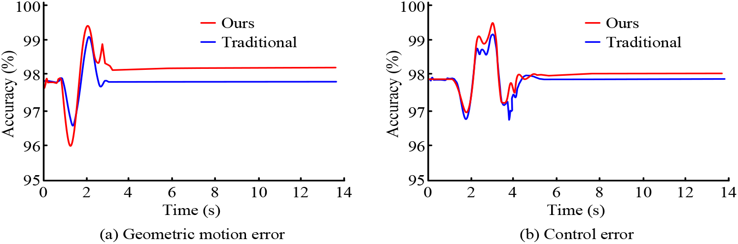
Based on the results of the simulation experiments, the motion error compensation method proposed in the study is used to eliminate the errors. To verify the effectiveness of the motion error compensation method, the study designs a comparison experiment to evaluate the algorithm performance, in Fig. 7. In Fig. 7, the change of the loss value between the algorithm proposed in the study and the error compensation algorithms based on BP algorithm, PSO algorithm, and GA is compared. It can be found from the curve changes that the loss value of the compensation algorithm proposed by the study decreases to 0.01 and finally stabilizes at 0.005 after 50 iterations of calculation. The loss values of the remaining algorithms show a trend of continuous decrease, and the loss value of the compensation algorithm based on the PSO algorithm finally stabilizes at 0.01, which is significantly higher than that of the compensation algorithm proposed by the study. The proposed compensation algorithm has a lower loss value and its convergence speed is faster.
MECA loss value change.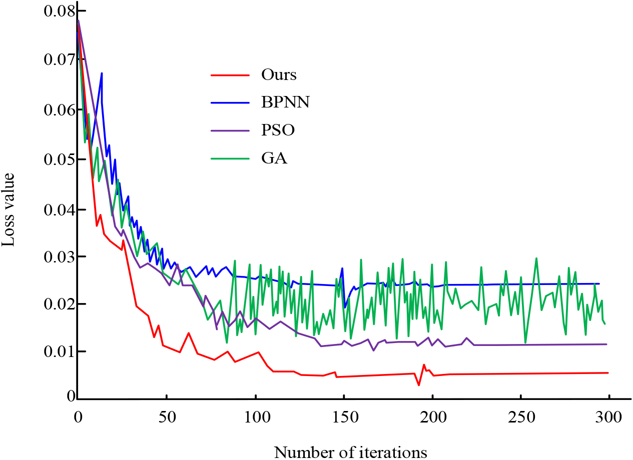
In order to analyze the anti-interference ability of multiple algorithms, a mathematical model was written in Matlab using the principle of numerical analysis. A multi axis linkage machine tool motion error model was built based on the Simulink environment, and noise information was added to interfere during the simulation experiment. The results obtained are shown in Fig. 8. In Fig. 8, the study adds interference during the simulation experiment to evaluate the ability of each algorithm to handle the interference. It illustrates that the error compensation accuracy of all algorithms decreases when the disturbance information is added at the test time of 10 s, among which the motion error compensation algorithm (MECA) proposed by the study is able to return to the steady state more quickly. In addition, the accuracy of the proposed error compensation algorithm is significantly higher than that of the remaining three methods, and its stability value reaches 99.2%. The accuracy stability of three error compensation methods based on BP neural network, particle swarm optimization algorithm and genetic algorithm reached 98.8%, 97.6% and 97.2% respectively. The error compensation algorithm proposed in the study has improved by 0.4%, 1.6%, and 2% compared to these three methods, respectively. When disturbed, the accuracy rate of the error compensation algorithm proposed by the research is 93.9%, which is 2%, 2% and 3.5% higher than the minimum values of 91.9%, 91.9% and 90.4% of the three error compensation algorithms based on BP neural network, Particle swarm optimization algorithm and genetic algorithm, respectively The proposed error compensation algorithm has strong anti-interference ability and high compensation accuracy.
Evaluation of anti-interference ability of motion error compensation algorithm.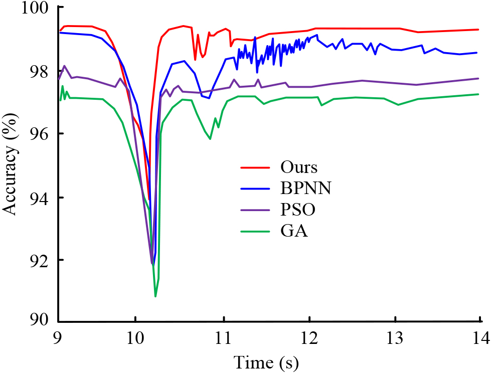
The results of the multi-algorithm comparison show that the compensation algorithm proposed in the study is effective. Consequently, to verify its effectiveness in error compensation, the time consumption in error compensation is compared with that of the conventional compensation algorithm, in Fig. 9. Figure 9 shows that the processing time of the compensation algorithm proposed in the study is significantly lower than that of the conventional error compensation algorithm, and the lowest processing time is only 0.012 s.
Comparison of processing time of MECAs.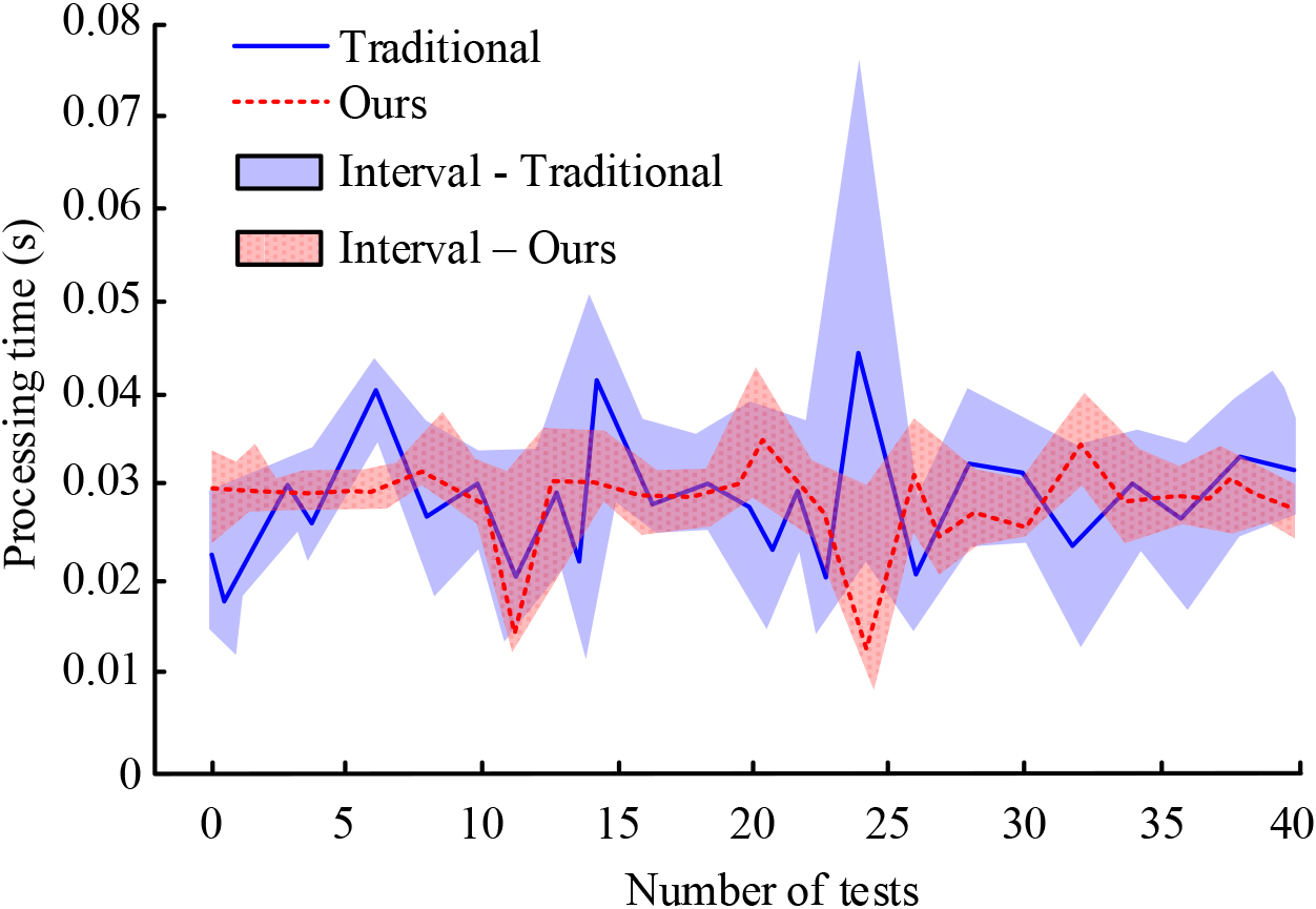
Finally, the error compensation algorithm proposed by the study is used to conduct the MACNC motion error compensation experiments. The simulation experiments are set up to obtain the machine tool compensation results in Fig. 10. The difference in position coordinates before and after the error compensation is analyzed in Fig. 10, after the error compensation, the position coordinates of the CNC gradually converge to the ideal value during the machining of the workpiece. Therefore, the above results reveal that the MECA proposed by the research can effectively reduce the workpiece machining motion error and improve the machining accuracy of the MACNC.
In order to observe the effectiveness of the proposed multi axis linkage CNC machine tool motion error compensation algorithm more clearly, the performance of this algorithm was compared and analyzed with error compensation algorithms based on fast non dominated sorting genetic algorithm (NSGA-II), adaptive variable step interpolation (AVSI), and adaptive bow height error control interpolation (ABHECI). NSGA-II is one of the most popular multi-objective Evolutionary algorithm, which is improved on the basis of genetic algorithm. The ABHECI algorithm can effectively avoid the problems of error overruns and conservative step sizes that traditional equal arch height error methods often encounter. The algorithm calculates a small number of interpolation points and has the advantage of high machining efficiency. The AVSI algorithm is an effective interpolation method, which is essentially a multivariate function fitting technique that can dynamically fit and modify paths based on the characteristics of motion trajectories to achieve the fitting effect of the shortest path and minimum curvature. The measurement performance of the four motion error compensation algorithms is shown in Table 2. From Table 2, it can be seen that the measurement performance of the proposed multi axis linkage CNC machine tool motion error compensation algorithm is significantly superior to the other three algorithms. Among them, the measurement accuracy of the proposed algorithm is improved by 23.31%, 13.81%, and 8.81% compared to the NSGA-II algorithm, AVSI algorithm, and ABHECI algorithm, respectively; Compared with the other three algorithms, the accuracy under interference has increased by 34.83%, 22.36%, and 20.54%, respectively; Compared with the other three algorithms, the measurement error has decreased by 0.893, 0.548, and 0.346, respectively; Compared with the other three algorithms, the running time has decreased by 3.635 seconds, 15.455 seconds, and 0.959 seconds, respectively. In summary, it can be seen that the motion error compensation algorithm proposed in the study for multi axis linkage CNC machine tools has good measurement performance.
Measurement performance of four motion error compensation algorithms
Motion error compensation effect.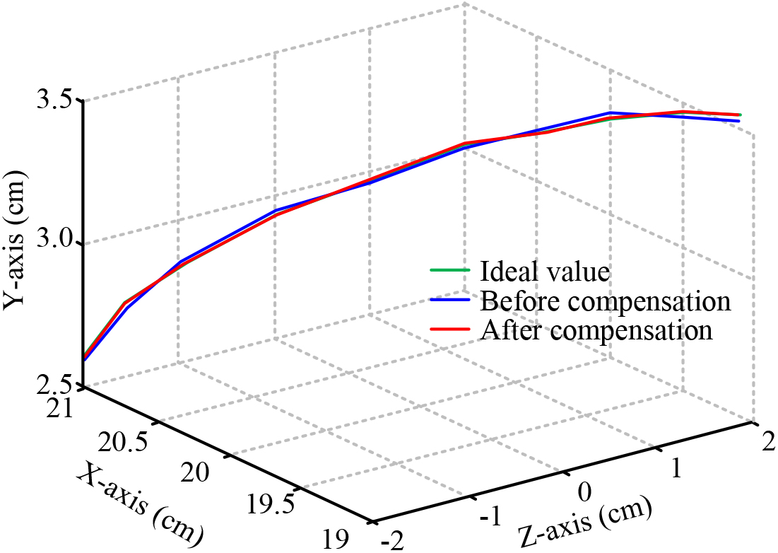
As a new way of machining workpieces, the compensation of the motion errors during machining will improve the efficiency of machining as well as the accuracy of the parts. To this end, the study proposes an error measurement method for the motion errors in multi-axis CNC machines. And according to this, an error compensation algorithm based on cubic spline fitting is proposed, and simulation experiments are set up to verify the effectiveness of the compensation algorithm. The simulation results reveal that the measurement accuracy of the error measurement method proposed in the study reaches 98.95%, Compared with the minimum measurement accuracy based on wavelet denoising and genetic algorithm, it has improved by 4.49% and 4.88%, respectively. When the number of iterations is 5, all three measurement methods achieve the minimum measurement accuracy. The minimum measurement accuracy of the proposed measurement method is 91.00%, which is 2.65% and 3.26% lower than the minimum measurement accuracy based on wavelet denoising and genetic algorithm of 93.65% and 94.26%, respectively. When disturbed, the accuracy rate of the error compensation algorithm proposed by the research is 93.9%, which is 2%, 2% and 3.5% higher than the minimum values of 91.9%, 91.9% and 90.4% of the three error compensation algorithms based on BP neural network, Particle swarm optimization algorithm and genetic algorithm, respectively. and at the same time, its accuracy of error identification is maintained above 98%. The simulation test of the compensation algorithm demonstrates that the error compensation algorithm has high stability for the motion error of MACNC, can effectively avoid external interference, and can control the compensation accuracy at 99.2%. Finally, through simulation application test, it is found that the processing time of the error compensation algorithm proposed in the error compensation is small, the minimum processing time is only 0.012 s. The compensation algorithm can effectively reduce the machining error and improve the machining accuracy of CNC. The above results show that the error compensation algorithm proposed in the study can effectively avoid the motion errors of the MACNC, and then improve the machine tool machining efficiency and quality. However, there are many factors affecting the accuracy of MACNC, and only the motion errors are analyzed in the study, so the rest of the errors in the machine tools will be investigated in depth in the subsequent study to improve the machine performance. Due to limitations in time and conditions, this article only conducts simulation experiments on the error model of the multi axis linkage CNC machine tool constructed. Error analysis is conducted by adjusting the parameters on the simulation platform, without testing on actual machine tools. Therefore, the experimental results are not comprehensive enough, and further improvement is needed in this regard.