
Abstract
During five-axis CNC machining, the dynamic tracking error of the five-axis machine tool caused by imperfect servo dynamic performance is the major factor affecting the accuracy during high-speed and high-precision manufacturing. Rotation tool center point (RTCP) test has become a typical kinematic test for the dynamic tracking error of five-axis machine tools. According to the mechanism and characteristics of dynamic tracking error, during the RTCP test, relating the measured dynamic tracking error to corresponding occurring situation is helpful for the research of calibration or reduction of dynamic tracking error. In this paper, a new method to relate dynamic tracking error to occurring situation based on additional rectilinear motion is attempted. During this method, rectilinear motions are added into the RTCP test process, and the dynamic tracking error and corresponding occurring position can be calculated from the scale of rectilinear motion. By six tests with rectilinear motions in and against X, Y and Z directions, the additional error and uncertainty of the test process can be offset by calculation. This method can be implemented without any addition or modification to the instrument or NC system.
Introduction
Five-axis CNC machine tools are at the core and forefront of the high-end manufacturing industry due to high efficiency and precision. For a five-axis machine tool, machining error sources can be classified into geometric, thermal, cutting force and servo system tracking errors. Existing researches have shown that the dynamic tracking error caused by imperfect servo dynamic performance is the major factor affecting the accuracy during high-speed and high-precision manufacturing.1,2
There are two different methods to detect the dynamic tracking error of five-axis machine tools: evaluation by test piece and kinematic test by instrument. Evaluation by test piece is evaluating the dynamic tracking error by machining standard test pieces such as NAS979 3 and S-shaped test pieces,4–6 as well as inspecting its contour accuracy and quality. However, the contour accuracy of the test piece is caused by the coupling processes of different factors. Hence, this method is only suitable as a total evaluation of dynamic performance but not as a dedicated dynamic tracking error measurement or test.
Kinematic test with instrument is a direct method of detecting dynamic tracking error. Circle test and rotation tool center point (RTCP) test are the two most typical kinematic tests. The double ball bar (DBB) is always used while performing the circle test. Bryan7,8 first developed the DBB method to inspect the contouring behavior of CNC machines. In recent years, a few researchers have been focusing on the dynamic tracking error test based on DBB. Lei et al. 9 summarized the DBB testing error patterns of servo gain mismatch, backlash and tracking direction as a diagnosis of the error sources. Le Flohic et al. 10 proposed a model-based servo tuning method based on DBB to reduce dynamic tracking error.
The RTCP test is another popular kinematic test, which is based on the rotation tool center point (RTCP) function. In the RTCP test, the tool tip (tool center point, TCP) is set to remain still, while the rotary axes are set to run. The deviation of the tool tip from the set point can be considered as the dynamic tracking error of the machine tool. Compared with other measurements, the RTCP test has the advantages of high accuracy, variable detection trajectory and less interference. In 2004, Weikert invented an instrument termed R-test for the RTCP test, which consisted of three orthogonal displacement sensors and a ball set on a spindle. In recent years, improved instruments for the RTCP test have been invented, such as capball, 2 non-ball, 11 and non-contact R-test. 12 Researchers have made attempts for dynamic tracking error measurement based on the RTCP test. Bringmann et al.13,14 designed a three-axis circular trajectory for the RTCP test to separate the motion errors of the translational and rotary axes. Zhong et al. 15 designed a new S trajectory according to the standard S-shaped test piece to evaluate the dynamic performance. Jiang et al.16–18 designed an eight-shape RTCP trajectory and proposed a dynamic tracking error tracing method based on feature extraction.
The dynamic tracking error is not inherent in machine tool, but caused by the tracking error of each motion axis control process, which is different from geometric error, thermal error and cutting force error. Thus, for the research of calibration or reduction of dynamic tracking error, during the RTCP test process, the testing result is affected by the corresponding position and motion state of each motion axis. However, the above-mentioned instruments and measurements for the RTCP test is inconvenient to figure out and rebuild this relationship. In recent years, researchers have tried to relate error to corresponding occurring situation. Ibaraki et al. 19 attempted to associate the swing angle and rotary angle collected in the NC system to tool tip deviation measured by the R-test; Ding et al. 20 invented a tool tip position error and tool posture synchronous detection mechanism, which consisted of three orthogonal displacement sensors and two rotary encoders. The above methods can be applied to relate the error to its occurring situation, but the measuring processes must include the changes of device structure or NC system, which are difficult to apply and not suitable for widespread use.
In this paper, a new method to relate dynamic tracking error to occurring situation based on additional rectilinear motion is attempted. During this method, rectilinear motions are added into the RTCP test process, and the dynamic tracking error and corresponding occurring position can be calculated from the scale of rectilinear motion. By six tests with rectilinear motions in and against X, Y and Z directions, the additional error and uncertainty of the test process can be offset by calculation. This method can be implemented without any addition or modification to the instrument or NC system.
The paper is organized as follows: in Section 2, the mechanism and characteristics of dynamic tracking error are summarized, and the necessity and value of relating dynamic tracking error to occurring situation is analyzed; the detection and calculation method for dynamic tracking error and its corresponding occurring situation are shown in Section 3; the effectiveness of this relating method is verified through experiments in Section 4; finally, the conclusion of this paper is in Section 5.
Dynamic tracking error and its occurring situation in RTCP test
Mechanism and characteristics of dynamic tracking error of five-axis machine tools
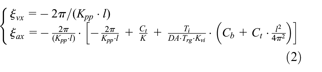
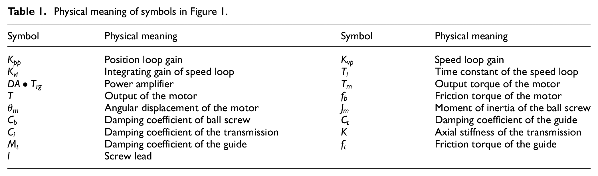
In five-axis machine tools, the servo control systems of the linear axis and rotary axis are established as displayed in Figures 1 and 2 respectively. Herein, the physical meanings of symbols are shown in Tables 1 and 2. For linear motion axes, the relationship between actual axis position


Servo system configuration of each linear axis.

Servo system configuration of each rotary axis.
Physical meaning of symbols in Figure 1.
Physical meaning of symbols in Figure 2.

Similarly, for rotary motion axes, the relationship between actual axis position


The deviation between actual and ideal output can be defined as tracking error, as shown in equations (5) and (6):


where
The tracking error of each motion axis will cause tool tip deviation of the machine. Herein, a five-axis machine tool with a tilting rotary table (B-type) is considered as an example, as shown in Figure 3 (the same in the below of this paper). The kinematic chain of the machine tool can be described by multi-body system theory, as shown in Figure 4, and the kinematic transform can be formulated as equations (7) and (8):


where

Thus, the relationship between motion axes tracking errors

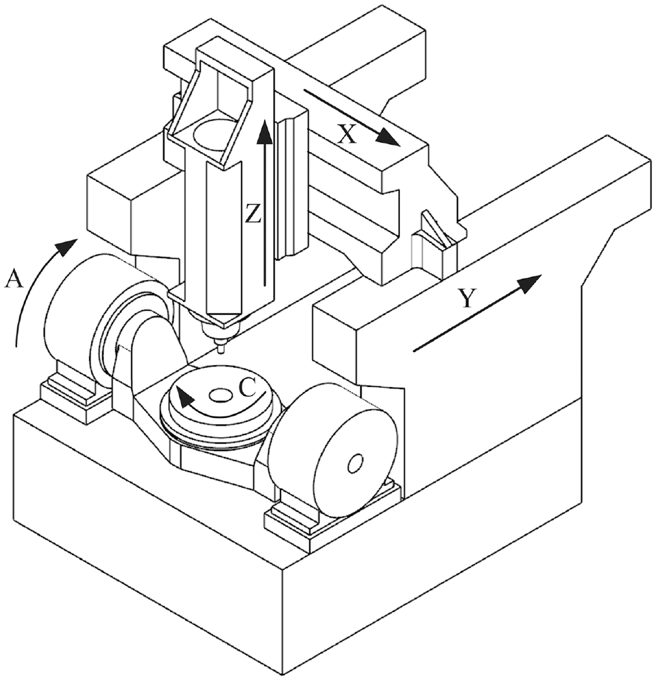
Five-axis machine tool with a tilting rotary table.

Topological structure and coordinates transform of the machine tool in Figure 3.
To summarized, the dynamic tracking error of five-axis machine tool can be considered as the nonorthogonal coupling result of the tracking errors of all the five motion axes.
Value of relating dynamic tracking error to its occurring situation in RTCP test
The RTCP test is a commonly used dynamic tracking error evaluation method, which is based on the RTCP function of five-axis machine tools. Figure 5 shows a typical mechanical structure of RTCP test device, which consisted of three orthogonal displacement sensors and a ball set on a spindle. In the RTCP test, the tool tip (or tool center point) is set to remain still, while the rotary axes are set to run, as shown in Figure 6, and the deviation of the tool tip from the set point can be collected as the dynamic tracking error of the machine tool. Compared with other test or measurement, during the RTCP test, the tool tip is set to move in a smaller range, which requires smaller range but offers higher accuracy. With the above advantage, the RTCP test is widely used in the accuracy evaluation and measurement of five-axis machine tools, and included in the ISO standard. 21

Basic mechanical structure of rotation tool center point (RTCP) test device.

Rotation tool center point (RTCP) test.
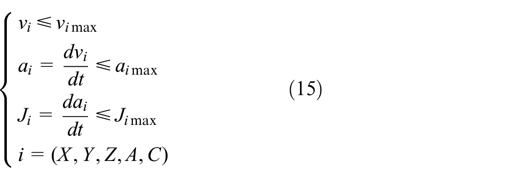
In recent years, for the test or evaluation of dynamic performance under complicated motion states, the RTCP test trajectory evolve from arc (such as ISO-AK4 trajectory) or circle to complicated trajectories,18,22 as shown in Figure 7. The RTCP test in general can only show the shape and value of the tool tip deviation, which is suitable for the simple arc or circle test trajectory. However, for the complicated RTCP trajectories, the test processes may include complicated velocity or acceleration changes, so the shape and value of tool tip deviation cannot include enough information of the dynamic tracking error. As the analysis in Section 2.1, the dynamic tracking error is affected by tracking error of each motion axis, and further affected by the position, velocity and acceleration of each motion axis. Thus, there is a mapping relationship between the dynamic tracking error and the corresponding occurring situation (positions, velocities and accelerations of all the five motion axes), as equation (11) shows:


Developing trend of rotation tool center point (RTCP) test trajectories.
Herein, it should be noted especially that, the “mapping relationship” mentioned above does not follow the strict mathematical definition, but means that every dynamic tracking error situation can be related to its corresponding motion axis positions, velocities and accelerations while the error occurred. For the research of dynamic tracking error, the mapping relationship between the dynamic tracking error and the corresponding occurring situation is very important, especially for the complicated RTCP test trajectories which include complicated velocity or acceleration changes, but the traditional RTCP test cannot directly rebuild this relationship in the testing process.
Theoretically, time corresponding motion axis positions, velocities and accelerations can be calculated from the feedrate and rotary axis position commands of NC code, as shown in equations (12) and (13):
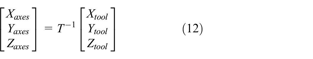

Herein, T is kinematic transform matrix from each motion axis to tool tip, and the tool tip setting position

where t is the corresponding moment of dynamic tracking error test result
where
Currently, two ways were proposed to overcome the above shortage. Some researchers chose to measure the tool tip deviation by RTCP device, collect the corresponding axis positions, velocities and accelerations, and then build the relationship by time alignment matching, 19 as equation (16) shows:

where

The above methods can be applied to relate the error to its occurring situation, but the measuring processes must include to the changes of device mechanical structure or NC system, which are difficult to apply and not suitable for widespread use. Thus, in next section, a new method to relate dynamic tracking error to occurring situation based on additional rectilinear motion is attempted.
A new relating method between error and occurring situation based on additional rectilinear motions
Scheme of the new relating method
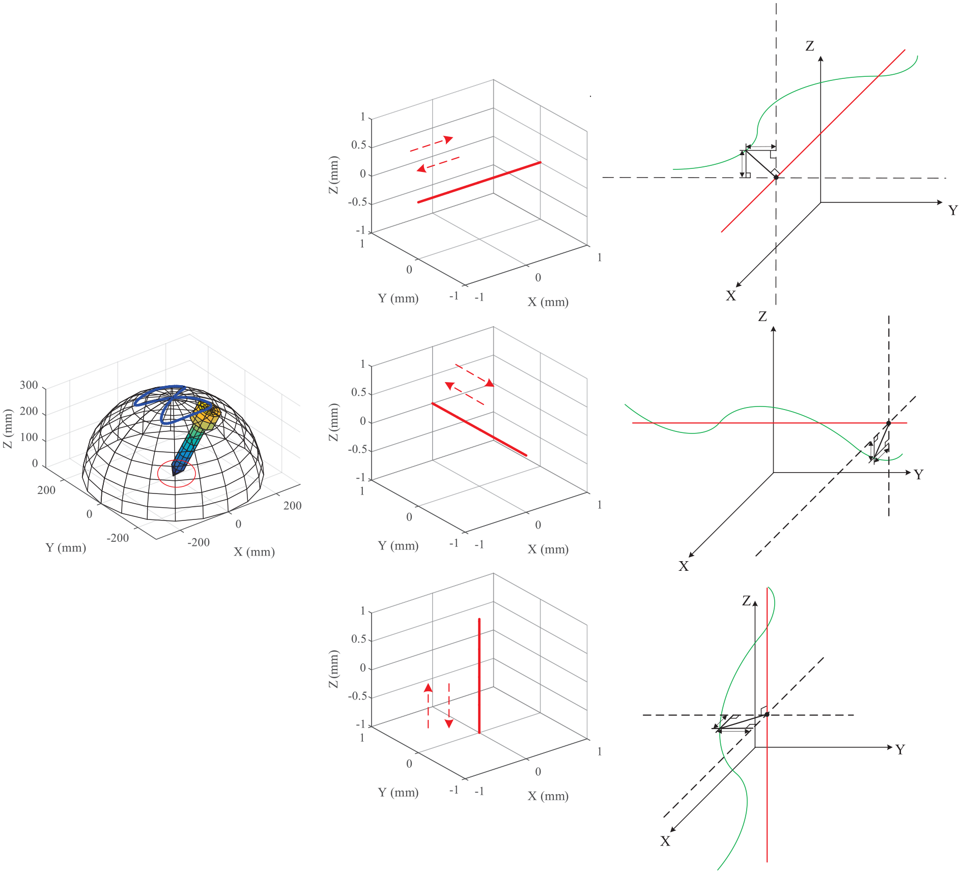
In the general RTCP test, the tool tip should be set to remain still, while the rotary axes are scheduled to move. In this section, in order to relate tool tip deviation to corresponding occurring situation, the tool tip is set to do uniform motion rectilinearly while the rotary axes are running, as shown in Figure 8. Due to the simultaneous motion of rotary axes and tool tip, each position in the scale of rectilinear motion corresponds to a occurring situation combo, so the dynamic tracking error in the orthogonal direction of the rectilinear motion can be corresponded to the occurring situation as shown in Figure 9. In order to test the dynamic tracking error in the X, Y and Z direction in the whole test process, the RTCP tests with rectilinear motions in X, Y and Z directions should be conducted separately.

Tool tip rectilinear motion in rotation tool center point (RTCP) test.

Principle of the new relating method.
Additional rectilinear motions in and against the direction
In the RTCP test, the tool tip is set to remain still. Therefore, the RTCP test process can be expressed according to equation (18):

where [X0, Y0, Z0] is the position where the tool tip is set, and [f(t), g(t)] is the description of the motions of rotary axes during the RTCP test, which can be seen as functions of time series t. For the new relating method, the tool tip is set to move 2 mm in and against the direction while the rotary axes perform their motion during the process of RTCP test. Here, the tests with 2 mm in X+ and X– directions are considered as an example. Due to the 2 mm of additional rectilinear motions in X+ and X– direction, the RTCP test process can be expressed in terms of equation (19):

where

where [ex, ey, ez] is the dynamic tracking error, which can be seen as functions of t; and

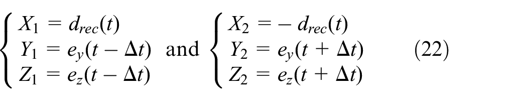
where (X1,Y1,Z1) and (X2,Y2,Z2) are the tool tip positions of the tests with rectilinear motions in and against X direction. By the equivalent substitution of time series, the tool tip positions with X+ and X– motions can be demonstrated according to equation (22):
Herein, according to NC command, every

so equation (23) can be transformed into equation (24) as:

herein, in comparison to T,


Additional rectilinear motions and corresponding calculation method.
If the dynamic tracking error in X+ and X– directions
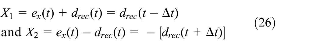
Thus, the almost same calculation can be taken and equation (29) can be true whether
Six tests with rectilinear motions in and against the X, Y, and Z direction
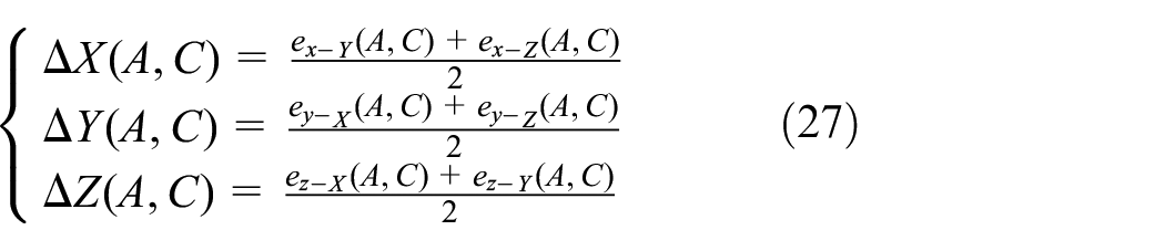
According to the above calculation, the dynamic tracking errors in Y and Z directions [ey-X, ez-X] can be calculated and corresponded to the ideal posture angle couple to the scale of rectilinear motion in X+ and X- directions. In a similar manner, the dynamic tracking errors in X and Z directions [ex-Y, ez-Y] can be calculated and corresponded from the scale of rectilinear motion in Y+ and Y– directions. The dynamic tracking errors in X- and Y-directions [ex-Z, ey-Z] can be calculated and corresponded to the scale of rectilinear motion in Z+ and Z– directions. It should be noted that, the error caused by the lack of sensor resolution, uncertainty and the inherent error of RTCP device may be enlarged during the test with additional rectilinear motions. By six tests in different directions, as shown in Figure 11, the dynamic tracking errors in X, Y and Z directions can be measured twice, so to reduce the impact of instrument error and the uncertainty of measurement, the dynamic tracking error in each direction should be calculated as the mean value of two measurement, as shown in equation (27).
Tool tip rectilinear motion in X+, X–, Y+, Y–, Z+ and Z– directions.
According to equations 12 and 13 in Section 2.2, the occurring situation, including position, velocity and acceleration of each motion axis, can be calculated from (A, C) and time series t. It should be specially explained that, in the calculation of occurring situation, (A, C) means actual tool posture angles, and in this section, (A, C) means corresponding ideal tool posture angles, but the deviation between those two can be treated as the residual of the calculation and ignored.
To summarized, according to the above calculation, the mapping relationship between dynamic tracking error and corresponding occurring situation can be established according to tool tip position

Experiment
Experimental setup
To validate the proposed “error to corresponding occurring situation” relating method, an experiment was conducted on a five-axis machine with a tilting rotary table, whose configurations are shown in Figure 3. The NC system utilized is SIEMENS 840D SL. An RTCP device, as shown in Figure 12, was also used in this experiment. The machine tool was set to move on an 8-shape RTCP trajectory, 26 as shown in Figure 13. The experiment was conducted as follows: first, the RTCP test with additional rectilinear motions was performed, and the dynamic tracking errors and corresponding occurring situation are acquired; second, as a contrast, the ordinary RTCP test (without additional rectilinear motions) with the same trajectory and experimental setting was performed, and the dynamic tracking errors were also acquired; finally, the tracking errors acquired by the two tests above were compared to verify that the “error to corresponding occurring situation” relating method can be implemented without additional deviation.

Rotation tool center point (RTCP) test instrument.

Eight-shape trajectory.
It should be noted especially that, for the RTCP test with additional rectilinear motions, the feedrate setting should be adjustment in order to keep the rotary axis motions consistent. In the NC system of five-axis CNC machine tool, the feed rate F has two different definitions in motion models while the RTCP function is on: 27
(1) If only the rotary axes are set to move, F is defined as the resultant angular velocity of the two rotary angles, as calculated according to equation (29):
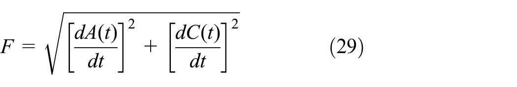
Here, the feed rate has the dimension of angular velocity (usually in deg/min).
(2)If the rotary axes and linear axes are set to move simultaneously, F is defined as the resultant velocity of tool tip, as calculated according to equation (30):

where [X, Y, Z] is the tool tip position. Here, the feed rate has the dimension of velocity (usually in mm/min).
Thus, in order to keep the velocities of rotary axes the same after the addition of the rectilinear motion, the feed rate should be converted by equation (31):

where
Experimental results and analysis
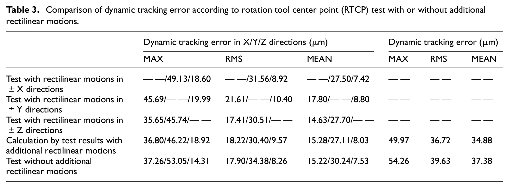
The RTCP test with additional rectilinear motions was performed as shown in Figure 14, and the separate test results of tests with different rectilinear motions are shown in Figure 15 and Table 3. To avoid the tracking error covered due to shock of start, the measurement part of the result in normal machine tool working condition was considered. According to the calculation mentioned in Section 3.3, the dynamic tracking errors and corresponding tool posture combo can be acquired, as shown in Figure 16. Then all the corresponding each axis position, velocity and acceleration can be calculated by equations (12) and (13) in Section 2.2, as shown in Figure 17. In order to verify that the RTCP test with additional rectilinear motions and corresponding calculation and relating method would not cause additional deviation, the ordinary RTCP test (without additional rectilinear motions) with the same experimental setting was performed, and the comparison of dynamic tracking errors acquired by above two tests is shown in Figure 18 and Table 3.

Rotation tool center point (RTCP) tests with additional rectilinear motions: (a) rectilinear motion in X+, (b) rectilinear motion in X–, (c) rectilinear motion in Y+, (d) rectilinear motion in Y–, (e) rectilinear motion in Z+, and (f) rectilinear motion in Z–.

Results of rotation tool center point (RTCP) test with additional rectilinear motions: (a) rectilinear motion in X+, (b) rectilinear motion in X–, (c) dynamic error calculated by test with ±X motions, (d) rectilinear motion in Y+, (e) rectilinear motion in Y–, (f) dynamic error calculated by test with ±Y motions, (g) rectilinear motion in Z+, (h) rectilinear motion in Z–,and (i) dynamic error calculated by test with ±Z motions.
Comparison of dynamic tracking error according to rotation tool center point (RTCP) test with or without additional rectilinear motions.
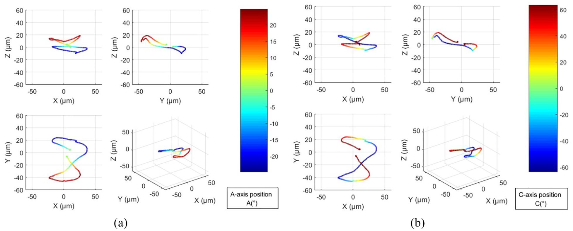
Dynamic tracking error and corresponding tool postures according to rotation tool center point (RTCP) test with additional rectilinear motions: (a) dynamic tracking error and corresponding A-axis position, and (b) dynamic tracking error and corresponding C-axis position.

Dynamic tracking error and corresponding axis positions, velocities and accelerations according to rotation tool center point (RTCP) test with additional rectilinear motions: (a) dynamic tracking error and corresponding X-axis position, (b) dynamic tracking error and corresponding Y-axis position, (c) dynamic tracking error and corresponding Z-axis position, (d) dynamic tracking error and corresponding X-axis velocity, (e) dynamic tracking error and corresponding Y-axis velocity, (f) dynamic tracking error and corresponding Z-axis velocity, (g) dynamic tracking error and corresponding A-axis velocity, (h) dynamic tracking error and corresponding C-axis velocity, (i) dynamic tracking error and corresponding X-axis acceleration, (j) dynamic tracking error and corresponding Y-axis acceleration, (k) dynamic tracking error and corresponding Z-axis acceleration, (l) dynamic tracking error and corresponding A-axis acceleration, and (m) dynamic tracking error and corresponding C-axis acceleration.

Comparison of dynamic tracking error according to rotation tool center point (RTCP) test with or without additional rectilinear motions: (a) test with additional rectilinear motions and (b) test without additional rectilinear motions.
According to above experiments and comparison, the following observations were made:
According to the RTCP test with additional rectilinear motions and corresponding calculation method, the corresponding each axis position, velocity and acceleration can be calculated.
For RTCP test with or without additional rectilinear motions, the variation tendencies and shape characteristics of the measured dynamic tracking errors displayed a good match with respect to the two measurements.
The core indexes, including maximum, mean and root mean square (RMS), of those two test results were very close, which were lower than 5 μm. It should be noted that, for the sensors applied in this experiment, the uncertainty of each sensor is 2 μm, which means the deviation of those two test results can be treated as the error mainly caused by sensor uncertainty.
According to Table 3, in comparison with the dynamic tracking errors directly gotten from the test with single-direction rectilinear motion, the dynamic tracking error calculated by results of 6 tests was often closer to the dynamic tracking error without rectilinear motion, which means the 6 tests with rectilinear motions is helpful to offset the additional error and uncertainty of the test process.
To sum up, the RTCP test with additional rectilinear motions can be used to relate dynamic tracking error to its corresponding occurring situation, and there is no additional deviation introduced during this test process.
Conclusion
The RTCP test is a popular kinematic test for the dynamic tracking error of five-axis machine tools. According to the mechanism and characteristics of dynamic tracking, during the RTCP test, relating the measured dynamic tracking error to corresponding occurring situation is helpful for the research of calibration or reduction of dynamic tracking error. However, the existing RTCP devices or testing methods cannot implement this function perfectly and conveniently.
In this paper, a new method to relate dynamic tracking error to occurring situation based on additional rectilinear motion is attempted. During this method, rectilinear motions are added into the RTCP test process, and the tracking error and corresponding occurring position can be calculated from the scale of rectilinear motion. To validate the proposed relating method, an experiment was conducted on a five-axis machine with a tilting rotary table. It can be observed according to the experimental results that the new relating method can be used to relate dynamic tracking error to its corresponding occurring situation, and there is no additional deviation introduced during this process. This method can implement the “error-occurring situation” relating function without any addition or modification to the instrument and NC system.
Footnotes
Handling Editor: James Baldwin
Authors’ contributions
Formal analysis, Jing Zhang and Li Du; Investigation, Qicheng Ding and Jiexiong Ding; Writing – original draft, Qicheng Ding; Writing – review & editing, Jiexiong Ding.
Declaration of conflicting interests
The author(s) declared no potential conflicts of interest with respect to the research, authorship, and/or publication of this article.
Funding
The author(s) disclosed receipt of the following financial support for the research, authorship, and/or publication of this article: The (04) National Science and Technology Major Projects of China (Grant No. 2017ZX04002001-002).