
Abstract
This article proposes a stability-enhanced alternative to traditional buckling-restrained steel braced frames (BRBFs) for application in tall-rise steel buildings located in high seismic regions. The viscoelastic (VE)-BRBF is a BRBF featuring V or inverted-V bracing configurations and integrates vertically aligned VE dampers at beam–brace intersections on each story. The incorporation of VE dampers addresses two significant drawbacks of traditional BRBFs. First, it enhances the post-elastic lateral story shear stiffness, crucial for mitigating P-delta-induced inelastic drift concentrations and global instability, particularly under subduction interface events. Second, it augments inherent damping, a parameter typically low in conventional steel buildings. These improvements alleviate the need for the stability-related stringent height limitations imposed by design codes, such as the 40 m limit for SC4 buildings in Canada. Utilizing nonlinear response history analysis, the seismic stability performance of the proposed system is assessed against traditional BRBFs designed with classical strength amplification through an inelastic stability coefficient. The assessment is conducted on 10- and 20-story steel buildings in Vancouver, BC, considering seismic excitations involving the subduction interface. The results demonstrate that traditional BRBF designed overlooking height limitations failed to meet design code acceptance criteria, with several stability cases exhibiting global instability and excessive drifting. In contrast, the incorporation of VE dampers in the VE-BRBF demonstrated responses that met the design code acceptance criteria, with uniform drift distributions and mitigated P-delta effects and with residual post-earthquake drifts within repair limits, regardless of building height or seismic excitation type.
Introduction
Steel buckling-restrained braced frames (BRBFs) exhibit stable energy dissipation and buckling-free response with the capability of developing isotropic and kinematic strain hardening under cyclic loading (Black et al., 2004; Fahnestock et al., 2003, 2007; Iwata and Murai, 2006; Tremblay et al., 2006; Uang et al., 2004; Zhao et al., 2011). Despite these favorable characteristics, international design codes prohibit the utilization of BRBFs as seismic force resisting systems (SFRSs) in tall buildings in high seismic regions. For example, according to the National Building Code of Canada (NBC 2020), BRBFs are limited to buildings with a height lower than 40 m in Seismic Categories SC3 and SC4. Similarly, American Society of Civil Engineers (ASCE) 7-22 buildings in Seismic Categories D and E are restricted to 160 ft and those in Seismic Category F are limited to 100 ft. In Japan, BRBFs are used only as part of a dual system with moment frames acting as the primary SFRSs (Huang et al., 2000; Iwata et al., 2018), or for retrofitting purposes (Gutiérrez-Urzúa and Freddi, 2022). These constraints and coupling requirements, dictated by design codes, primarily address stability concerns since BRBFs exhibit modest kinematic strain hardening at large deformations, resulting in insufficient post-elastic lateral story shear stiffness to counteract the negative stiffness induced by P-delta effects in tall buildings (Erochko et al., 2011; Hariri and Tremblay, 2021; Sabelli, 2001; Zaruma and Fahnestock, 2018). Consequently, BRBFs are susceptible to dynamic instability during intense seismic events, such as subduction interface earthquakes, characterized by significant drifting and the development of negative story stiffness—a precursor to dynamic instability as defined in the structural commentary of the ASCE 7.
To mitigate P-delta effects in steel SFRSs, past studies (Akiyama, 2002; Gupta and Krawinkler, 2000; Hariri et al., 2024a; Tremblay, 2018) proposed incorporating secondary lateral story shear stiffness by adding elastic members that are not designed to dissipate seismic energy. The role of these added elements is to enhance the story post-elastic shear stiffness of primary SFRSs to counter the negative stiffness of P-delta effects. Hariri (Hariri, 2023; Hariri et al., 2024a, 2024b) quantified the required secondary stiffness for canceling out the P-delta effects and ensuring resilient post-earthquake residual drifts, constrained to within 0.5% of the story height. This was performed for a range of steel braced frames, including BRBFs up to 160 m in height, subjected to seismic events such as interface subduction earthquakes while considering their induced kinematic and isotropic strain hardening. At each story, Hariri (2023; Hariri et al., 2024a, 2024b) proposed to incorporate a positive lateral story shear stiffness equivalent to the negative stiffness induced by P-delta effects, plus 2.0%–3.0% of the story’s elastic stiffness, to be sustained for story drifts reaching the maximum drift limits prescribed in design code (i.e. 2.5% of story height according to NBC 2020). Figure 1 illustrates the role of the lateral post elastic story shear stiffness in countering the negative stiffness of P-delta effects as proposed by Hariri utilizing a single degree of freedom (SDOF) system equipped with an elastic-perfectly-plastic (EPP) SFRS and a fictitious spring simulating the source of shear stiffness (Case A), in comparison with the conventional system (Case B).
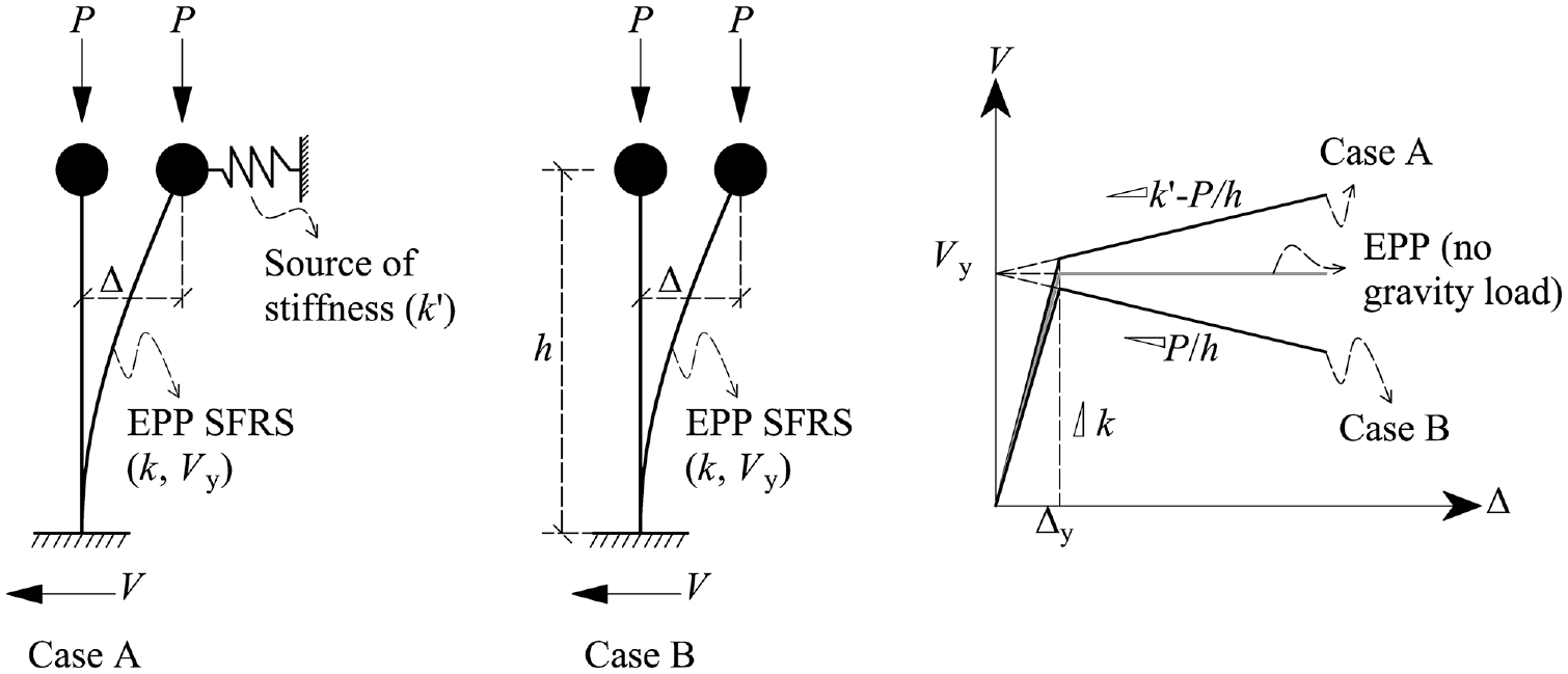
P-delta effects in stability-enhanced and conventional EPP SDOF systems.
To meet these guidelines (i.e. proposed by Hariri) a robust source of lateral story shear stiffness is required. Although several structural components, such as column continuity, continuous splicing of gravity columns, and the partial fixity of the beam–column connections in braced frames, can develop lateral story shear stiffness, their contribution is not robust throughout the seismic loading, especially for long-duration earthquakes. Tremblay (2018), for example, demonstrated that splicing the columns to develop continuity has negligible contribution to lateral story shear stiffness in story mechanisms involving two or more stories. Non-pinned beam–column connections in braced frames introduce lateral stiffness that decays with the number of cycles and drift amplitude, rendering them inefficient, especially for long-duration earthquakes.
Focusing on the seismic component of the demand, past studies (Attard, 2007; Bashir Pour, 2022; Bergman and Hanson, 1993; Chang and Lin, 2004; Chang et al., 1992, 1993, 1995; Christopoulos and Montgomery, 2013; Dicleli and Mehta, 2007; Dong et al., 2016, 2018; Kang and Tagawa, 2013; Mehrabi et al., 2017; Pu and He, 2022; Shu et al., 2023a, 2023b; Smith and Willford, 2007; Zhang et al., 1989) have underscored the effectiveness of integrating supplemental dampers, including viscous and viscoelastic (VE) dampers, to enhance the energy dissipation capacity of steel SFRSs. These dampers introduce additional velocity-dependent force, thereby augmenting the structures’ damping, which tends to be relatively low in steel buildings (Christopoulos and Montgomery, 2013; Pu and He, 2022; Smith and Willford, 2007). VE dampers, specifically, consist of multiple layers of engineered high-damping solid polymers bonded to multiple steel plates. These steel plates extend from one side in an alternating pattern, forming two groups, each connected to a structural casing via element end-connectors (Montgomery et al., 2021). One key difference between the viscous and VE dampers is that VE dampers induce a displacement-dependent elastic spring force in parallel to the velocity-dependent damping force. This additional force induces positive elastic stiffness that can be used to increase the post-elastic stiffness in P-delta vulnerable SFRSs.
Considering the damping effect, past studies (Bashir Pour, 2022; Chang et al., 1993, 1995; Mehrabi et al., 2017; Shu et al., 2023b; Zhang et al., 1989) demonstrate that incorporating VE dampers in steel frames reduces floor accelerations and peak interstory drifts. Specifically, Shu et al. (2023a) reported that this reduction can reach 20% and 30% for floor acceleration and peak interstory drifts, respectively, when numerically tested using a 16-story moment frame. Furthermore, these dampers can be seamlessly implemented in new or existing steel frames using various application forms, such as the beam–column connection rotational damper (Shu et al., 2023a) and self-centering systems with VE braces (Fang et al., 2022; Lin et al., 2022; Zhang et al., 2022).
VE dampers in steel structures in past studies primarily targeted enhancing the seismic performance in steel moment frames by increasing the inherent damping of these flexible structures. However, the use of these dampers in braced frames was limited. Shu et al. (2023b) conducted a study to assess the enhancement of incorporating the rotational VE dampers on a 4-story steel BRBF. It was concluded that replacing the pinned beam–column connections of the BRBF with rotational VE dampers can increase the inherent damping by approximately 3%, reaching a total damping ratio of more than 5%. Furthermore, this incorporation has a significant impact (i.e. 35% reduction) on the peak interstory drifts under frequent earthquakes stemming crustal seismic sources.
Almost all the above-mentioned studies relied on the damping effect in designing the VE dampers to enhance the seismic performance of steel SFRSs, where the VE elastic spring forces were neglected or considered as a secondary effect. This article presents a practical approach for integrating secondary lateral story shear stiffness into steel BRBFs employing the VE dampers designed concerning their induced spring elastic forces while considering their damping contribution as a secondary effect. The novel system, referred to herein as VE-BRBF, consists of a BRBF with an inverted-V bracing configuration with a VE damper vertically installed at apex of the beam–brace connections on each story. The elastic stiffness of the damper is tuned at every story, as proposed by Hariri (2023; Hariri et al., 2024a, 2024b). The added dampers in the proposed VE-BRBF system offer dual benefits. The primary benefit is that it introduces the recommended secondary stiffness to mitigate P-delta effects and enhance the recentering capability to control the residual drifts. The secondary benefit is that it provides supplemental damping, which improves energy dissipation, promotes inherent damping, mitigates vibrations during earthquake motions, and improves the reliability of the numerical analysis (Smith and Willford, 2007).
The adequacy of the proposed system is assessed in 10- and 20-story office prototype buildings located in Vancouver, BC, on stiff soil. The assessment involves nonlinear response history analysis (NLRHA) utilizing ground motions from three seismic sources: crustal, deep in-slab, and subduction interface.
For comparison, two distinct SFRSs are considered in each building, with SFRSs in each direction evaluated individually, as permitted in NBC 2020 for buildings with symmetrical layouts subjected to earthquakes with 2% in 50 years probability of exceedance. In the X-direction, conventional BRBFs are employed, designed according to the classical seismic stability provisions outlined by NBC (2020). In this design approach, height limitation is overlooked, and the design force demand on the BRBs is amplified using an inelastic stability coefficient.
Conversely, in the Y-direction, the proposed VE-BRBFs are utilized. These systems feature BRB elements with baseline strength (i.e. unamplified) and incorporate VE dampers. The selection of these dampers is primarily based on their elastic stiffness, with the damping effect considered secondary. This criterion results in limited added damping, as higher damping improves the seismic response, but may adversely affect the recentering mechanism, increasing the residual drifts (Karavasilis and Seo, 2011; Seo et al., 2014).
Description and design of VE-BRBFs
The proposed VE-BRBF consists of a conventional BRBF in a V or an inverted-V bracing configuration with VE damping elements added at every level at the beam–brace intersections. For the VE length to accommodate the story height geometry, two hollow structural section (HSS) members are added, one at each side, bolted to the VE element and welded to the beam gusset plates. Figure 2a and b presents the VE-BRBF illustrating the V and inverted-V bracing configurations, respectively.
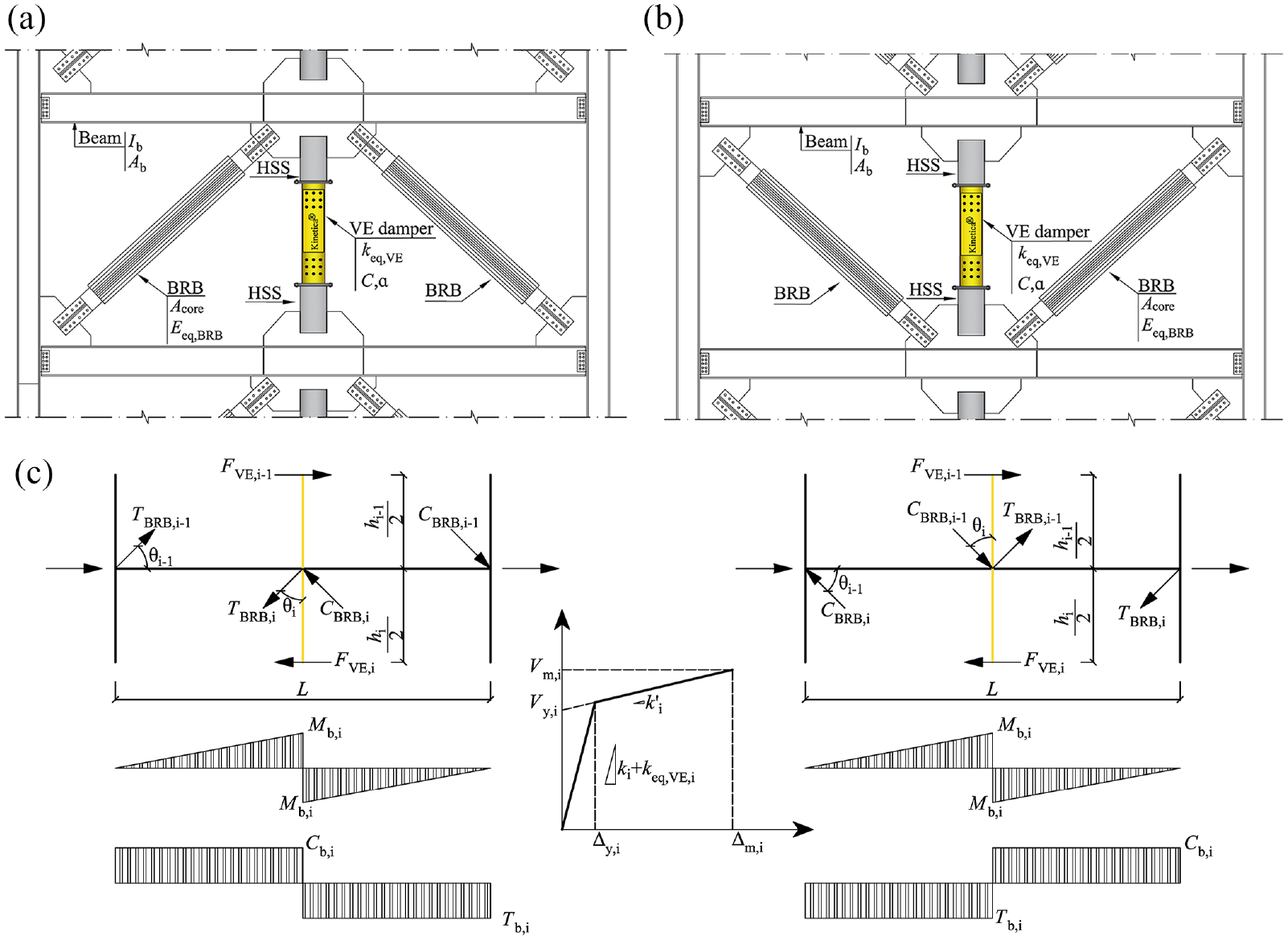
VE-BRBF. (a) V bracing configuration. (b) Inverted-V bracing configuration. (c) Analytical models.
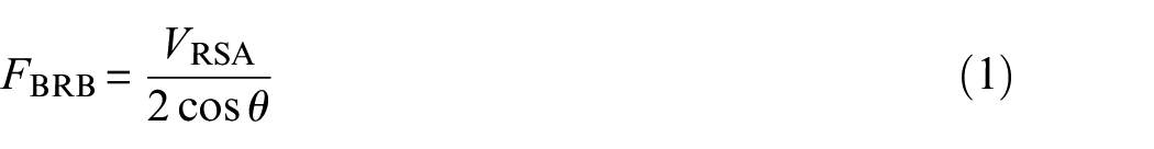
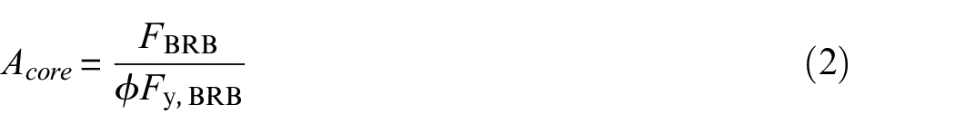
The BRB elements in the VE-BRBF frame are sized based on the design story shear assigned to the frame obtained from the classical analysis (VRSA) (e.g. response spectrum analysis or equivalent static force), where the BRB design force (FBRB) and the BRB core area Acore are obtained using equations 1 and 2, respectively, where Fy,BRB is the yield strength of the BRB core element steel, ϕ is the strength reduction factor (taken as 0.9), and θ is the BRB angle as illustrated in Figure 2c. The subscript i in the figure and equations denotes the story, in cases where story differentiation is necessary:
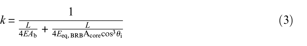
Once the BRBs are designed, the lateral story shear stiffness (k) can be calculated using equation 3, assuming BRBs and axial stiffness of the connected beam are in series. This assumption is conservative and aligns with the absence of a rigid diaphragm, where the beam acts as a conductor for the BRB stiffness. In the equation, Eeq,BRB refers to the equivalent modulus of elasticity, accounting for the rigid end connections of the BRB elements, as provided by the BRB manufacturer. L is the span length, and Ab is the beam cross-sectional area, as shown in Figure 2a and b.
The contribution of the VE dampers to the lateral story shear stiffness is omitted from equation 3, as this equation accounts only for the primary system (BRBs) and will be used to size the dampers utilizing 2%–3% of k, as discussed later in this section. Regarding the effect of the VE dampers’ stiffness on the base shear calculation (i.e. RSA), their added stiffness should be considered. However, compared with the elastic stiffness of the primary system, the dampers’ contribution may have a negligible effect on the base shear. In this article, the VE-BRBF design is not sensitive to minor variations in fundamental periods, as the buildings are tall enough to fall within the period range associated with the minimum design base shear, which is further discussed in the article:
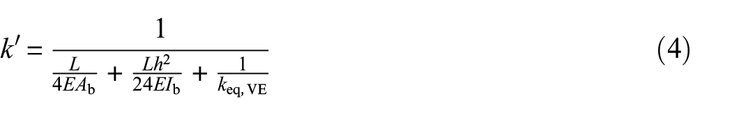
To comply with the P-delta mitigation approach proposed by Hariri (2023; Hariri et al., 2024a, 2024b), the VE elements are sized so that the post-elastic story lateral shear stiffness (k′) is equal to a target stiffness (kTarget) computed as P/h + (0.02 to 0.03)k, where P/h is the story negative stiffness and k is the elastic story shear obtained from equation 3. The post-elastic story shear stiffness (k′) is obtained using equation 4, where Ib is the beam cross-sectional moment of inertia and keq,VE is the equivalent shear stiffness of the VE element that takes into account the length of the connecting HSS members and is obtained from damper manufacturers, such as Kinetica (2024). Although the primary source of post-elastic stiffness is the VE damper, the axial and flexural stiffness of the beam are also included in the equation since the damper is connected to the beam in series. It is noteworthy that the beam’s axial and flexural stiffness are significantly higher than that of the damper:
To design the frame’s structural members, such as beams and columns, in accordance with the capacity design principles adopted in Canada, the probable force developed in the BRBs, and dampers must be assessed. For BRBs, the tension and compression probable forces (i.e. TBRB and CBRB) are obtained by amplifying the BRB yield force (Py, BRB in equation 5) with the BRB strength adjustment factors (ω and β), as presented in equations 6 and 7, respectively, where Ry is the probable to nominal strength adjustment factor:


For VE dampers, the maximum induced force (FVE) can be calculated using equation 8, which sums the spring and damping shear forces, FVE,Spring and FVE,Damping, respectively. The spring and damping forces can be determined using equations 9 and 10, where keq,VE is the equivalent damper stiffness, accounting for the sizes of the connecting HSS members. Δm represents the maximum story drift, v is the story velocity, and C is the damping coefficient:


Hence, the maximum story shear capacity (Vm) for story i, as presented in Figure 2c, can be calculated as the sum of the shear forces developed in the BRBs (Vm,BRB) and the VE damper (FVE) in that story, as presented in equation 12:


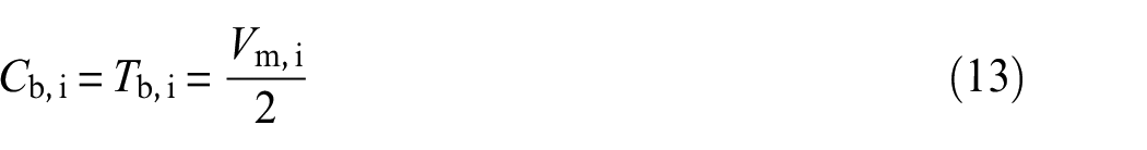
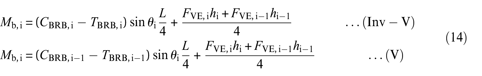
The compression and tension axial force demands, as well as the flexural moment on the beam in story i (i.e. Cb,i, Tb,i, and Mb,i, as presented in Figure 2c) can be calculated using equations 13 and 14 for both the V and inverted-V bracing configurations:
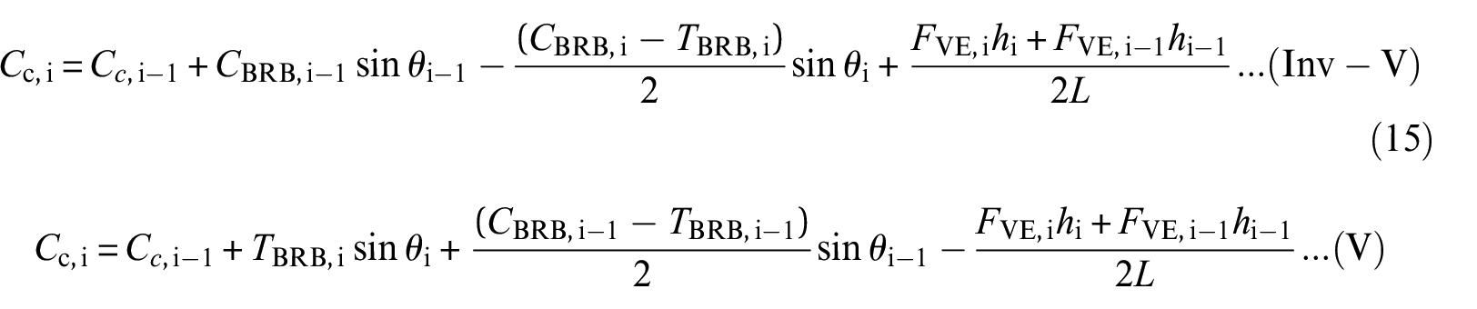
Finally, the compression force demand on the column in story i can be obtained by summing the force demand from the upper story (i.e. i− 1), the connected BRB compression force, and the connected beam reaction, as presented in equation 15. It is worth noting that the difference between the compression and tension strength of the BRB imposes a slight upward vertical displacement demand on the VE damper. This is counteracted by the downward deflection of the beam under gravity loading, resulting in a negligible net vertical displacement demand on the damper. However, due to the bidirectional nature of the VE layers, this minor deformation, as long as it remains within the specified tolerance, does not compromise the damper’s performance:
It is important to note that the proposed equations represent a conservative design approach, assuming that the BRBs and VE dampers simultaneously develop their maximum probable forces across all stories and at the same loading time step. This design approach results in a significant increase in braced frame member sizes, primarily due to the design moment demand imposed by the dampers; however, this assumption will be further assessed in this study.
Numerical analysis
Description of prototype buildings
This study considers the response of 10- and 20-story office prototype buildings in Vancouver, BC, situated on a soil characterized by an average shear wave velocity (V30) of 500 m/s, corresponding to stiff soil (Class C). The 10- and the 20-story buildings comprise symmetrically arranged six bays, each measuring 9 m, in both principal directions. Each story in both buildings has a height of 4 m, except for the ground level, which is 4.5 m tall.
To facilitate a comparative analysis between the different seismic stability provisions, two distinguished SFRSs are employed, one in each principal direction. In the X-direction, conventional BRBFs were designed respecting the strength amplification approach per the NBC 2020 using the inelastic stability coefficient. Conversely, the proposed VE-BRBF is employed in the Y-direction, incorporating ductile members (i.e. BRBs) designed with baseline strength (unamplified) and VE damping elements incorporated at every story with elastic stiffness tuned along buildings’ heights as proposed by Hariri (2023; Hariri et al., 2024a, 2024b).
The SFRSs in the 10-story buildings in both directions incorporate four single-bay braced frames, two on each side and positioned at the building’s perimeter. The SFRSs in the 20-story building incorporate two double-bay braced frames positioned in center bays at the perimeter on each side. Figures 3 and 4 illustrate the building layouts, SFRS framing configurations, and design gravity loads.
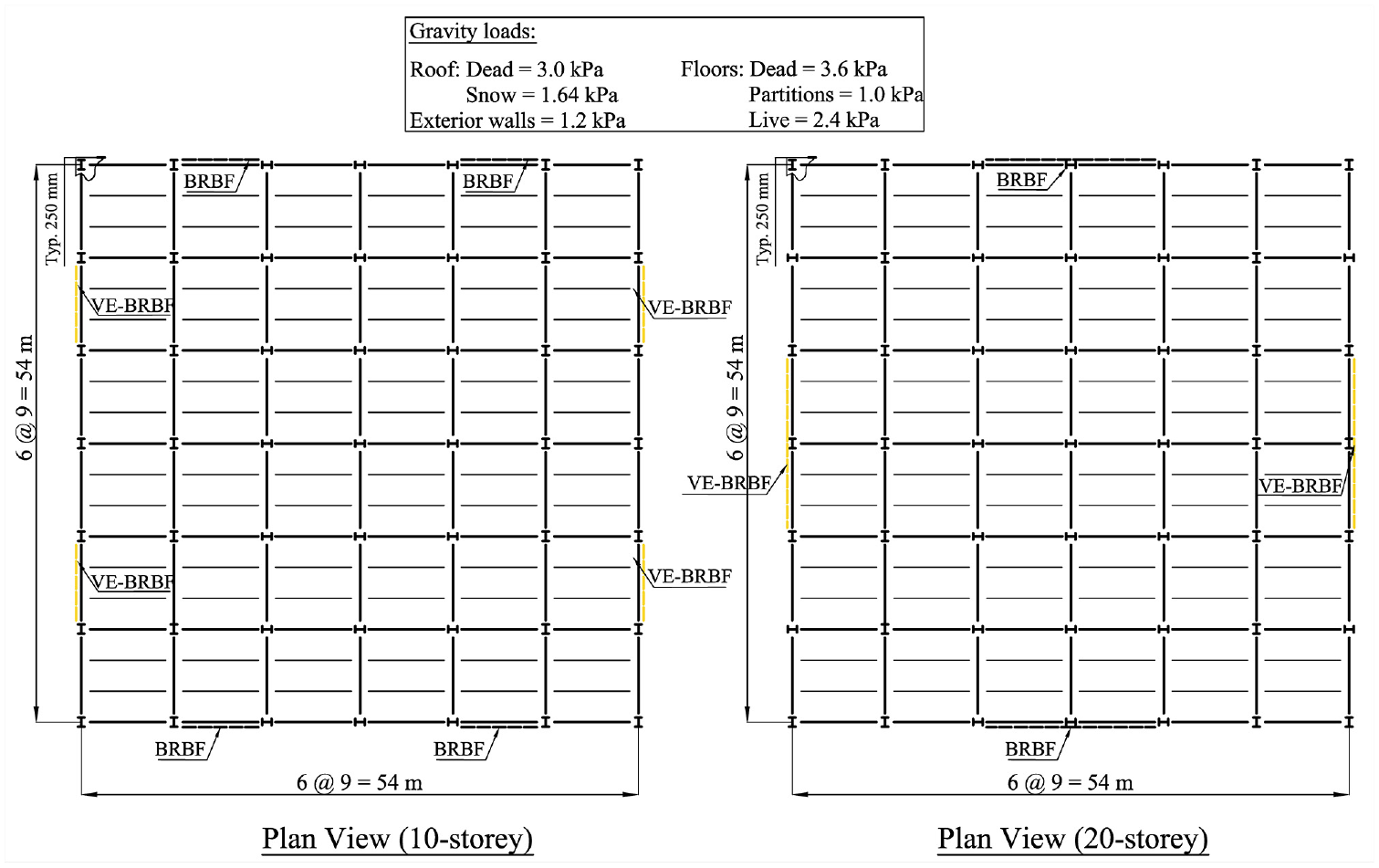
Prototype building layouts and gravity design loads.
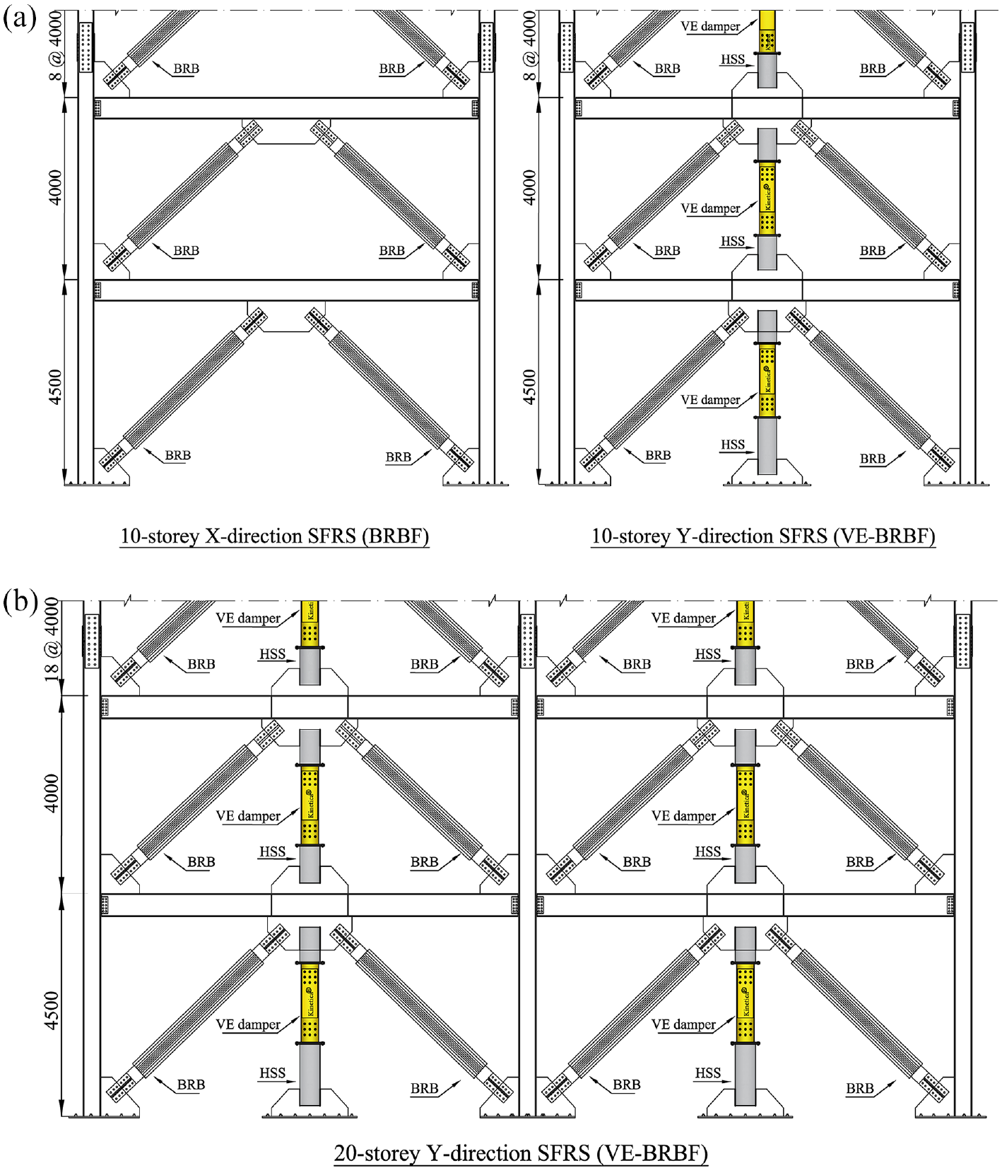
SFRS layouts. (a) 10-story (X- and Y-directions). (b) 20-story (Y-direction)
Design provisions—seismic
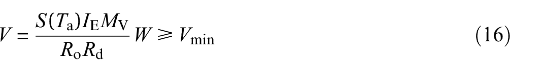
In NBC (2020), the design base shear is calculated, for each direction, using equation 16, where S is the spectral acceleration at the fundamental period Ta. IE, Mv, Ro, and Rd are the importance, higher mode, overstrength, and ductility adjustment factors, respectively. W is the total seismic weight, and Vmin is the minimum base shear quantified as the design base shear V at a 2-s period. For office buildings in this study, W is calculated using a D + 0.25 S load combination, and for BRBF in Seismic Category SC4, IE, Mv, Ro, and Rd are taken as 1, 1, 1.2, and 4.0, respectively, as prescribed in NBC:
NBC 2020 stipulates calculating the spectral acceleration (S) from the 2% in 50 years uniform hazard spectrum (UHS) (Figure 7), where the fundamental period Ta can be taken as the first dynamic period T1 obtained from dynamic modal eigen analysis with an upper limit of 0.05hn, where hn is the building’s total height. In this study, the base and story shears are obtained using multi-mode response spectrum analysis (RSA), where the base shear VRSA is scaled, when smaller, to match the 20% reduced designed base shear obtained from equation 16, as permitted by NBC for buildings with no irregularity.
NBC 2020 also stipulates that story drifts obtained from RSA must be scaled to get the elastic drift (Δf), as outlined for the VRSA, and amplified using RoRd to get the inelastic drift and compare it for every story against the 2.5%h limit. Torsional effects are ignored, as permitted in NBC 2020, for buildings with the center of mass coinciding with the center of rigidity and subjected to earthquakes with a probability of 2% in 50 years. Similar recommendations are given in past studies (Humar et al., 2003; Pettinga et al., 2007) for buildings with symmetrical layouts when inelastic behavior is expected.
Design provisions—stability
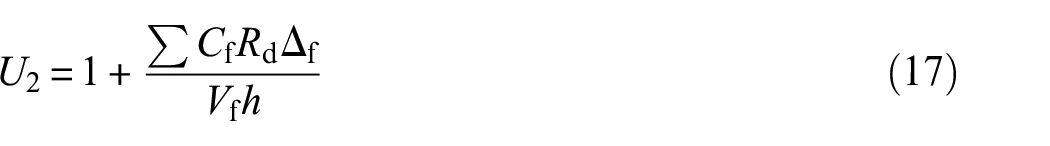
The NBC (2020) and the Canadian Steel Design Standard (Canadian Standard Association (CSA) S16:24) define an approach coupled with specific measures to consider P-delta effects in seismic design. Specifically, NBC adopts the classical approach of amplifying the story design shear force demand using a factor (U2) derived based on the inelastic stability coefficient. Equation 17 outlines this amplification factor, where ΣCf represents the gravity load calculated using the D + 0.5 L + 0.25 S load combination, Δf signifies the elastic story drift, Rd denotes the ductility factor, h stands for the story height, and Vf represents the baseline (unamplified) story shear. For steel SFRSs, the CSA S16:24 defines two thresholds for utilizing the NBC strength amplification factor U2. Stories with U2 less than 1.1 require no amplification, while those exceeding 1.4 necessitate redesign:
In addition to the story shear amplification, NBC 2020 imposes additional stability-related provisions on BRBFs in SC 4, such as the 40-m height limitation and the minimum design base shear (Vmin). However, despite these stringent requirements, the structural commentary of NBC 2020 acknowledges that these measures, including the story shear amplification, do not guard against dynamic instability in cases of significant inelastic deformation, particularly when the ductility is concentrated in a few stories.
Hariri (2023; Hariri et al., 2024a, 2024b) defines an alternative approach to addressP-delta effects in seismic design. This approach allows for the use of baseline strength (i.e. unamplified) with relaxed height limitations for SFRS coupled with systems capable of inducing lateral story shear stiffness equal to or greater than the negative stiffness ofP-delta effects plus 2%–3% of the elastic story shear stiffness, maintained for a story drift of at least 2.5% of the story height.
Design of SFRSs
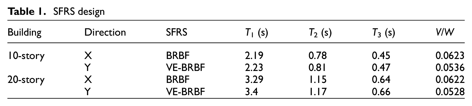
In this study, the SFRSs in the X-direction of the prototype buildings (i.e. BRBFs) are designed adhering to the classical seismic stability provisions prescribed in NBC 2020 and CSA S16:24, except that the imposed height limitation is overlooked (buildings are 40.5 and 80.5 m height). In contrast, SFRSs in the Y-direction (i.e. VE-BRBFs) are designed adhering to the novel stability guidelines proposed by Hariri, where the VE dampers are incorporated and designed to induce the prescribed secondary lateral story shear stiffness and maintain it for the stipulated story drift. Table 1 presents the seismic design details, including the design base shear normalized for the total seismic weight and the dynamic periods (T1, T2, T3) for the buildings under study in both directions. It is noteworthy that all studied SFRSs are governed by the minimum base shear (i.e. Vmin in equation 16) due to their fundamental periods exceeding the 2-s threshold, indicating that the base shear is insensitive to slight changes in lateral stiffness, and that the dampers’ added stiffness can be neglected during design.
SFRS design
The ductile members in the X-direction BRBFs (i.e. BRBs) are sized using equations 1 and 2, with the frame assigned shear force amplified using the U2 factor and considering a yield strength of the BRB core elements of Fy,BRB = 345 MPa. Beams and columns are conventionally designed using capacity design principles employing the probable BRB yielding strengths with Ry of 1.11 and amplified using the tension and the compression strain hardening adjustment factors ω and β of 1.4 and 1.1, respectively.
In the Y-direction SFRSs, the BRBs are sized using equations 1 and 2 utilizing the baseline frame shear force (i.e. not amplified by U2). The VE dampers are selected based on their induced story shear stiffness (k′), calculated using equation 4, where a targeted secondary lateral story shear stiffness (k′Target) is P/h + 0.02k is considered, where k is obtained from equation 3. Beams and columns are capacity designed respecting the probable yielding strength of the ductile members (i.e. BRB) amplified with ω and β as well as VE elements induced force demand (i.e. FVE) at the designated story drift (Δm of 2.5%h) using equations 13–15. The design overlooked the velocity-dependent damping component of VE forces (i.e. FVE,Damping), given the small damping effect expected as VE elements are sized based on their stiffness. However, this assumption will be validated and assessed.
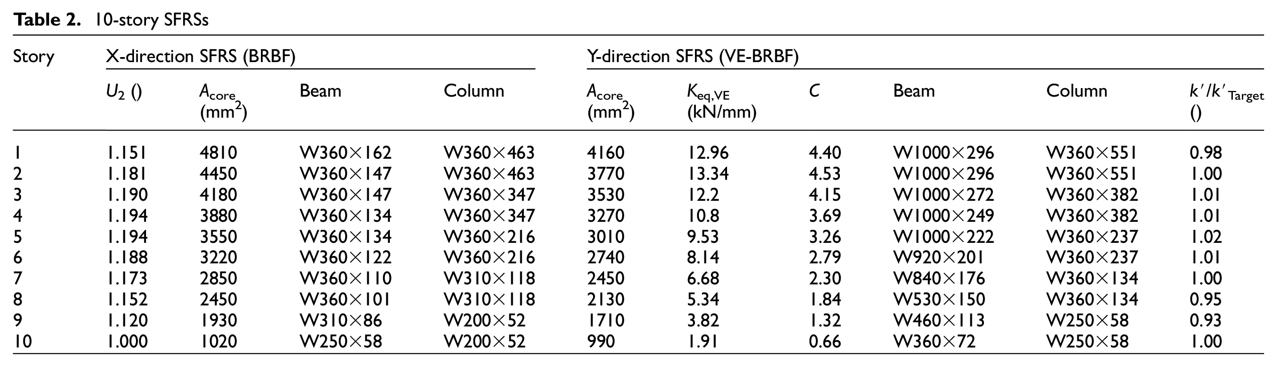
For beams and columns in the SFRSs in both directions (i.e. X and Y), ASTM A992 steel with Fy of 345 MPa is utilized. The beams are designed as beam–column elements assuming they are laterally supported out-of-plane at beam–brace intersections. As stipulated in CSA S16, beams are designed assuming BRBs do not provide in-plane support to beams under gravity loads. Columns are oriented in their strong direction and assumed laterally supported in both directions at all story levels. In addition to the axial force demands obtained from capacity design, columns are designed considering a moment of 0.2 Mp, as stipulated in CSA S16 for braced frames, where Mp is the plastic moment. Given the substantial axial demand resulting from the assumption that all BRBs develop the full kinematic and isotropic strain hardening while yielding simultaneously, no suitable W-section was identified for the columns situated in the first four floors of the 20-story VE-BRBFs. However, the largest section available, W360×1299, is utilized and its axial force demand will be verified, as the assumption of simultaneous yielding with maximum strain hardening in all levels has been proven conservative (Richards, 2009; Shrestha and Bruneau, 2018). Tables 2 and 3 present the design details for SFRSs in both directions in the 10- and 20-story buildings, including beam–column-cross sections, U2 factor for the X-direction SFRSs, and the induced-to-targeted stiffness ratio (k′/k′Target) for the Y-direction SFRSs. The tables indicate an increase in beam and column sizes for the Y-direction SFRS (i.e. VE-BRBF) when compared with the conventional SFRS in the X-direction, which results in an increase in braced frame tonnage of 30% and 40% in the 10- and 20-story buildings, respectively. This increase is primarily due to the capacity design principles adopted in Canada, which require BRBF beams and columns to be designed under the assumption that dampers and BRBs simultaneously develop their maximum probable forces. The conservatism of this assumption is assessed in this study.
10-story SFRSs
20-story SFRSs
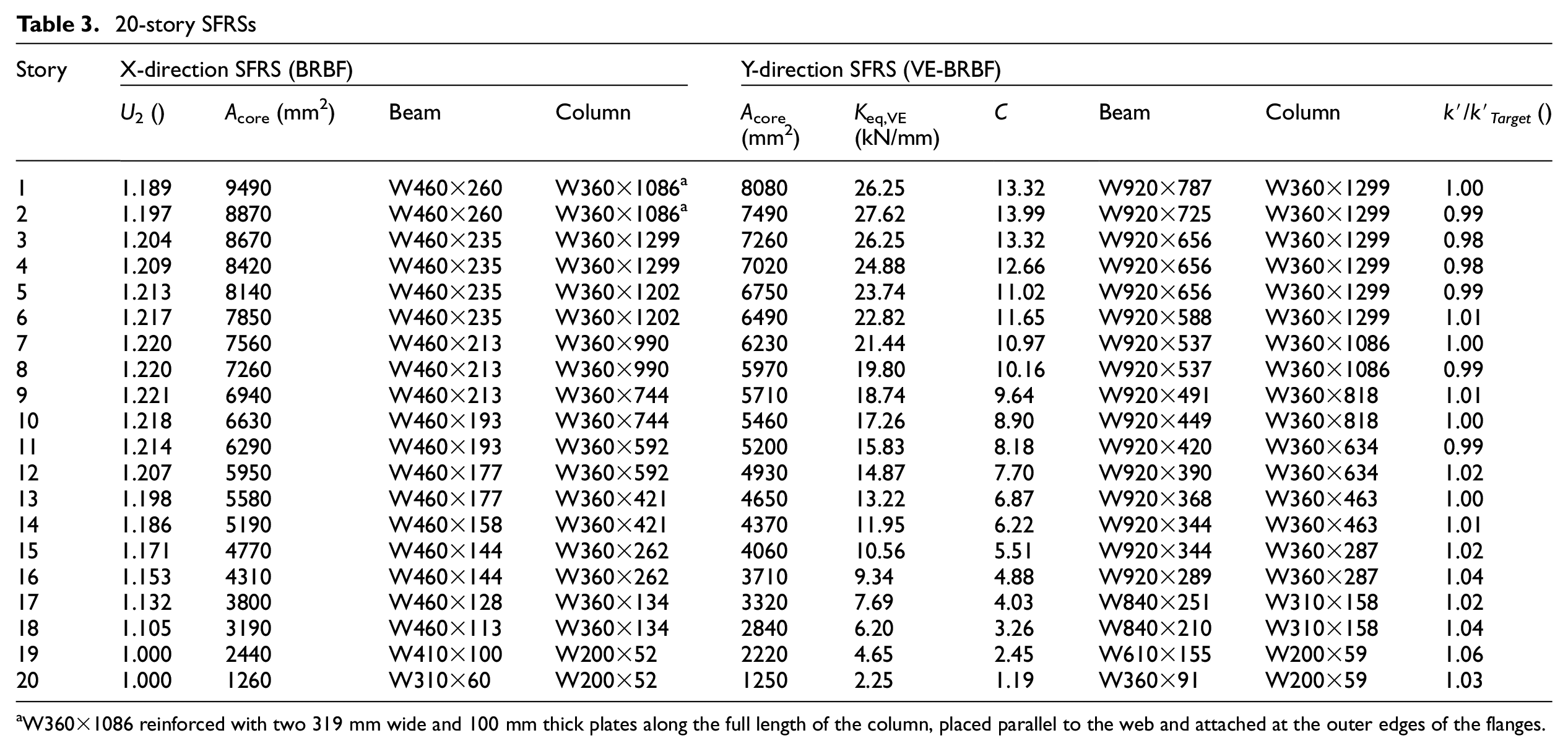
aW360×1086 reinforced with two 319 mm wide and 100 mm thick plates along the full length of the column, placed parallel to the web and attached at the outer edges of the flanges.
Numerical modeling
The SFRSs in both orthogonal directions of each prototype building are individually modeled using the OpenSees platform, employing three-dimensional frames with corotational geometric transformation. In the case of the 10-story building, a single-bay frame is utilized, representing a quarter of the building mass and gravity loads for each direction. For the 20-story building, a double-bay frame is modeled to represent half of the building mass and gravity loads. Torsional effects are omitted during analysis, aligning with guidelines of the NBC Structural Commentary for symmetrically laid out buildings (i.e. centers of mass and rigidity coincide) subjected to earthquakes with a 2% probability of occurrence within 50 years. This omission is justified in the commentary by the expectation of inelastic deformation of the SFRS ductile members under such seismic conditions. Similar conclusions are also given by Humar et al. (2003) and Pettinga et al. (2007).
The BRBs in the frames of both directions are modeled using truss elements with a cross-sectional area of Acore and an equivalent module of elasticity Eeq,BRB taken as 1.5 times the steel module of elasticity in the used steel (E = 200 GPa), as suggested by Robinson (2009). Zsarnóczay BRB material (steel4) is used for the BRB elements utilizing parameters calibrated using machine learning algorithms in MATLAB (i.e. fminsearch) (Hariri and Tremblay, 2021), based on cyclic and seismic signal tests performed on full-scale specimens (Dehghani and Tremblay, 2018) that match the dimensions and bracing configurations of the prototype buildings. The resulting hysteresis calibration is presented in Figure 5.
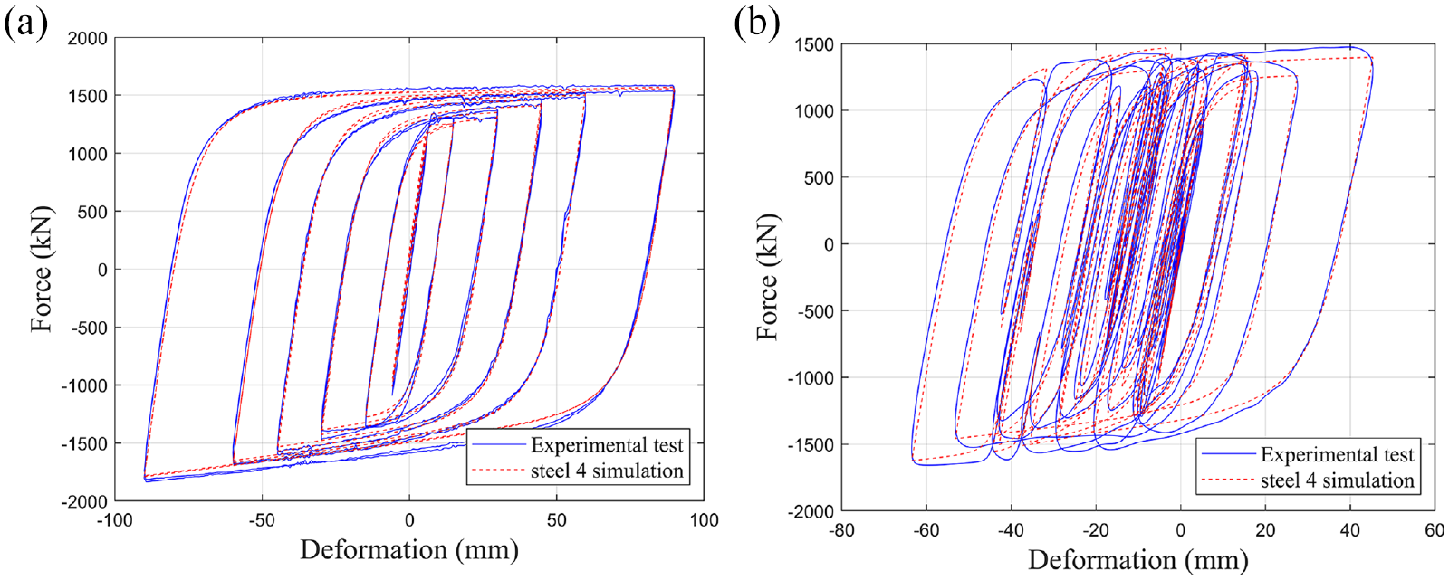
Calibration of steel4 material. (a) Cyclic test. (b) Seismic signal.
For frames in the Y-direction (i.e. VE-BRBFs), the VE dampers, along with their mounting HSSs, are simulated using two-node link elements with a shear location at mid-height (Figure 6) and incorporating two materials acting in parallel to simulate the Kelvin–Voigt material. The first is assigned an elastic material with a stiffness of keq,VE (Tables 2 and 3) to simulate the elastic spring force, and the second is a viscous material which is used to simulate the damping force with the C parameter, as presented in Tables 2 and 3 and a constant velocity exponent α of 1, as provided by the manufacturer (Kinetica, 2024).
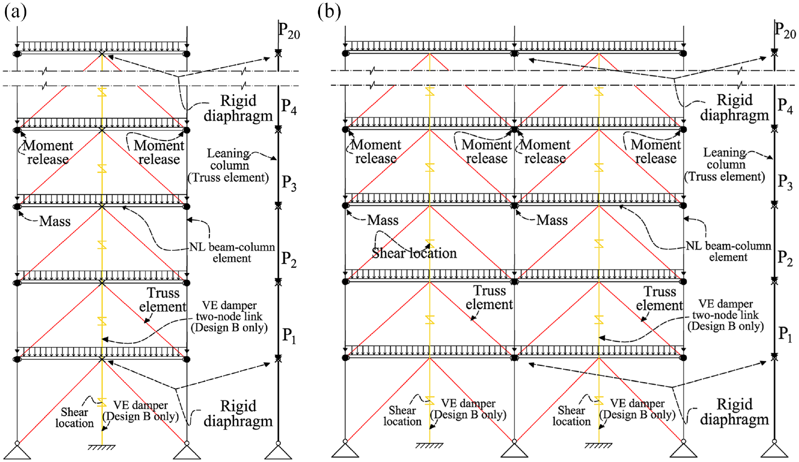
Numerical models. (a) 10-story. (b) 20-story.
The beams and columns are modeled using eight beam–column elements utilizing four integration points with fiber cross-sections discretized and pre-stressed to account for residual stresses using the Galambos and Ketter (1959) pattern. The beams are pinned-supported on the columns, and columns are continuously-spliced every other floor at a height of 1.2 m. Giuffré–Menegotto–Pinto material (steel02) with default parameters and an expected yield strength RyFy of 385 MPa is used. Initial imperfections were included using a predefined node geometry utilizing the sine function with a maximum imperfection of 0.2% of the length at mid-nodes.
Tributary masses are lumped and assigned to the column nodes at the floor level. Gravity loads, excluding those attributed to the frames, are lumped and assigned to the leaning column nodes, which are constrained to the frame mid-nodes at each story using rigid diaphragms (i.e. the beam middle node for the 10-story frame and the mid-column node for the 20-story frame), as illustrated in Figure 6.
Rayleigh damping with coefficients proportional to mass and current-step stiffness is employed, determined from modal analysis using the first and third modal periods, obtained after applying the gravity loads and utilizing a 3% damping ratio. Figure 6 illustrates the modeling assumptions.
Ground motions
Twenty-two historical earthquake records are selected and scaled to match the 5% damped, 2%-in-50-years UHS for Vancouver, BC, on Soil Class C, defined as the target spectrum (Figure 7). These records are divided into two suites, each consisting of 11 records, in accordance with NBC 2020 guidelines. Suite I includes crustal and in-slab records, while Suite II comprises subduction interface records. The records for both suites are selected based on their magnitude (M) and distance (R), over the relevant period range considering their contribution to the UHS as deaggregated by Halchuk et al. (2019), and bounded by the minimum upper and lower limits specified by NBC 2020.
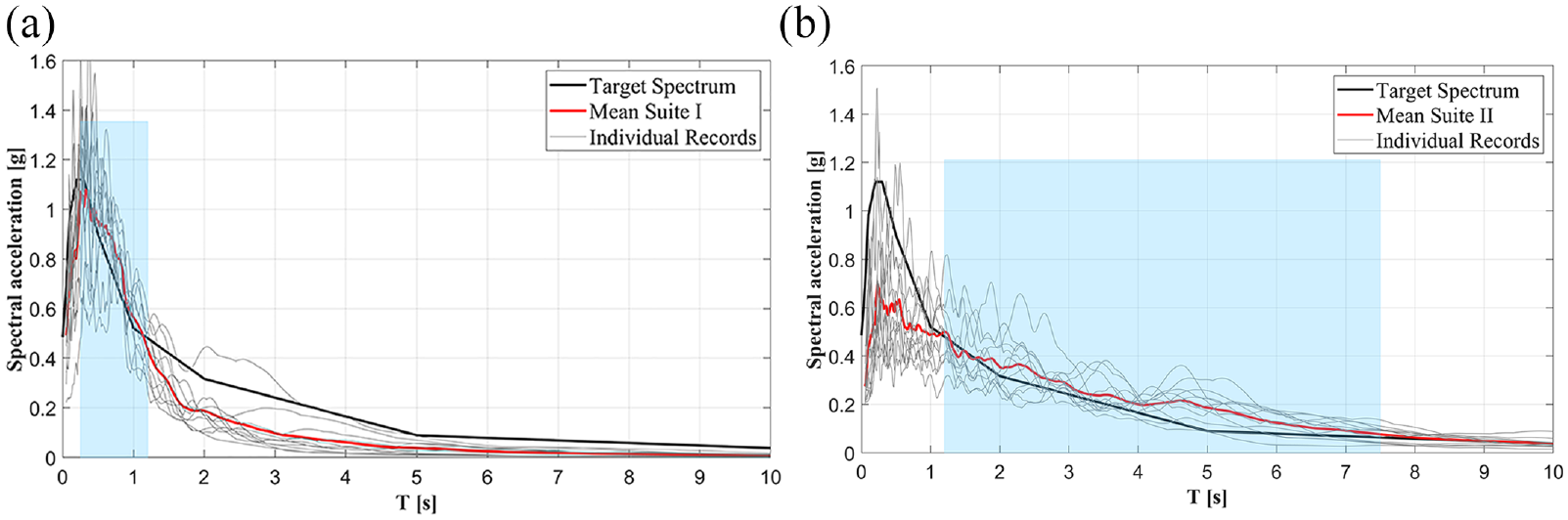
Selected ground motions. (a) Suite I. (b) Suite II.
NBC 2020 defines a minimum scaling period range with lower and upper boundaries of 0.15 T1 and 2 T1, respectively, where T1 represents the fundamental period of the structure. To accommodate both the 10- and 20-story buildings using the same ground motions, a broader scaling range was utilized. The lower bound (0.15 T1) was derived from the T1 of the 10-story building (2.19 s), and the upper bound (2 T1) was based on the T1 of the20-story building (3.4 s), resulting in a scaling range of 0.32–6.8 s. Figure 7a and b shows the target design spectrum, the scaling period range, and the 5%-damped response spectra of the scaled records for each suite.
Based on the NBC minimum scaling limits and each suite’s contribution period range to the UHS (Halchuk et al., 2019), Suite I was assigned a period range of 0.32–1.0 s, while Suite II was assigned a period range of 1.0–6.8 s. Tables 4 and 5 present the characteristics of the records and their scaling factors for each suite.
Characteristics of the input ground motion considered for Suite I
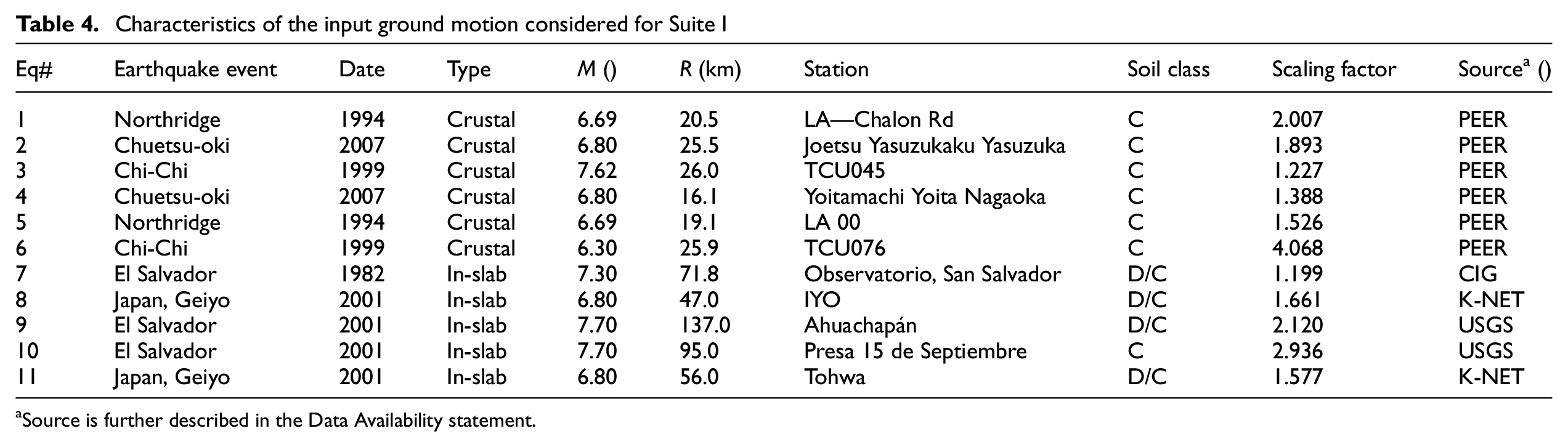
aSource is further described in the Data Availability statement.
Characteristics of the input ground motion considered for Suite II
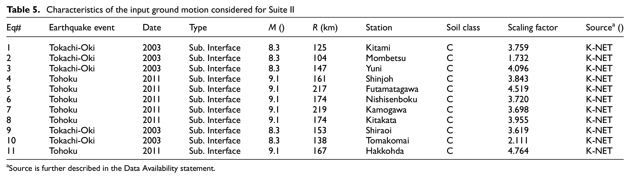
aSource is further described in the Data Availability statement.
Analysis results
NLRHA was conducted on the developed frame numerical models in OpenSees using implicit time integration scheme (i.e. Newmark-beta method with γ = 0.5 and β = 0.25), employing the selected and scaled ensemble of earthquake records. Each SFRS in every direction was analyzed individually. The analysis was prolonged to include 10 s of free vibration following each earthquake record to assess residual deformation and terminated when the story drift ratio exceeded 10%.
The acceptance criteria, as stipulated in NBC 2020, relied on evaluating the seismic demand (SD) curve, which represents the largest mean response from the two suites of records. The interstory drift ratio SD curve was required not to exceed 2.5%, while the residual drift ratio SD curve had to fall within the specified repair limit of 0.5%, as defined in prior studies (Erochko et al., 2011; McCormick et al., 2008). In addition, NBC stipulates that unacceptable response, such as dynamic instability, shall not occur.
Figures 8 and 9 depict the peak and residual interstory drift ratios along with the mean and SD curves for the SFRSs in both directions of the prototype buildings, respectively. Each figure is structured into two columns representing the studied buildings (i.e. 10- and 20-story) and two rows representing the direction (i.e. X and Y). The figures illustrate that under the crustal and in-slab earthquakes (i.e. Suite I), the stability provisions adopted in the Canadian design codes, which prescribe an amplification of the design story shear demand using inelastic stability coefficients, utilized in the X-direction SFRS (i.e. BRBF), led to peak interstory drift responses that met the criteria outlined in NBC 2020. However, they also resulted in residual drifts slightly exceeding the repair limit despite overlooking the imposed height limitation. In contrast, these provisions proved insufficient to mitigate instability/excessive drifting under the subduction interface records in both buildings. This inadequacy manifested in one instance of global instability (>10%) in the 20-story building and an SD drift curve exceeding the 2.5% limit for the 10-story building. In addition, the SD residual drift curve indicated irreparable damage for both buildings, where the SD curve exceeded 0.5% in several stories.
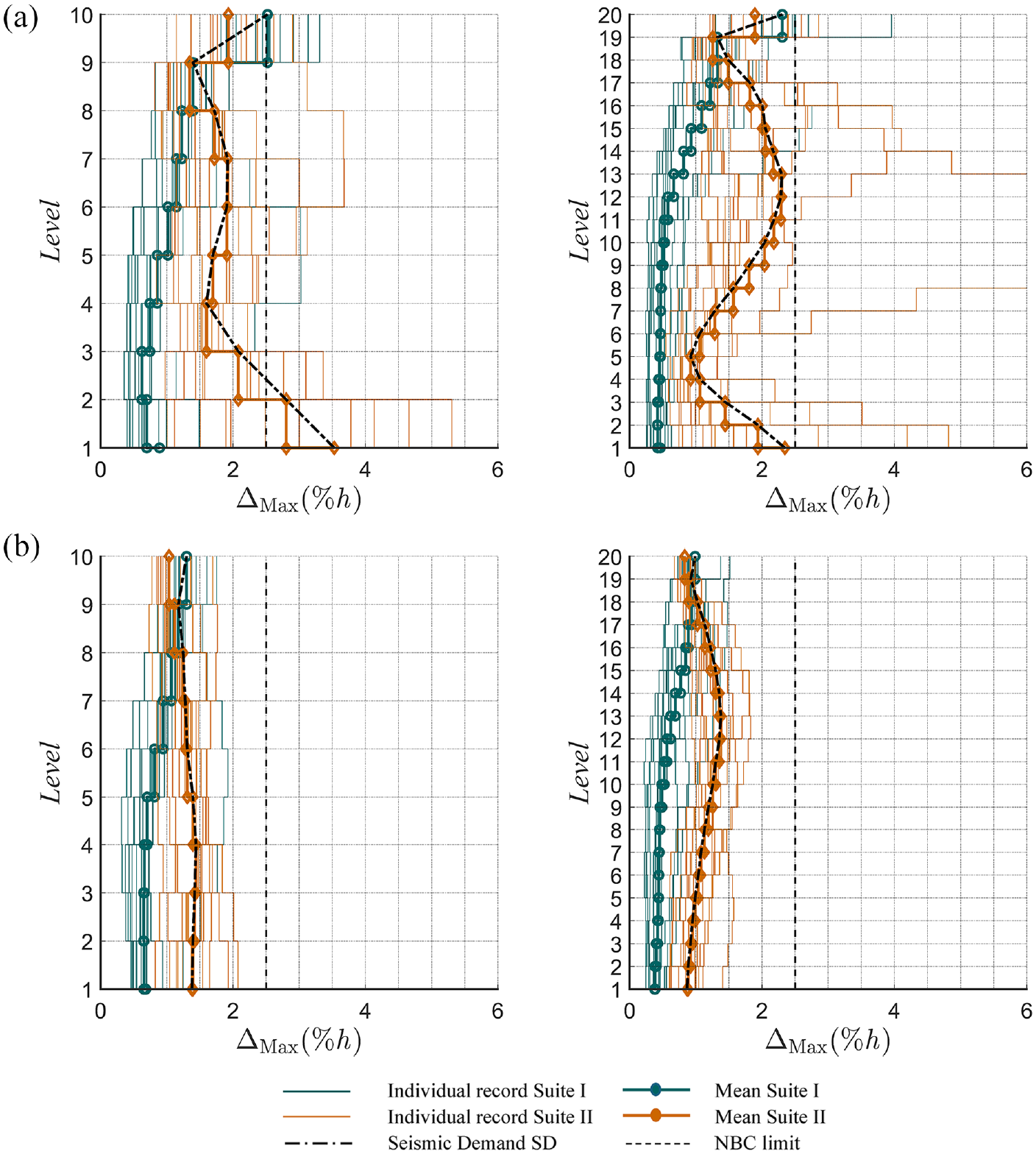
Peak interstory drift ratios of prototype buildings. (a) X-direction SFRS (BRBFs). (b) Y-direction SFRS (VE-BRBFs).
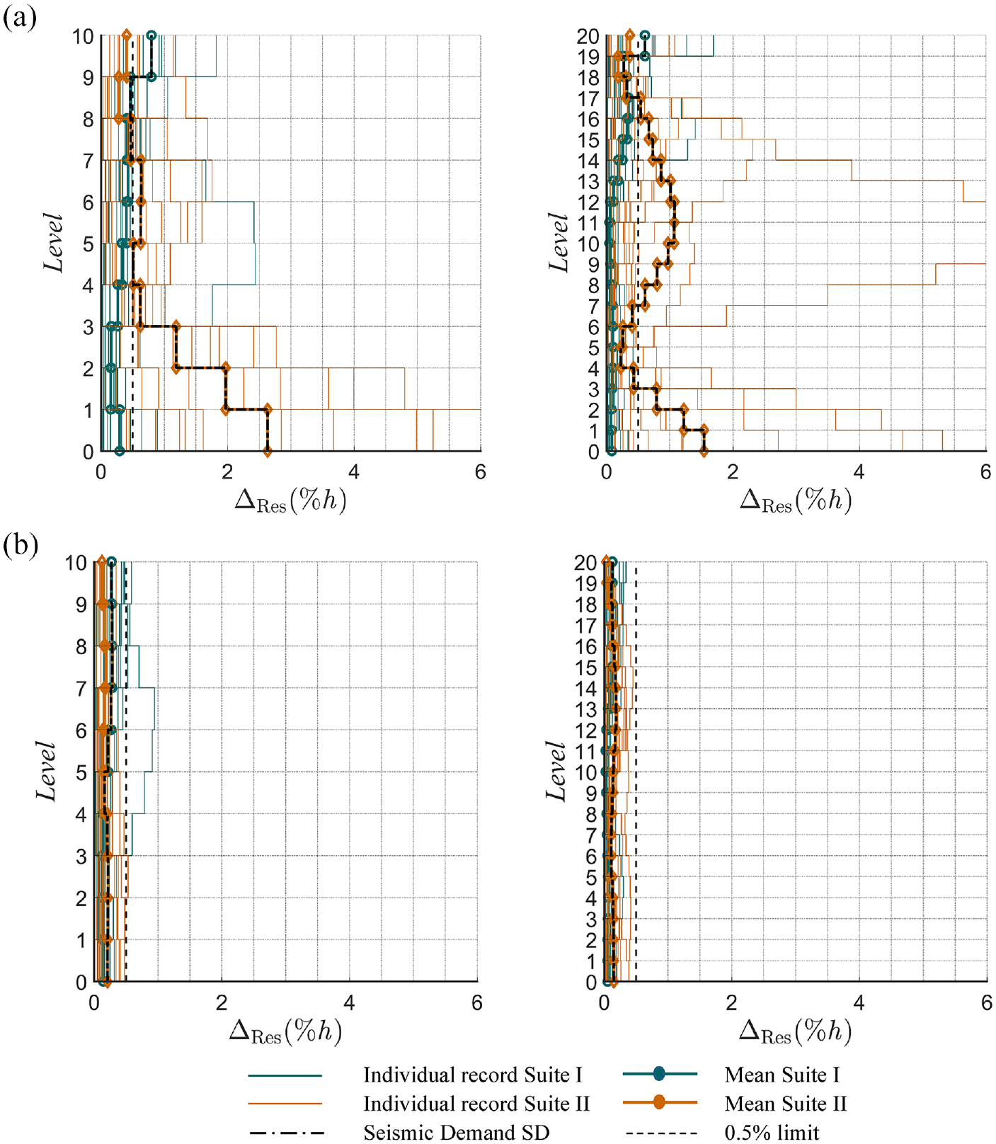
Residual interstory drift ratios of prototype buildings. (a) X-direction SFRS (BRBFs). (b) Y-direction SFRS (VE-BRBFs).
In contrast, the novel seismic stability provisions employed in the Y-direction SFRSs (i.e. VE-BRBF) incorporate post-elastic lateral story shear stiffness, as proposed by Hariri (2023; Hariri et al., 2024a, 2024b). This, combined with the damping effect of the VE-dampers, demonstrated seismic responses that complied with code requirements and repair limitations, delivering uniform drift distributions regardless of seismic excitation source or building height. The improved response can be attributed to the VE dampers’ ability to induce lateral story shear stiffness, which counteracts the negative stiffness caused by P-delta effects, as illustrated in the hysteretic responses of the first story in both directions presented in Figure 10. As a result, P-delta-induced drift ratcheting, excessive drift, and global instability were mitigated, even when utilizing baseline strength.
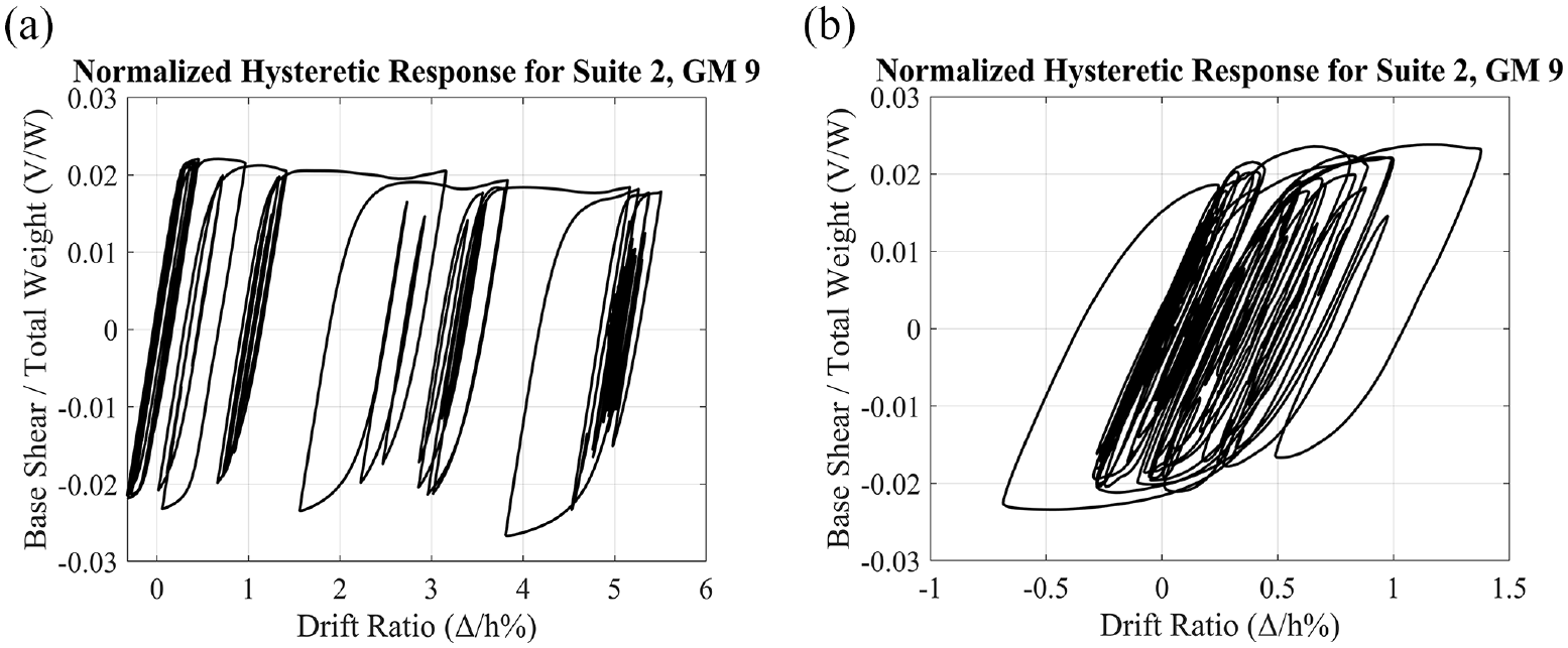
Hysteretic response of the first story frame. (a) X-direction SFRS (BRBFs). (b) Y-direction SFRS (VE-BRBFs).
Moreover, this additional stiffness enhances the efficiency of the primary SFRS (BRBs) in dissipating seismic energy. Unlike the X-direction SFRS, where BRBs must resist combined demands, the Y-direction SFRS (VE-BRBF) dissipates seismic energy without the added demands associated with P-delta effects. As illustrated in Figure 10, the recentering mechanism, combined with the mitigated P-delta response, demonstrated as positive post-elastic stiffness, was effective in reducing residual drifts to within the repair threshold of 0.5%. This recentering mechanism results from the VE damper-induced stiffness exceeding the amount required to neutralize the P-delta effects.
To assess the adequacy of the developed design assumptions and equations of the novel VE-BRBF, Figure 11 presents the computed axial forces and moments in the beams, as well as the axial forces in the columns, all normalized to their corresponding design demands derived from the equations in this study. This normalization method is chosen as a more effective alternative to summing these forces after normalization to the section’s axial and moment strength capacities, allowing for separate presentation of the computed beam’s axial force and moment while preserving the interaction criteria.
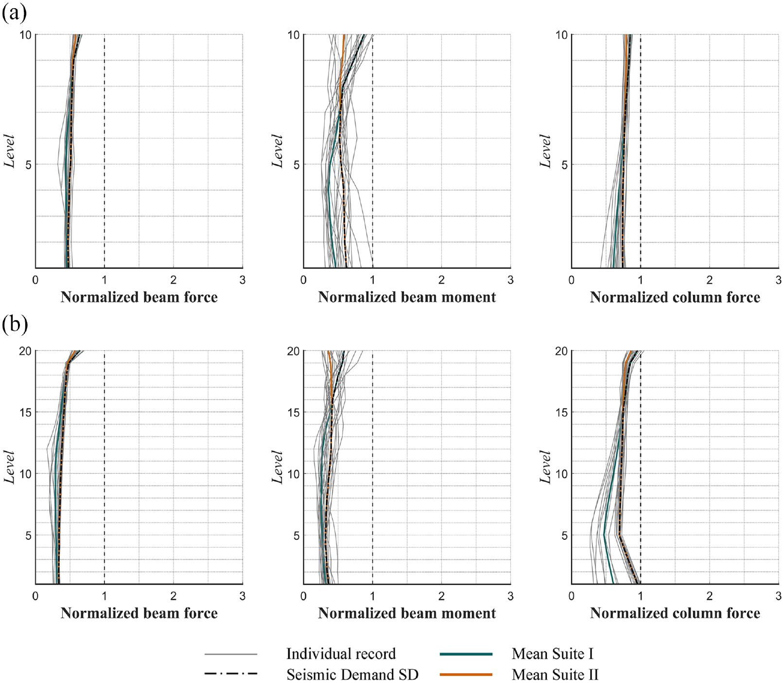
Force demand capacity ratios. (a) 10-story VE-BRBF. (b) 20-story BRBF.
The figure is structured using two rows representing the buildings (i.e. 10 and 20 stories) and three columns representing the SDs, namely, beam axial force, beam moment, and column axial force, organized from left to right, respectively.
The figure shows that the developed equations captured the seismic responses well with all calculated force-to-design-demand ratio below 1. Moreover, it illustrates an accumulated overdesign, particularly in column and beam axial forces, when descending from the top stories down. This overdesign stems from the low probability of BRBs achieving full strain hardening and yield simultaneously along the height of the buildings, as reported in previous studies (Richards, 2009; Shrestha and Bruneau, 2018). This overdesign highlights the adequacy of the under-sized column sections utilized in the first 4 stories of the 20-story frames. Furthermore, the assumption of not considering the velocity-related damping forces on the design axial beam forces is validated by the analysis results. Furthermore, the resulted overdesign can be quantified to reduce the tonnage of the proposed VE-BRBF system.
Conclusion
This article assessed the adequacy of the traditional approach of story design shear amplification on 10- and 20-story buckling-restrained steel braced frames through an inelastic stability coefficient versus the proposed approach of incorporating a source of post-elastic lateral story shear stiffness in mitigating P-delta effects embodied in dynamic instability and excessive drifting. The post-elastic story shear stiffness is implemented utilizing a novel system, the VE-BRBF, which integrates vertically aligned VE dampers in BRBFs with an inverted-V bracing configuration. The assessment involved NLRHA considering historical earthquake records representing the seismic profile of Vancouver, BC. deaggregated from the 2% in 50 years UHS, namely, crustal, in-slab, and subduction interface. The following conclusions are drawn:
The classic approach of amplifying the story design shear force demand using inelastic stability coefficient to mitigate P-delta effects adopted in the NBC (2020) and CSA S16:24 was found to be adequate in preventing global instability and excessive drifting under the crustal and in-slab earthquakes in BRBFs despite overlooking the imposed height limitation of 40 m. Contrarily, it was found to be insufficient under the subduction interface earthquakes, where seismic responses involved cases of global instability and excessive drifting.
Incorporating post-elastic lateral story shear stiffness of the negative stiffness of P-delta plus a 2.0% of the elastic lateral story shear stiffness maintained for a story drift ratio of at least 2.5% demonstrated sufficient in mitigating P-delta effects and imposing recentering mechanism resulting in repair-limit post-earthquake residual drifts regardless of the building height and the source of seismic excitation.
The proposed VE-BRBF demonstrated significant improvements over traditional BRBFs in terms of stable seismic performance and post-earthquake response, enabling rapid functional recovery and/or continued operation.
The proposed design equations effectively confined the seismic force demands of the VE-BRBF. However, an overdesign was observed in the beams and accumulatively in the columns, particularly when descending from the top stories. This overdesign led to a significant increase in member sizes, reaching 30% and 40% in the 10- and 20-story buildings, respectively, compared with conventionally designed counterparts. The overdesign primarily results from the low probability of BRBs achieving full strain hardening and yielding simultaneously across the building height while VE dampers develop their maximum forces. This is a common outcome associated with capacity-design-based equations, as noted in previous studies. Nevertheless, this overdesign can be quantified to reduce the tonnage of the proposed system.
Footnotes
Declaration of conflicting interests
The author(s) declared no potential conflicts of interest with respect to the research, authorship, and/or publication of this article.
Funding
The author(s) disclosed receipt of the following financial support for the research, authorship, and/or publication of this article: Financial support was provided by the Fonds de recherche du Québec—Nature et technologies (FRQNT) through Fellowship No. 313433.
Data Availability Statement
Strong ground-motion data used in this study were obtained from the PEER database (https://peer.berkeley.edu/), the Geotechnical Investigation Centre of El Salvador (CIG) database (www.marn.gob.sv), the K-NET database (www.k-net.bosai.go.jp), and the United States Geological Survey (USGS) database (![]() ).
).