
Abstract
This state-of-the-art review provides an overview of the evolution of self-centering structures from early historical structures that inherently exhibited a recentering response to modern systems engineered for enhanced seismic resilience. From the early research investigations that were conducted since the 1960s, to the sharp increase of interest in this topic over the last two decades, self-centering seismic-resistant structures that can mitigate both damage and residual drifts following major earthquakes have seen significant advances. These systems achieve the intended self-centering response by either allowing for the rocking of primary structural elements in a controlled manner, commonly coupled with mechanical restraints and energy dissipation devices, or by including self-centering devices as main structural or supplemental structural members. To better explain the concepts and the underlying mechanics governing their seismic response, detailed schematic illustrations were developed in this article, highlighting the fundamentals behind each of these systems. This article covers a historical overview, presents the state of the research and of the art, discusses general design challenges and practical considerations, and concludes with future research needs to advance the development and broader application of self-centering systems in real structures.
Introduction
Conventional earthquake-resistant design of structures typically relies on ductile details specifically selected to sustain substantial inelastic deformations and dissipate energy in a controlled manner, thus limiting the force demands elsewhere in the structure and protecting the integrity of its global load-carrying systems. While buildings designed in this manner may ensure an acceptable safety level by avoiding catastrophic failures under design-level earthquakes, they are susceptible to two major drawbacks: considerable cumulative damage in main structural elements and residual deformations, as illustrated in Figure 1a. Because damage is expected to accumulate in ductile elements, they will require repair or even replacement following a major earthquake event. The hysteretic behavior of these elements, especially when they are damaged, can result in significant residual deformations in a structure, which can impose challenges in post-earthquake rehabilitation, and even cause the total loss of a structure. These represent considerable costs associated with damage to structural and non-structural components, and the disruption of business operations. Moreover, the simultaneous extensive damage to a large number of structures, especially essential infrastructure systems and networks, can create significant obstacles to post-earthquake emergency response and result in a prolonged disruption of regional or even national economies.
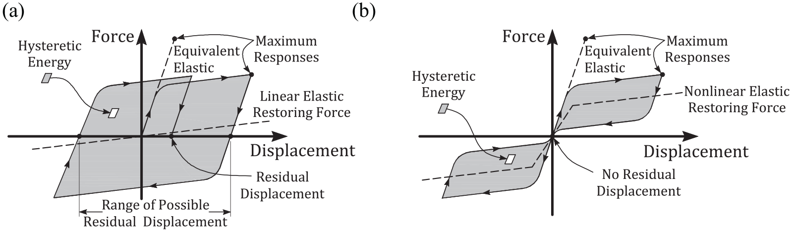
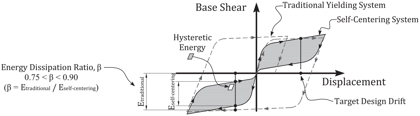
Characteristic behavior of (a) conventional seismic-resistant systems and (b) self-centering systems.
To reduce the social and economic disruptions caused by earthquakes, performance-based seismic design (PBSD) which combines life-cycle considerations with a set of performance objectives that are specific to each structure, are being increasingly used to achieve a more predictable performance in the event of an earthquake. A defining design parameter in PBSD is the acceptable level of building damage for a specified level of seismic hazard. While conventional damage-prone earthquake-resistant structures could prevent structural collapse and the loss of life in a major earthquake, these structures could still sustain extensive damage and residual deformations that lead to service disruptions, repair, and even demolition. To work towards more resilient and sustainable cities, research and development in PBSD have focused on designing structures to raise their seismic performance level while keeping construction costs reasonable. Many of these structures are designed to dissipate seismic energy using supplemental damping systems, or limit seismic energy transfer through isolation systems. The performance objectives, in these cases, aim to achieve minimum service disruption following major earthquakes, instead of only meeting life-safety requirements. Another promising approach to achieving this goal is through self-centering structural systems that exhibit the ability to return to their pre-excitation configurations after an earthquake. These structural systems typically exhibit a flag-shaped hysteretic response, as illustrated in Figure 1b. Although the hysteric energy dissipation of a self-centering system is typically less than that of a conventional system, the main advantage of the self-centering system is that it returns to its pre-excitation configuration at the end of an earthquake event with no residual displacement.
Over the past four decades, the development of self-centering structural systems has yielded a number of innovative systems that are economically viable alternatives to conventional earthquake-resistant designs. The development has, in turn, led to several successful implementations in regions of high seismicity. This article provides a broad overview of the history and recent advances in self-centering structural systems and is organized into the following major sections: (1) early historical self-centering systems; (2) self-centering rocking structures; (3) self-centering mechanical devices; and (4) challenges and research needs in the practical applications of rocking systems. General considerations for the seismic design of self-centering systems are also discussed. Detailed illustrations summarizing the development of self-centering structural system concepts in each category have been developed to better explain the fundamental mechanics behind each of the concepts that are reviewed, and to potentially inspire a broader application and further development of self-centering structural systems described in this work and beyond.
Early historical self-centering systems
The recorded history of self-centering structures goes as far back as the Bronze Age (3000–1000 BC), when ancient builders were designing structures mainly supported by free-standing columns in the ancient Egyptian and Minoan civilizations (Cline, 2010). Whereas the Egyptian civilization used stone columns, the Minoans constructed their columns from whole tree-trunks (Cline, 2010). Wooden columns were also widely used by the ancient Chinese civilization since the early 700s BC, where these columns were free-standing at their base and joined to the overhanging roof (Steinhardt, 2019). The ancient Persian empire also used free-standing, tall, and slender wooden columns to support their temples and palaces in the early stage, but constructions were eventually transitioned to using columns made of stone (Oleson, 2008). In ancient Greece, stone columns were used as the primary support for their temples in the late 500s BC, which evolved into three main column types: Doric, Ionic, and Corinthian (Barletta, 2001). As structures became larger in ancient Greece, the slenderness of the columns continued to increase, and some columns began to be constructed in multi-drums (Barletta, 2001). The ancient Romans later adopted the three types of Greek columns, but focused on constructing free-standing columns that were monolithic instead of using stacked drums (Oleson, 2008). Many ancient Indian temples constructed since 6 CE also consist of free-standing wooden or stone columns that were influenced by ancient Persian architecture (Boardman, 1998). Figure 2 provides examples of ancient free-standing columns and their approximate chronology.
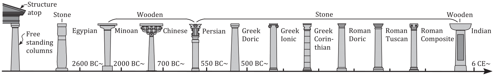
Ancient free-standing columns.
Although many of these ancient structures were partially or entirely destroyed by natural disasters or anthropogenic reasons, there is still a considerable number of them, primarily ancient Greek and Roman temples and ancient Chinese palaces and pagodas, that have survived natural disasters throughout the centuries, including hundreds of strong earthquakes (Steinhardt, 2019; Stiros, 2020). As illustrated in Figure 3a, these Greek and Roman temple columns were typically comprosed of free-standing monolithic or multi-drum marble columns supporting massive free-standing epistyles and the frieze atop. Ancient Chinese palaces and pagodas used a different building technique called dougong to connect the top of free-standing monolithic wooden columns with the mega overhanging roof and distribute the weight, as illustrated in Figure 3b. In these ancient structural systems, the self-weight of the free-standing columns and structure atop provides an appreciable amount of gravitational force to the columns, and generates moment resistance at the column ends, which in turn provides lateral resistance to the system. Under significant lateral loading, the response of these structures is composed primarily of rocking and sliding among the individual blocks of the structure (columns and the superstructure) and the ground, and dissipating energy through impact and friction. These inherent characteristics result in systems that minimize structural resonance during seismic responses and recenter after a major earthquake.
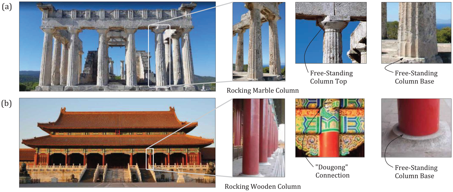
Ancient self-centering structures: (a) Greek temple and (b) Chinese palace.
Early modern interest in self-centering structures was mainly focused on rocking structures that resembled the response of the ancient self-centering structures. This interest can be traced back as early as when Milne (1885) studied the seismic overturning response of slender, free-standing blocks, which related the stability of free-standing blocks to their aspect ratio. In the early 1900s, Kirkpatrick (1927) identified two additional parameters that affected the seismic stability of free-standing blocks: the size of the block (i.e. the rotational moment of inertia of the block) and the predominant period of the ground motion. The size effect was later confirmed by Ikegami and Kishinouye (1947, 1950) following their field investigations after the Nankai earthquake and the Imaichi earthquake in Japan. Muto et al. (1960) showed that the dynamic response of a free-standing block was governed by its negative stiffness upon rocking initiation. These pioneering studies defined the basics of the dynamics of rocking structures. Still, it was Housner’s (1963) study that directed the attention of the earthquake engineering community to rocking structures, by defining the mechanics of rocking actions and the associated size–frequency scale effect, which, as he stipulated, enabled a number of tall, slender structures to survive the 1960 Chile earthquake, whereas some more stable-appearing, fixed-based structures were more severely damaged.
Following Housner’s work, Beck and Skinner (1974) extended the concept of rocking to enhance the seismic resistance of tall reinforced concrete (RC) bridges by allowing the bridge piers to uplift during a major earthquake. This concept was subsequently used in the design and construction of the South Rangitikei Railway Bridge in New Zealand in 1981, as shown in Figure 4a. This rocking railway bridge is 70 m tall and has an overall length of 315 m (Cormack, 1988). Torsional-beam dampers (Skinner et al., 1993) were installed between piers and their foundations to limit the amplitude and number of rocking cycles. The bridge’s weight, which enables its self-centering capability, is transmitted directly to the foundation through thin laminated rubber bearings without engaging the dampers.
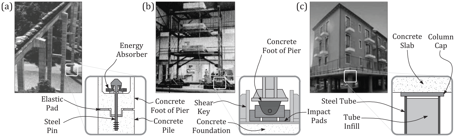
Early modern self-centering structures: (a) Rangitikei Railway Bridge in New Zealand;(b) rocking steel moment frame tests in the United States; and (c) residential buildings withkinematic supports in Russia.
Shortly after the conceptual design of the first rocking RC bridge, rocking was further extended to steel moment frames with a series of investigations conducted in the United States in the late 1970s. Clough and Huckelbridge (1977) performed preliminary experimental and analytical studies into the effects of column uplift in steel moment frames responding to seismic loading. A three-story single-bay steel frame, shown in Figure 4b, was studied both with and without column uplift. This rocking frame was pinned at the column bases to allow rigid body rotation upon column uplift, with impact pads placed below the column bases. Vertical roller bearings were installed to transfer shear at each column base with minimum uplift resistance. This study showed that column uplift significantly reduced the seismic demands on a steel moment frame when compared to the fixed base response of a similar structure. Subsequently, Kelly and Tsztoo (1977) added steel bars to the base of the same three-story steel rocking frame to dissipate energy when the column uplifted. The response of the rocking frame with energy dissipation devices showed improvements, which preliminarily established the effectiveness of combining rocking with energy dissipation devices for frame structures. These test results, along with similar analytical results obtained by Beck and Skinner (1974) and Meek (1975), led a study on a more complex structural system—an 8.5 m, nine-story three-bay steel moment-resisting frame (MRF; Huckelbridge, 1977). Results of this test further confirmed the feasibility and benefits of allowing column uplift in steel moment frames. In the same study, Huckelbridge (1977) also mentioned potential applications of the concept of rocking to RC frame structures, shear walls, and core-stiffened systems.
Around the same time, the Russian Construction State Committee focused research efforts on developing seismic isolation systems that were inexpensive while simple in construction (Eisenberg, 1976). These investigations led to the development of so-called kinematic supports, which are vertically placed cylinders replacing the entire bottom-story columns of structures, as shown in Figure 4c. These kinematic supports rock freely in response to earthquake excitations, effectively forming a “soft story” to limit the forces that are transferred to the superstructure resting above them, while having an inherent self-centering ability (Polyakov, 1974). Since then, a number of buildings have been constructed on kinematic supports in Russia and in other former Soviet Union countries.
By the early 1980s, more extensive research on self-centering systems started to develop into two main directions. One direction was based on the concept of rocking, where parts of structures are allowed to rock in response to severe seismic loading, either freely or in a controlled manner using a variety of mechanical restraints and energy dissipation devices. The other direction focused mainly on achieving the self-centering response of structural systems by using devices with self-centering properties either added to typical structural configurations or replacing main structural members. Figure 5 summarizes the self-centering systems according to their structural configurations, along with the corresponding number of studies that are referenced and discussed in the subsequent sections of this article.
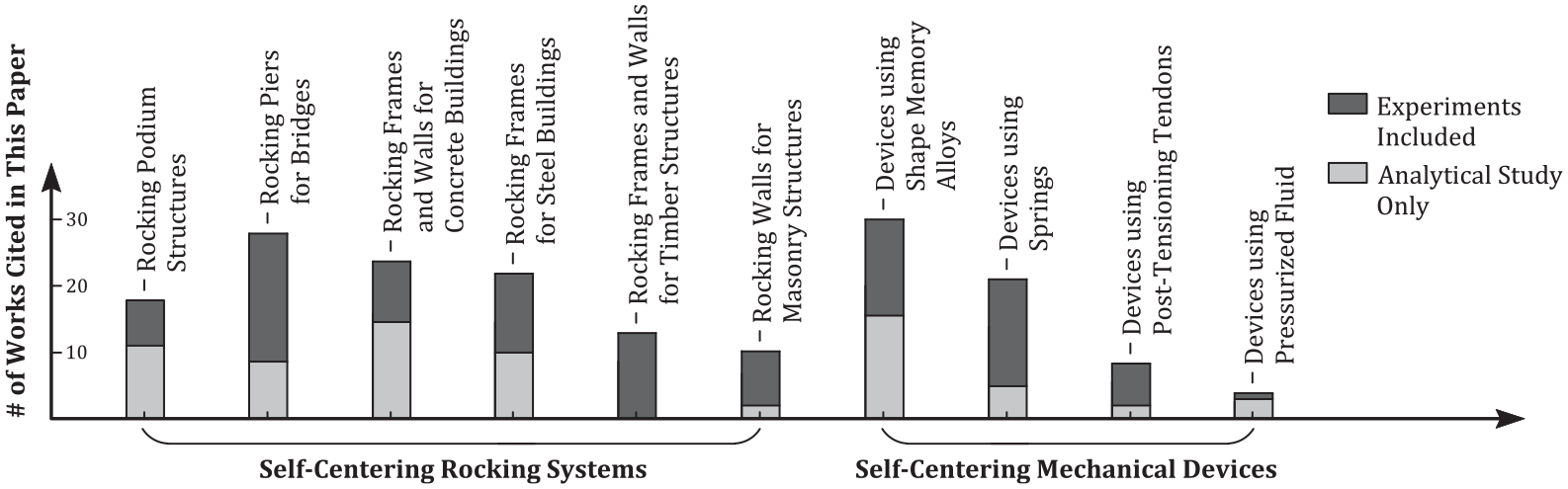
Summary of self-centering systems and the corresponding works cited in this Article.
Self-centering rocking systems
Rocking podium structures
The concept behind ancient free-standing temples was extended to a class of rocking structures that was first developed in Russia and former Soviet Union countries (Polyakov, 1974). In these structures, the columns of the entire bottom story were designed to rock during earthquake excitations to achieve seismic isolation of the superstructure above, while exhibiting a gravity-recentering ability. These structures are more commonly referred to as rocking podium structures, as shown in Figure 6. Implementation of rocking podium structures started in the early 1980s, mainly in the Siberian seismic regions of Russia, shortly after feasibility studies were conducted by the Russian Construction State Committee (Eisenberg, 1976). By the early 2000s, Russia and other former Soviet Union countries had constructed more than 400 rocking podium structures (Cherepinskiy, 2004). The self-centering capabilities of these structures remained undeteriorated over the years even following a considerable number of earthquakes (Uzdin et al., 2009). In addition, the practical implementation of rocking podium systems made it possible to assess their performance in actual buildings. Field vibration tests (Semenov and Kurzanov, 2011; Uzdin et al., 2009) and free-rocking tests (Semenov, 2015; Semenov and Kurzanov, 2011) were conducted at several sites in Russia, providing full-scale experimental data on the dynamic behavior of rocking podium structures. These tested structures consisted of rocking columns that are either steel cylinders or RC columns capped with steel plates to avoid concrete crushing upon rocking. The columns were specifically sized to allow uplift, sustain rocking motion, and limit force transfer to the superstructure, without overturning under a design-basis earthquake. In recent years, research interest in the study of rocking podium structures has noticeably increased. Several studies were devoted to understanding the dynamics of free-standing rocking columns and podiums (Drosos and Anastasopoulos, 2014, 2015; Makris, 2014; Makris and Vassiliou, 2013; Mouzakis et al., 2002; Papaloizou and Komodromos, 2009; Vassiliou et al., 2021). Meanwhile, an increased number of researchers started to focus on the design and practical application of more controllable rocking columns and podium structures. Dimitrakopoulos and DeJong (2012) investigated the damped and undamped responses of a rocking column with a central tendon under pulse-type excitations. Vassiliou and Makris (2015) studied the dynamics of vertically restrained rocking columns using post-tensioning (PT) to control the post-rocking stiffness and suppress the dynamic response under long-period excitations. Makris and Aghagholizadeh (2019) studied the dynamic response of free-standing columns coupled with supplemental hysteretic and viscous dampers. Ríos-García and Benavent-Climent (2020) proposed a rocking column with dampers to dissipate energy and a “gapped” steel bar at the center to control the negative stiffness range. These systems control the rocking response with mechanical restraints and energy dissipation devices, rather than relying solely on the free-rocking response of the rocking columns.
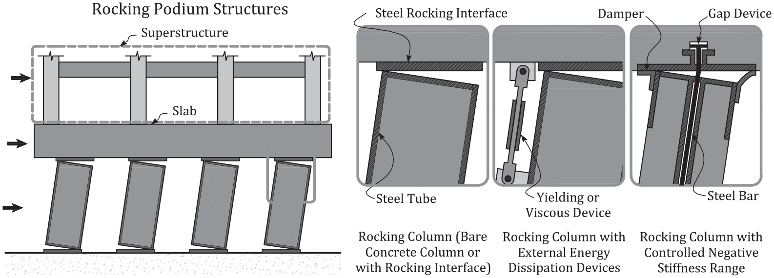
Rocking podium structures.
Rocking piers for bridge structures
Following the early applications of rocking piers in the Rangitikei river bridge in New Zealand (Beck and Skinner, 1974), several rocking configurations were proposed for bridge structures, as shown in Figure 7. Priestley et al. (1978) presented pure rocking of bridge piers on their foundation and carried our preliminary shake table tests on the system. Mander and Cheng (1997) proposed to use unbonded PT tendons to enhance the lateral strength of rocking piers. They also suggested the use of steel–steel rocking interfaces to protect the rocking pier from damaging under impact actions. Similar systems for precast segmental or monolithic rocking piers were investigated both analytically and experimentally (Cai et al., 2018; Chou and Chen, 2006; Dawood et al., 2012; ElGawady and Dawood, 2012; Guerrini et al., 2015; Hewes and Priestley, 2002; Hung et al., 2011; Ichikawa et al., 2016; Kwan and Billington, 2003; Palermo et al., 2007; among others). To avoid local concrete damage in the rocking region, researchers have proposed the use of high-strength concrete (Billington and Yoon, 2004; Ichikawa et al., 2016; Motaref et al., 2014; Nikoukalam and Sideris, 2017; among others), proper confinement with steel jacketing (Chou and Chen, 2006; White and Palermo, 2016) and fiber-reinforced polymer jacketing (Chou and Chen, 2006; ElGawady and Dawood, 2012; Hewes and Priestley, 2002), polyurethane end segments (Nikoukalam and Sideris, 2017), and rubber layers between rocking interface (Kashani et al., 2018). The concept of combining rocking and supplemental energy dissipation devices has also been extended to rocking bridge piers to improve their energy-dissipation capabilities and reduce displacement demands. Proposed configurations of energy dissipation devices include internally placed steel yielding bars or shape memory alloys across the rocking interfaces (Cai et al., 2018; Motaref et al., 2014; Ou et al., 2007, 2010; Palermo et al., 2007; Wang et al., 2008; among others) or externally connected replaceable yielding elements (Chou and Chen, 2006; Guerrini et al., 2015; Nikoukalam and Sideris, 2017; White and Palermo, 2016; Xu et al., 2019; among others) or viscous elements (Pollino and Bruneau, 2010). Self-centering base isolation systems were also proposed for use in bridge structures (Bhuiyan and Alam, 2013; Mishra et al., 2016; Ozbulut and Hurlebaus, 2010; among others).
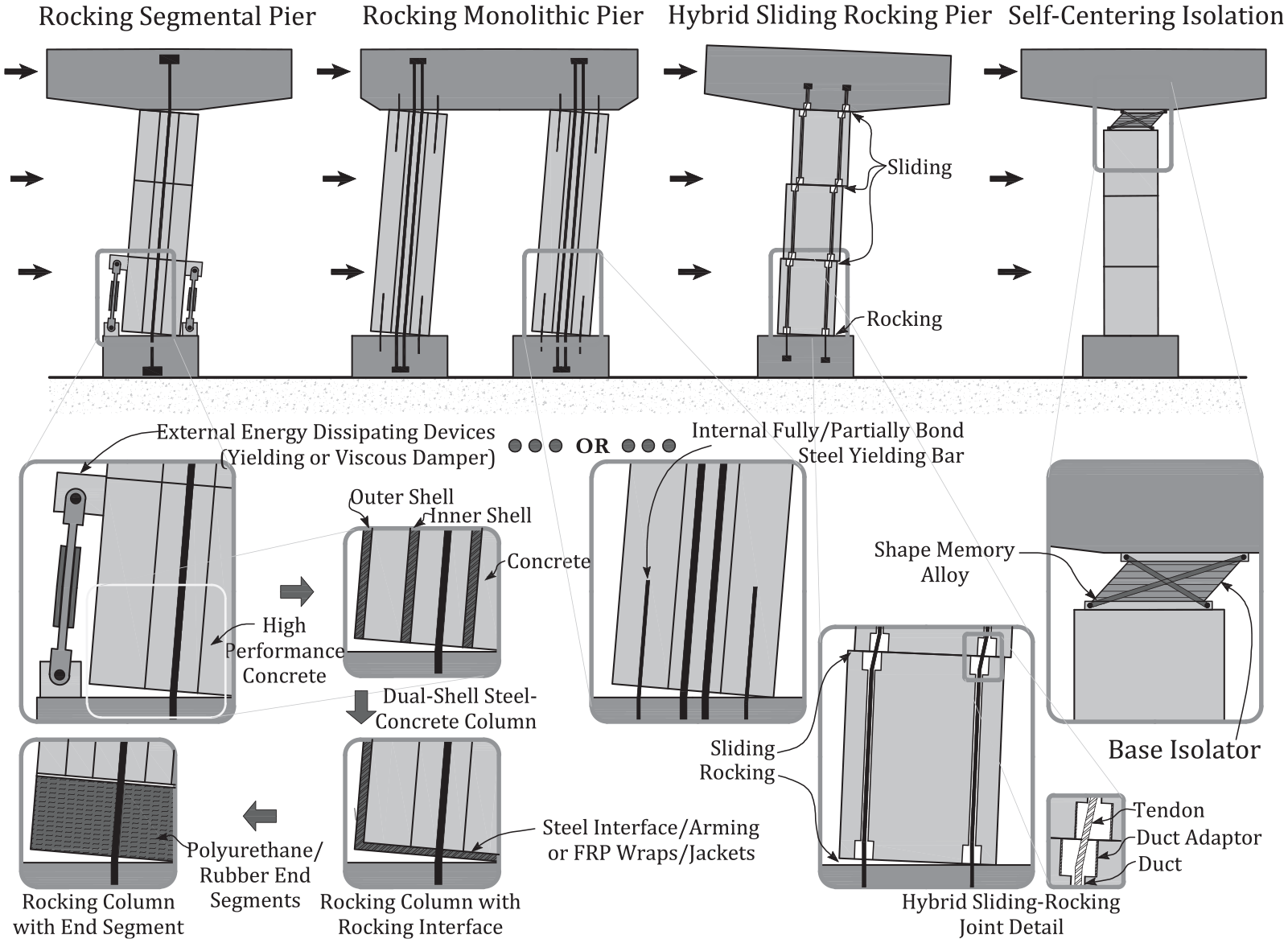
Rocking piers for bridge structures.
In the above precast concrete segmental rocking pier systems, adequate shear resistance is typically provided against joint sliding. An alternative concept was proposed by Sideris et al. (2014b), termed the hybrid sliding-rocking system, which consisted of segmental girders with unbonded PT tendons and rocking joints, and segmental piers with end rocking joints and intermediate sliding joints connected through internal unbonded PT tendons. The rocking joints were designed to provide high self-centering capacity with low-energy dissipation, while the sliding joints provided more considerable energy dissipation through friction sliding actions with additional recentering actions. Results of shake table tests on a large-scale bridge specimen validated the use of this hybrid sliding–rocking concept to enhance the seismic performance of bridges (Sideris et al., 2014a, 2015). Design objectives and equations were also elaborated for this concept based on quasi-static lateral cyclic tests at large drift ratios (Salehi et al., 2021; Sideris et al., 2014b) and numerical studies (Salehi et al., 2017).
Rocking frames and walls for concrete buildings
Research on rocking precast concrete buildings under the PRESSS (PREcast Seismic Structural Systems) program in the United States marked a notable step in the development of self-centering building applications (Priestley, 1991). The program aimed to develop innovative precast concrete seismic-resistant systems that would be more viable alternatives to the emulative systems that were being used to achieve performance similar to conventional cast-in-place monolithic systems (Ericson and Warnes, 1990). Connections of precast systems were typically designed either as elastic elements to induce flexural yielding within the precast members at dedicated locations, or as ductile elements to form plastic hinges within the connections. However, considering the difficulty and expense in the detailing and post-earthquake repair of these emulative systems, the PRESS program proposed precast connection concepts that relied on a controlled rocking response at the ends of the precast members in the joint region, to accommodate the inelastic demands on the systems. In addition, these rocking precast connection concepts were the first to utilize unbonded PT steel to increase their lateral load and displacement capacities. The controlled rocking motions at the joint interface significantly reduced tensile demands in the precast members. At the same time, the PT provided an additional restoring force that facilitated recentering of the structure, even under relatively large lateral displacements. Based on the concept of controlled rocking with PT steel, several rocking concrete systems were developed that mitigate both damage and residual deformations under major earthquakes, while having a comparable or even improved lateral displacement capacity when compared to their conventional counterparts.
Priestley and Tao (1993) were the first to investigate, through numerical studies, the feasibility and efficiency of connecting precast concrete beam and column elements using unbonded PT steel and allowing rocking at the beam–column interface. Priestley and MacRae (1994) then experimentally validated the idea through quasi-static tests on interior beam–column joint subassemblies. These systems relied only on unbonded PT to provide recentering forces and therefore exhibited a bilinear elastic hysteretic behavior with low levels of energy dissipation. To improve the energy dissipation capability, Stanton et al. (1993) proposed a hybrid system where self-centering and energy dissipation properties were coupled through the combination of unbonded PT tendons and longitudinal steel bars or external energy dissipation devices. Since then, the concept of post-tensioned RC frame systems has been further refined to improve constructability and to enhance performance (Buddika and Wijeyewickrema, 2016; Erkmen and Schultz, 2009; Guo et al., 2017; Morgen and Kurama, 2008; Pampanin, 2005; Perez et al., 2013; among others). Proposed refinements include the use of cable-stayed and suspended solutions that simplifies and expedites the construction sequence. Other improvements include the use of draped tendons or cables to optimize the system’s response to combined gravity and lateral loads effects, the use of external supplemental damping devices including hysteretic systems or systems making use of advanced materials, such as shape memory alloys (SMAs) or visco-elastic dampers and finally improvements on the shear transfer mechanism through the development of special shear keys.
The post-tensioned rocking concept was also adapted to precast concrete shear wall systems. In these systems, shear wall panels were split either horizontally (Priestley et al., 1996; Stanton et al., 1993) or vertically (Kurama et al., 1999) to allow individual panels to rock about their respective bases. The recentering action of these systems was mainly enabled by their self-weight, and supplemented by unbonded PT tendons anchoring the wall panels to the foundation. Supplemental energy dissipation was also included in these systems by adding viscous-fluid dampers as braces placed diagonally in the wall plane (Kurama, 2000). Others proposed to distribute friction devices (Guo et al., 2014) or yielding devices across the rocking joints, such as regular or dog-bone-shaped mild steel bars (Kurama, 2002; Restrepo and Rahman, 2007) and U- or O-shaped steel yielding connectors (Sritharan et al., 2015; Stanton, 2003). In the same manner, the concept of rocking was extended to RC cantilever wall systems. Holden et al., (2003) proposed a rocking cantilever wall system prestressed with unbonded tendons while dissipating energy through yielding of conventional reinforcement. Rocking RC-coupled shear walls were proposed by Kurama and Shen (2004), which allowed for the rocking of coupling beams and walls that were post-tensioned together and to the foundation. Studies on these systems demonstrated stable lateral resistance with low structural damage and with limited residual deformations, even under large lateral displacements. Furthermore, replaceable components were introduced in the rocking region to prevent concrete spalling and crushing under high local compressive stresses induced by rocking actions. Examples of replaceable components include steel jackets covering concrete rocking toes (Guo et al., 2014) and disc spring devices replacing concrete rocking toes (Xu et al., 2018a). An overview of the different types of rocking frames and walls for concrete structures is schematically illustrated in Figure 8.
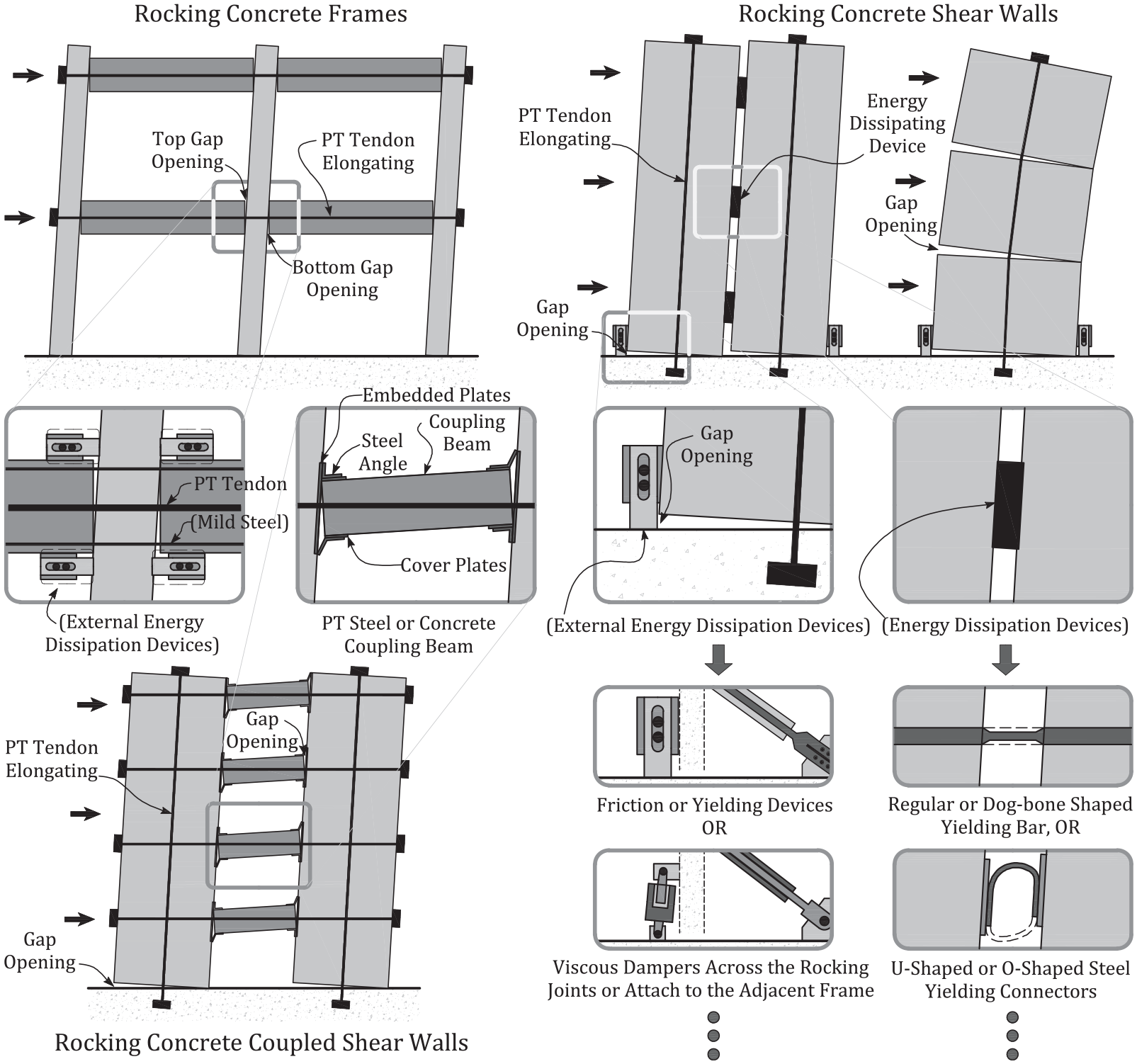
Rocking frames and walls for concrete buildings.
Rocking frames for steel buildings
Following the success of the PRESSS program in precast concrete rocking systems, research on controlled rocking systems extended into steel systems, as illustrated in Figure 9. Rocking steel MRFs were first proposed by Ricles et al. (2001) and Christopoulos et al. (2002b). Ricles et al. (2001) developed a PT connection for MRFs, which consisted of high-strength steel strands alongside the beam web and anchored to the exterior column flange. Steel angles bolted to both columns and beams were designed to dissipate energy by yielding under rocking actions, while the rest of the structure remaining elastic. The post-tensioned energy-dissipating (PTED) connection by Christopoulos et al. (2002b) provided recentering forces using high-strength PT tendons installed at mid-depth of the beams. Buckling restrained energy-dissipating (ED) bars were installed across the rocking interface to yield under rocking actions and dissipate energy. Subsequent experimental studies by Christopoulos et al. (2002b) on a PTED steel frame subassembly demonstrated its capability to undergo large inelastic deformations without damage and residual drift. This was further confirmed with seismic shake table tests on a three-story, two-bay, PTED steel frame designed and tested by Wang and Filiatrault (2008). An alternative PTED connection was also proposed by replacing the ED bars with friction devices (Kim and Christopoulos, 2008; Rojas et al., 2005). Cyclic tests on these friction-damped PTED connections showed stable and predictable behavior with good energy dissipation characteristics (Kim and Christopoulos, 2008).
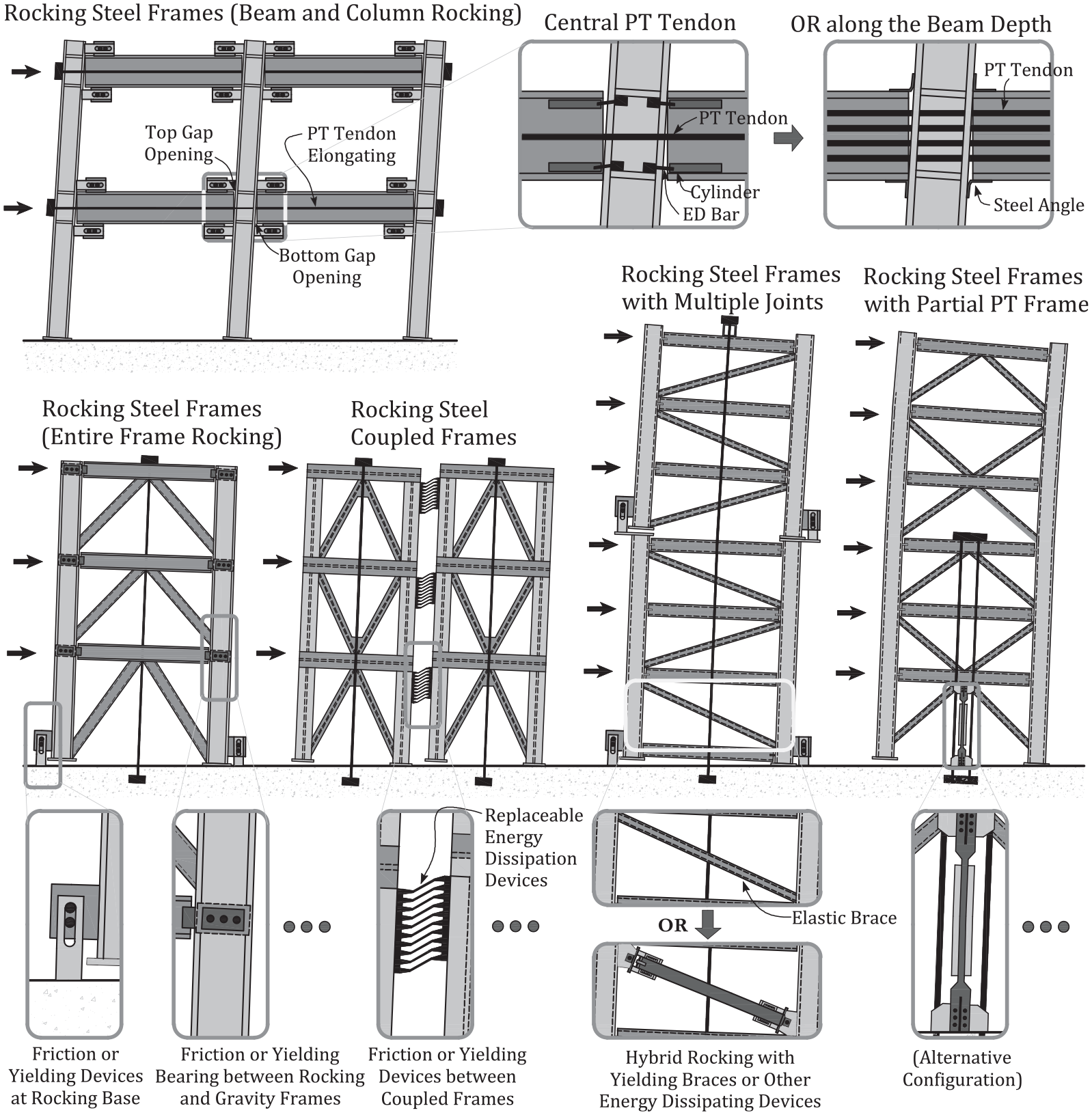
Rocking frames for steel buildings.
The rocking of entire steel frames with and without PT was also studied. Wada et al. (2001, 2009) proposed a truss-column structure with column splices yielding under tension while allowing separation of column segments. Midorikawa et al. (2002, 2003, 2006, 2008) performed numerical studies and shake table tests on MRFs and concentrically braced frames (CBFs) with base plates designed to yield and uplift. Tremblay et al. (2008b) tested a 50% scale two-story rocking steel CBF with viscous dampers at the column bases. The first controlled rocking steel frames with PT were investigated by Roke (2010), who tested chevron-braced frames with PT over the entire structure height, conceptually similar to post-tensioned rocking precast concrete walls that were discussed previously. Sause et al. (2010) performed hybrid simulation tests on a four-story controlled rocking CBF where friction-bearing dampers were used to dissipate energy and transfer lateral loads from gravity columns to the rocking frame. Replaceable yielding devices were first introduced to controlled rocking steel systems in the form of replaceable steel plates with butterfly cut-outs, followed by a series of experimental and numerical studies to validate this concept (Deierlein et al., 2011; Eatherton and Hajjar, 2014; Eatherton et al., 2014a; Ma et al., 2011). Wiebe et al. (2013a, 2013b) conducted shake table tests on a 30% scale eight-story controlled rocking CBF with four configurations, consisting of a combination of ED mechanisms with one or two rocking joints along the height, and with a conventional or self-centering energy dissipative (SCED) brace on the first story. Binder and Christopoulos (2018) proposed a concept to allow buckling-restrained braced frames to partially rock on their foundations as a cost-effective way to improve their seismic performance and limit excessive yielding of the braces. The concept of rocking was also extended to the seismic retrofit of conventional steel buildings by either installing additional rocking frames on the exterior of the existing structure (Pollino et al., 2017) or modifying the base of existing structures to allow for rocking (Mottier et al., 2018, 2021).
Rocking frames and walls for timber structures
The concept of post-tensioned rocking frames and walls originally developed for precast concrete structures was also extended to multi-story timber structures to improve their seismic performance, as illustrated in Figure 10. Newcombe et al. (2008) proposed a rocking timber frame concept based on refinement and adaptation of jointed ductile connections with PT steel. The beam-to-column connections were composed of laminated veneer lumber post-tensioned through unbonded tendons, and external or internal energy dissipaters. This concept was then extensively tested at a subassembly level by Iqbal et al. (2016). Di Cesare et al. (2017) developed a similar idea using long, prefabricated laminated timber connected by PT steel tendons or bars. Subsequently, Di Cesare et al. (2020) experimentally confirmed the seismic performance of a three-dimensional, three-story timber building designed using a combination of rocking timber beam–column joints and replaceable hysteretic dampers. Rocking timber wall panels that resembled post-tensioned rocking concrete walls were also proposed and experimentally studied (Ganey et al., 2017; Moroder et al., 2018; Newcombe et al., 2008; Sarti et al., 2016; among others). Bahman et al. (2017) applied cross-laminated timber rocking panels in the retrofit of soft-story wood-frame buildings and validated the concept through full-scale shake table tests. Pei et al. (2019) conducted full-scale shake table testing of a mass-timber building with post-tensioned timber rocking walls and observed no residual deformations or structural damage in the proposed system. Instead of relying on PT, Loo et al. (2014) introduced rocking in traditional wood shear walls through slip friction connectors replacing steel bracket hold-downs, and Hashemi et al. (2018b) expanded on this concept by introducing a self-centering mechanism into the slip-friction connector. More recently, Cui et al. (2020) and Li et al. (2021) introduced rocking in steel–timber hybrid shear wall systems to improve the seismic performance of multistory timber-based hybrid building structures.
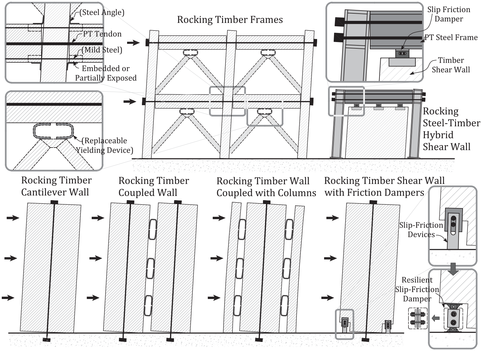
Rocking frames and walls for timber structures.
Rocking walls for masonry structures
Unbonded PT was initially applied to masonry structures, such as retaining walls, veneer walls, and bridge decks to improve their out-of-plane behavior. Laursen and Ingham (2001) investigated the cyclic in-plane response of unbonded post-tensioned masonry walls. They found that the in-plane cyclic loading would typically cause horizontal cracking at the base of the wall, resulting in a rocking-dominated post-cracking response. Similar behavior was obtained from quasi-static cyclic tests (Rosenboom and Kowalsky, 2004) and shake table tests (Wight et al., 2006), which validated the use of post-tensioned masonry wall systems for residential construction in New Zealand (Wight et al., 2007). The use of unbonded PT in improving the in-plane rocking behavior of masonry walls was also experimentally studied (Hassanli et al., 2016; Niu and Zhang, 2017), while others proposed to use external PT tendons to retrofit existing masonry walls (Ma et al., 2012, Liu et al., 2016). A comprehensive review of the seismic response of RC masonry shear walls can be found in a review paper by El-Dakhakhni and Ashour (2017).
Toranzo et al. (2009) investigated a different approach by adopting the concept of rocking to conventional masonry walls for use in conjunction with traditional masonry construction methods, recognizing the seismic vulnerability of conventional masonry buildings, especially in less-developed regions. The proposed rocking confined masonry walls relied solely on their self-weight to provide recentering forces and were coupled with low-cost external hysteretic energy dissipation devices designed to yield in flexure under rocking actions, while restraining the potential lateral sliding of the wall. In addition, steel plates were used to protect the rocking interface from crushing. Shake table tests of a 40% scale three-story confined brick masonry system confirmed the seismic performance of the system, with no observed residual deformation or discernible damage, and the hysteretic devices effectively reduced the lateral displacement demands (Toranzo et al., 2009). A schematic overview shown in Figure 11 summarizes the different types of rocking masonry wall systems mentioned in this section.
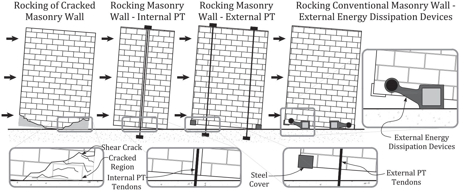
Rocking frames and walls for masonry structures.
Self-centering mechanical devices
Self-centering devices using SMAs
SMAs (Funakubo, 1984) are a class of materials that exhibit an inherent self-centering capability with appreciable hysteretic energy dissipation capacity. SMAs are however sensitive to fatigue that tends to deteriorate the self-centering capability of SMAs into a classical plastic behavior with residual strains after a large number of loading cycles. Aiken et al. (1992) and Witting and Cozzarelli (1992) were among the first to experimentally investigate the use of SMAs as an ED element in the form of wires (Aiken et al., 1992) and torsional bar components (Witting and Cozzarelli, 1992) incorporated at ends of diagonal braces. Desroches et al. (2004) tested the cyclic superelastic behavior of SMAs in both wire and bar configurations and confirmed their potential for seismic applications. SMA wires and bars were then used to develop various types of self-centering seismic dampers (Alipour et al., 2017; Bhowmick and Mishra, 2016; Qian et al., 2013, 2016; Zhang and Zhu, 2007) and braces (Kari et al., 2019; Koetaka et al., 2014; Miller et al., 2012; Zhu and Zhang, 2008; among others). Beam–column connections incorporating SMA rods were also developed for steel (Chowdhury et al., 2019; Ocel et al., 2004) and RC frames (Navarro-Gómez and Bonet, 2019; Youssef et al., 2008). Other researchers investigated the use of SMAs for RC buildings (Mas et al., 2017; Michels et al., 2018; Rius et al., 2019; Wang and Zhu, 2018; among others). The use of SMAs was also investigated in recent years to improve the seismic response of bridge structures (Billah and Alam, 2016a, 2016b; Mao et al., 2020; Varela, 2016; among others). Different types of self-centering seismic isolation devices incorporating SMAs have also been proposed (Attanasi et al., 2009; Cao et al., 2020; De Domenico et al., 2020; Gur et al., 2017; Jalali et al., 2011; Mishra et al., 2016; Ozbulut and Hurlebaus, 2010; Pang et al., 2021; among others). Figure 12 illustrates some typical seismic applications using SMAs. A more comprehensive review on this topic can be found in the work of Zareie et al. (2020).
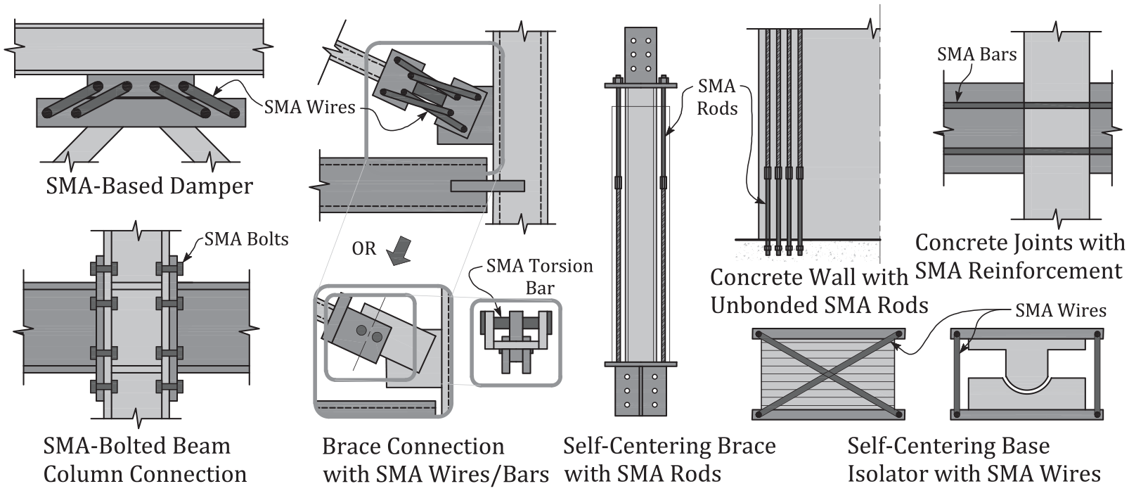
Self-centering devices using SMAs.
Self-centering devices using springs
As a simpler and less expensive alternative to SMAs, mechanical springs have been used in a number of devices to achieve self-centering response, as illustrated in Figure 13. One such device is the energy-dissipating restrain (EDR) that dissipates energy through a sliding friction mechanism using steel compression wedges and exhibits self-centering response through the recentering forces provided by an internal spring (Nims et al., 1993). The seismic performance of the EDR was experimentally investigated by Aiken et al. (1993) using the same small-scale three-story steel frame used for the SMA damper tests (Aiken et al., 1992), to allow for a direct comparison between EDRs and SMAs. Similar damper configurations combining disc springs with friction plates (Xu et al., 2016) or fluid dampers (Xu et al., 2018b) were also proposed. Springs were also used in some flat sliding base isolation systems to equip them with a self-centering capability (Chakraborty et al., 2016; Sachdeva et al., 2018).
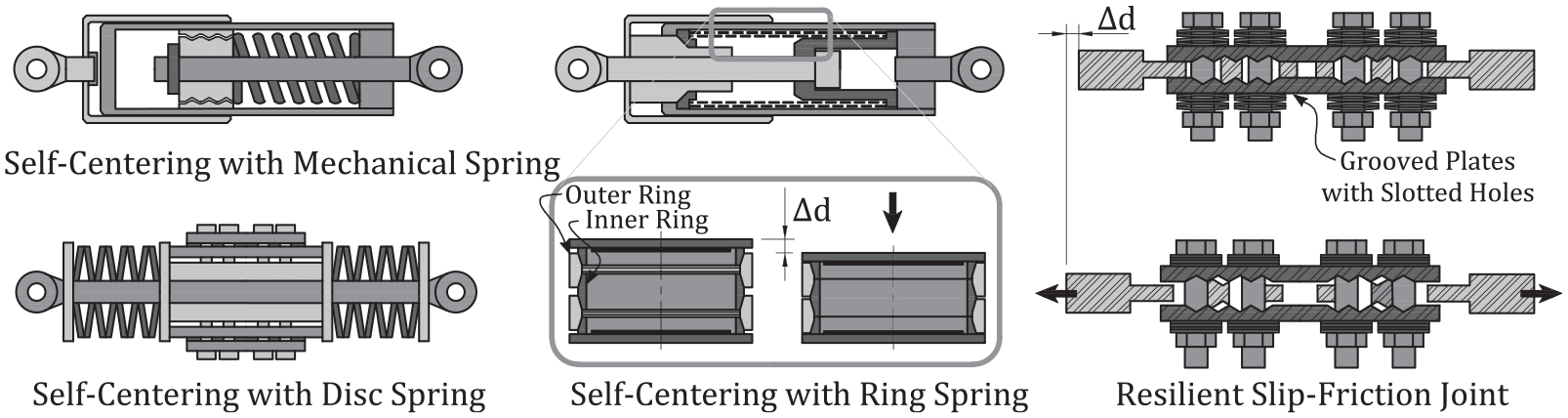
Self-centering devices using springs.
Kar et al. (1996) investigated the use of a special ring spring assembly as a self-centering component in ED devices. A typical ring-spring assembly consists of outer and inner rings that have tapered mating surfaces. The axial displacement of the assembly is accompanied by sliding between the rings on the grooved conical friction surface for energy dissipation, while the restraining effect of the outer rings creates circumferential compressive forces acting onto the grooved surface to recenter the assembly. The seismic performance of ring-spring dampers was first experimentally evaluated by Filiatrault et al. (2000), which was followed by research on the use of self-centering ring-springs in seismic dampers (Bishay-Girges and Carr, 2014; Fang et al., 2016, 2019; Zhu et al., 2020), bracing systems (Issa and Alam, 2019), and beam-to-column joints (Fang et al., 2018; Khoo et al., 2012).
Based on similar recentering mechanisms as the ring-spring, Zarnani and Quenneville (2015) developed a slip friction joint (SFJ) to provide self-centering and energy dissipation in a compact device. The SFJ consists of specially shaped grooved plates with slotted holes, clamped together through prestressed rods and disc springs. A series of subsequent studies on the resilient slip friction joint (RSFJ) showed its potential to be incorporated into various structural configurations, including shear walls (Hashemi et al., 2017, 2018b), MRFs (Hashemi et al., 2018a), and braced frames (Bagheri et al., 2020; Yousef-beik et al., 2020).
Self-centering devices using PT tendons
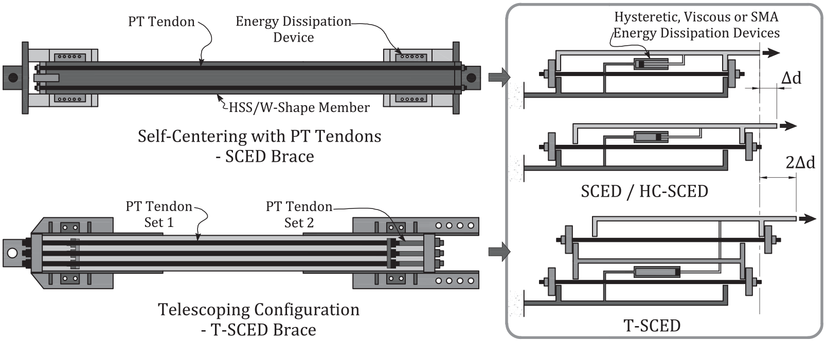
Mechanical devices using PT tendons as alternatives to achieve self-centering response have also been developed, as illustrated in Figure 14. Such devices were proposed by Christopoulos et al. (2008) and termed the SCED bracing system. The SCED system incorporates two bracing components post-tensioned together through a mechanism that ensures that the tendons are loaded in tension independent of whether the bracing system is loaded in tension or in compression, and coupled with ED elements to produce a self-centering bracing device with a flag-shaped hysteretic response. Quasi-static and dynamic seismic tests of full-scale brace assemblies and frame systems confirmed the expected self-centering behavior of the SCED bracing system (Christopoulos et al., 2008; Erochko et al., 2013; Tremblay et al., 2008a). Erochko et al. (2015a, 2015b) extended the SCED bracing concept by proposing: (1) a high-capacity self-centering energy-dissipative (HC-SCED) bracing system with a welded I-shaped inner member to transfer loads and (2) a telescoping self-centering energy-dissipative (T-SCED) bracing system with an additional moving element inside. The former achieved an enhanced force capacity, while the latter enabled an improved displacement capacity (Erochko et al., 2015a, 2015b). Zhou et al. (2014) and Chou and Chen (2015) proposed variations of dual-core self-centering brace systems with a deformation mechanism similar to the T-SCED concept but instead using buckling-restrained brace cores and PT fiber-reinforced polymer tendons. Others have proposed self-centering tension-only braces consisting of PT tendons for recentering, friction devices for dissipating energy, and high-strength steel cables to form the bracing assembly (Chi et al., 2018).
Self-centering devices using PT tendons.
Self-centering devices using pressurized fluid
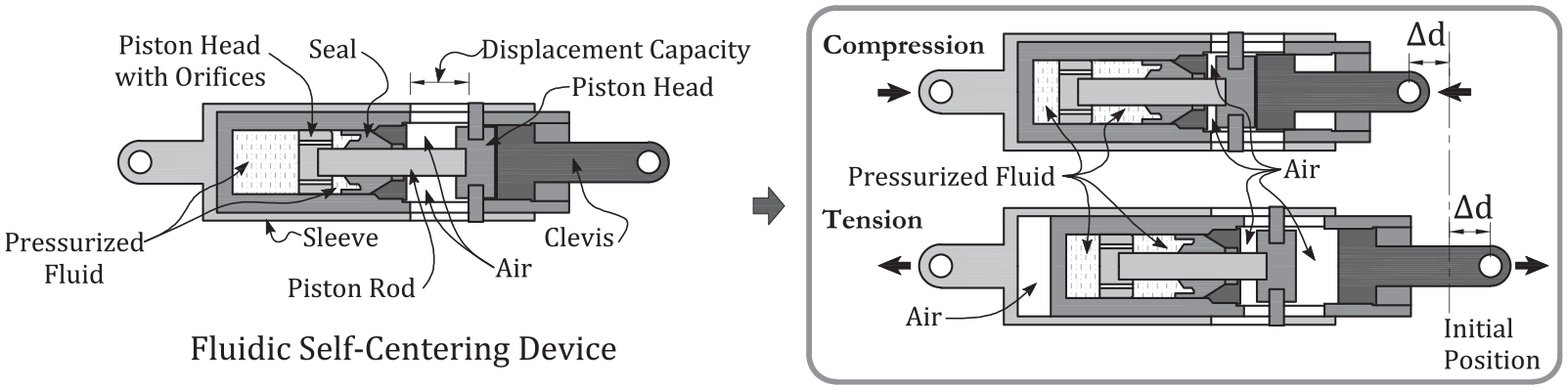
Fluidic self-centering devices (shown in Figure 15), utilize pressurized fluid to provide the restoring forces necessary to achieve a self-centering mechanism similar to that of a spring- or tendon-based self-centering device. Fluidic self-centering devices are similar to conventional fluid viscous dampers, but are designed in a way that the pressurized fluid always results in a preload that tends to recenter the device to its initial configuration, irrespective of the direction of the loading (Kitayama and Constantinou, 2016a). This technology has been widely applied in the military for the past four decades, and was first introduced to seismic-resistant structures by Tsopelas and Constantinou (1994) to be used in combination with a base isolation system to achieve precise self-centering capabilities. Kitayama and Constantinou (2016a) applied the fluidic self-centering devices in the design of seismic-resistant buildings and developed design and analysis procedures. Subsequent studies on the behavior of fluidic self-centering devices and numerical analyses of buildings equipped with such devices confirmed their potential for improving collapse resistance and minimizing residual drifts of buildings subjected to earthquake excitations (Kitayama and Constantinou, 2016b, 2017).
Self-centering devices using pressurized fluid.
Challenges and research needs in the practical application of self-centering systems
Self-centering structural systems have evolved over the past four decades through extensive analytical and experimental research. Figure 16 summarizes the available experimental studies on self-centering systems that are discussed in this review, grouped by structural configurations and types of experiments, with key observations highlighted. These studies have shown promising results confirming their ability to allow structures to sustain little or no structural damage even following severe earthquake excitations. However, a number of challenges have also been identified related to the practical implementation of self-centering structural systems, especially for self-centering rocking systems. In contrast to self-centering mechanical devices that can be directly integrated into conventional structural systems, most rocking systems utilize kinematic elastic gap-opening mechanisms that may introduce local discontinuities between the rocking systems and the rest of the structure, as shown in Figure 17a, and hence, imposing challenges in the design of connections. In addition, although base rocking systems are intended to control seismic demands by limiting the overturning moments at their base, higher mode effects, especially under strong ground excitations, can amplify the seismic demands, reducing the viability and effectiveness of these systems, as illustrated in Figure 18a. Furthermore, cost–benefit efficiency of self-centering systems in some cases can also impose challenges in promoting a wider implementation. These challenges, along with some potential solutions and future research needs, are discussed in the following sections.
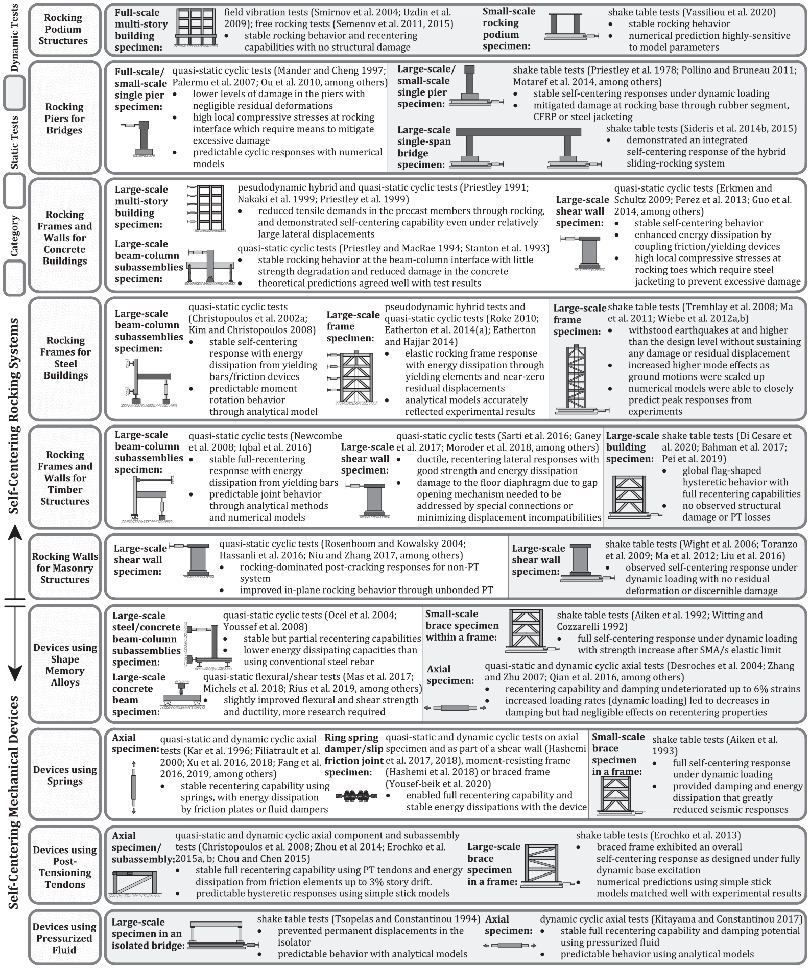
Summary of experimental studies on self-centering structural systems.
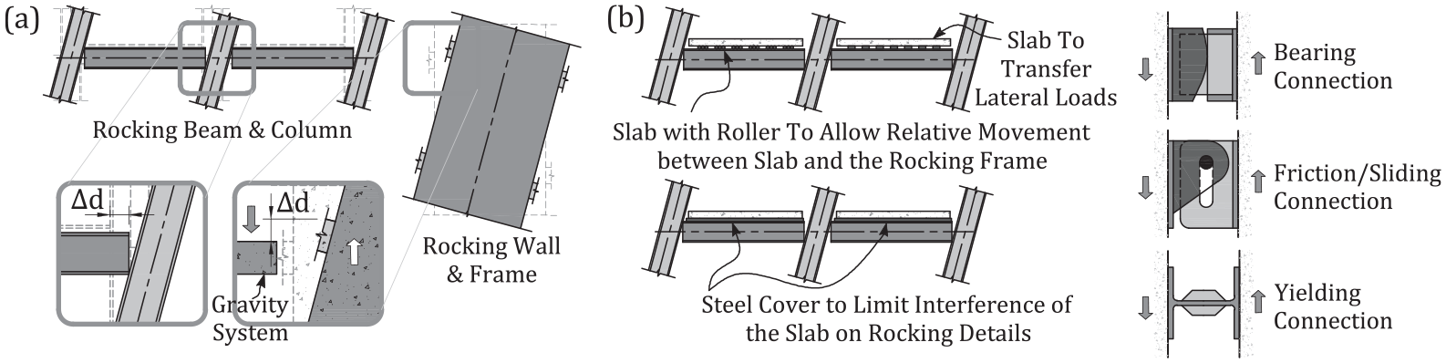
(a) Local discontinuities due to rocking actions and (b) floor diaphragm connections.
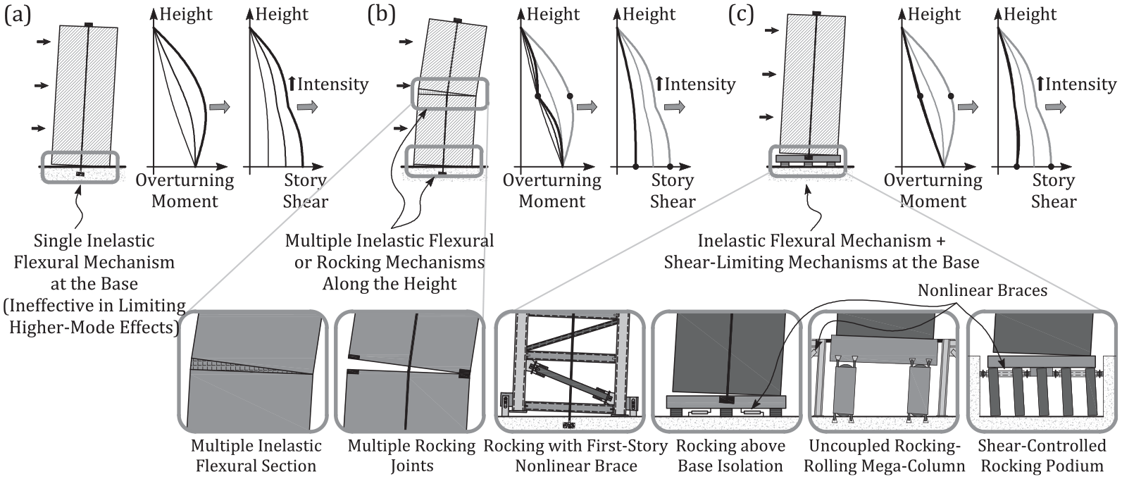
Higher mode effects and mitigation strategies.
Floor diaphragm connections in self-centering rocking systems
For self-centering MRF structures, the elastic gap-opening mechanism at the interface between the beams and the columns induces a relatively large expansion in the bay width of the frame. A conventional floor diaphragm would restrain such an expansion, thus affecting the behavior of the frame while imposing damage to the diaphragm. As such, this frame expansion needs to be accommodated by the floor diaphragm system and the connections that transfer lateral forces. A number of diaphragm and connection details have been proposed to address this frame expansion issue, as illustrated in Figure 17b. Garlock et al. (2007) proposed to restrain floor diaphragms only at certain beams per floor to transfer the lateral loads by composite action, while in non-composite regions, the floor slab can slide relative to the floor beams. Kim and Christopoulos (2008) used a steel detail to limit the interference of the concrete slab on the rocking connection detail. Chou and Chen (2011a) proposed slab details to minimize restraints on the frame expansion, by rigidly connecting the slab and the beam in a single bay and using roller-supported connections among the slab and the beams in other bays, while permitting sliding between the rocking frame and the gravity frames. Later they expanded on the sliding slab concept and experimentally investigated the cyclic behavior of rocking MRFs with two sliding slab configurations (Chou and Chen, 2011b). In addition, a connection detail to permit rocking actions only about the beam bottom flange while maintaining the contact between the beam top flange and the column was proposed by Dowden and Bruneau (2011) to reduce frame expansion during rocking actions. Others also proposed to replace beam–column rocking actions with self-centering devices (Fang et al., 2019; Huang et al., 2020; Zhu and Zhao, 2020) to address the frame expansion issue.
For rocking frame and wall systems, rocking-induced uplift imposes design challenges for connecting the floor system to the rocking system. Typically, the connections are either designed to allow for controlled, localized damage through the use of yielding or friction devices, or limit the damage by isolating the rocking system from the floor system. To mitigate the localized damage, different types of connection details were proposed, including the use of bearing connections, slotted friction-sliding connections, and yielding connections to transfer lateral load demands while accommodating the uplift displacements induced by rocking (Eatherton and Hajjar, 2011; Eatherton et al., 2014a; Ma et al., 2011; Roke, 2010; Steele and Wiebe, 2020; Wiebe and Christopoulos, 2015b, 2015c; among others). These details, illustrated in Figure 17b, were designed to either minimize the influence of the connections on the overall rocking behavior, or maximize the energy dissipation during rocking motions. Further research is needed on this topic to evaluate the global performance of these proposed floor diaphragm connection details at the system level and their influences on the rest of the structure.
Higher mode effects
The influence of higher modes of vibration on the overall dynamic response of structures plays an important role in the design and performance of taller structures. Higher mode effects are particularly significant for structures that rely mainly on inelastic flexural mechanisms at their base to resist seismic demands, such as RC shear wall systems typically used for tall buildings (Rutenberg, 2013), and base rocking structures (Palermo et al., 2007; Roke, 2010; Wiebe and Christopoulos, 2009, among others). Inelastic flexural mechanisms at the base of structures mainly limit first-mode seismic demands and are much less effective against higher mode effects. Current design codes typically estimate design forces along the height of a structure by an approximation of the first-mode response with some adjustment factors in an attempt to account for the influence of higher modes within the elastic range, which can lead to an underestimation of the actual higher mode effects.
To address this, some researchers have proposed design and analysis approaches to more accurately quantify and predict higher mode effects (e.g. Blakeley et al., 1975; Kabeyasawa 1993; Priestley, 2003, Roke, 2010; Wiebe and Christopoulos, 2015a, among others), while others have focused on developing new systems, including self-centering systems, that mitigate higher mode effects with a more reliable control on seismic demands induced by these effects. As schematically illustrated in Figure 18b, multiple inelastic flexural or rocking mechanisms along the height of slender shear walls or base-rocking structures were proposed to limit higher mode effects (Munir and Warnitchai, 2013; Panagiotou and Restrepo, 2009; Wiebe and Christopoulos, 2009). Higher mode effects can also be mitigated by adding shear-limiting mechanisms in addition to the inelastic flexural mechanisms at the base of a structure, utilizing self-centering devices for steel-braced frames (Wiebe et al., 2013a) and base isolation systems for RC high-rise structures (Calugaru, 2013; Calugaru and Panagiotou, 2014). Others have proposed alternative systems for RC high-rise buildings, such as an uncoupled rocking and rolling mega-column base mechanism (Tong and Christopoulos, 2020), and most recently, a self-centering, shear-controlling rocking podium base mechanism system (Zhong and Christopoulos, 2021), as illustrated in Figure 18c. Still, quantifying and controlling higher mode effects remains a topic of ongoing and future research.
Cost–benefit efficiency
Self-centering systems have been developed to mitigate both social and economic losses due to earthquakes by enhancing the structural resilience of structures. However, the construction costs of these systems are highly dependent on their configurations and complexities in the design, fabrication, and erection processes. In some cases, construction costs of self-centering systems can be lower than their conventional counterparts. For instance, construction costs of rocking concrete and steel frames can be less expensive than those of conventional MRFs. Whereas in other cases, such as for self-centering mechanical devices, increased construction costs may prevent their practical implementation despite potential long-term savings from their damage-free seismic performance. In fact, the continuing development of self-centering mechanical devices discussed in this article is partially driven by the objective to reduce fabrication costs, from using SMA-based devices to spring-based and PT tendon-based alternatives. To promote a wider implementation of self-centering systems, life-cycle cost assessments have also been used to study the cost–benefit efficiency of self-centering systems in terms of initial construction costs, earthquake-induced losses, and maintenance costs during the life-cycle of a structure (Banazadeh et al., 2017; Dyanati et al., 2017; Huang et al., 2018; NourEldin et al., 2019; among others). Low-cost self-centering systems, as well as the systematic application of life-cycle cost assessments in the development of new structural systems, remain subjects of ongoing and future research.
General considerations for the seismic design of self-centering systems
The characteristic difference between the hysteretic behavior of conventional and self-centering systems, as illustrated in Figure 1, has led to several studies on the dynamic response of self-centering systems and their comparison with more conventional ductile systems. Priestley and Tao (1993) studied the difference in the dynamic response of single-degree-of-freedom (SDOF) systems with either a bilinear elastic or elasto-plastic hysteresis, while a similar study focusing on multi-degree-of-freedom (MDOF) systems was conducted by Brewer (1993). In these studies, systems with an elasto-plastic hysteresis represented the extreme case of self-centering systems with a minimum energy dissipation capacity. Results suggested that, under seismic loading conditions, the increase in maximum displacements of a bilinear elastic system with respect to an equivalent elasto-plastic system is greatly dependent on the natural period of the system. In addition, despite the lower energy dissipation capacity of self-centering systems, dynamic analyses of generalized SDOF (Christopoulos et al., 2002a, 2003; Seo and Sause, 2005) and MDOF (Pampanin et al., 2003; Tremblay et al., 2008a) structures confirmed the potential of using self-centering systems to match or even improve the seismic performance of structures compared with that of using conventional systems. These generalized studies were later expanded to analyses on more specific types of self-centering systems with more advanced and sophisticated numerical models, which have defined more detailed design procedures for systems including post-tensioned beam–column connections (Chou and Chen, 2011b; Kim and Christopoulos, 2009; Qiu and Zhu, 2017; among others), self-centering axial devices (Chou et al., 2016; Kitayama and Constantinou, 2016b; Qiu and Zhu 2017), self-centering base isolators (De Domenico et al., 2020; Pang et al., 2021), as well as systems that rely on controlled rocking of entire steel-braced frames (Eatherton et al., 2014b; Wiebe and Christopoulos, 2015b, 2015c), concrete frames (Lu et al., 2019), and timber frames (Iqbal et al., 2015; Shu et al., 2019).
Studies on the dynamic behavior of both generalized and specific types of self-centering systems suggest a general preliminary approach to designing these systems based on an equivalent conventional system (Christopoulos and Filiatrault, 2006). Once a conventional seismic-resisting system is designed for a structure, it can be transformed into a self-centering system that would achieve a similar level of maximum seismic response as the conventional system but without residual deformations. Since self-centering systems usually have a greater post-yield stiffness than that of their equivalent conventional systems, a complete match of stiffness and strength can be impractical. However, the self-centering system can be sized to exhibit a similar initial stiffness as the conventional system and to achieve a similar level of lateral strength at a target design drift, while achieving sufficient energy dissipation, as schematically illustrated in Figure 19. By understanding each self-centering system’s characteristics, designing these systems to achieve a specific hysteretic behavior within a reasonable range can be achieved without lengthy iterations. A capacity design approach can then be used to design the rest of the structure to remain near elastic and undamaged from the probable resistance of the self-centering system. Once the structure is designed, however, extensive nonlinear time history analyses still need to be performed following established PBSD specifications and guidelines to validate the performance of the structure, especially for structures with shorter periods or located at near-fault sites, which may experience increased peak seismic responses under certain circumstances (Christopoulos et al., 2003; Christopoulos and Filiatrault, 2006; Christopoulos et al., 2002a; Dong et al., 2021; Wiebe and Christopoulos, 2015a).
A general design approach for self-centering systems.
Concluding remarks
Following the early ancient applications of inherently self-centering structures, a significant amount of research related to self-centering seismic-resistant structures has been conducted since the 1960s, as summarized by the timeline overview in Figure 20. These developments were focused on systems where main structural elements are allowed to rock either freely or in a controlled manner with mechanical restraints and energy dissipation devices, or by introducing self-centering devices to the structural system. This article provided an overview of the history and recent advances of self-centering systems, highlighting key mechanisms behind each of the concepts with detailed schematic illustrations. This can serve as a resource for researchers and practitioners to better understand the behavior of existing self-centering systems and to develop an appreciation for their seismic performance. Although considerable research progress has been made towards the development of various self-centering systems, the transfer of research into practical applications has been relatively limited. In addition to technical challenges discussed in this article, the socio-economic costs of implementing self-centering systems still need to be properly considered, through comprehensive life-cycle cost assessments at the development and design stages. Knowledge and understanding of the system-level response of structures using self-centering systems also require substantial investigations, which subsequently need to be transferred into design codes and standards and facilitated through practical and simplified design and analysis methods that can be easily adopted by practicing engineers. In the meantime, advances in material science, large-scale structural testing and computational technology will continue to facilitate the development of self-centering systems. These efforts will, hopefully, through a wider application of self-centering systems, contribute towards building more resilient and sustainable cities in the future.
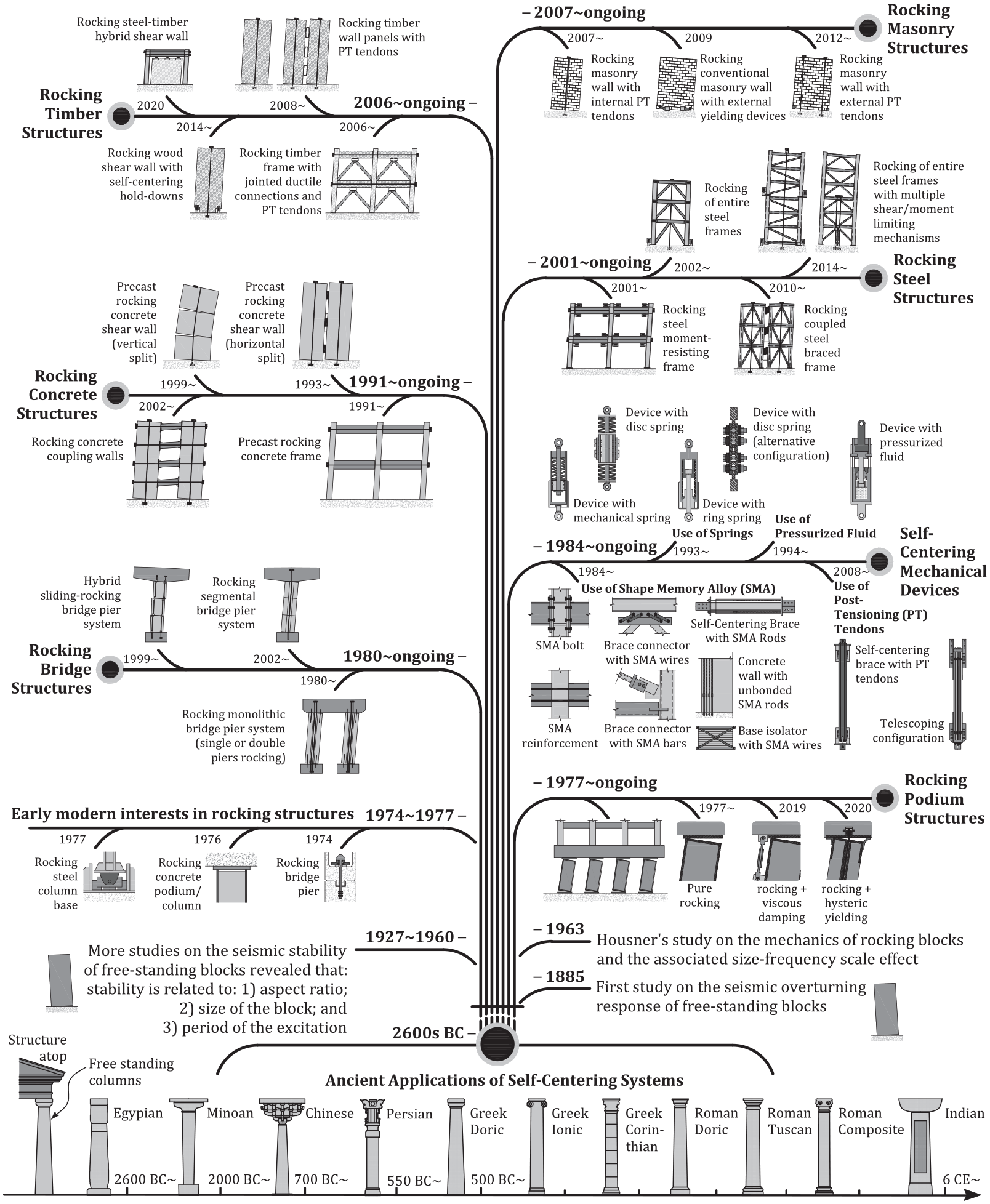
Overview of the history and recent advances in self-centering seismic-resistant structural systems.
Footnotes
Declaration of conflicting interests
The author(s) declared no potential conflicts of interest with respect to the research, authorship, and/or publication of this article.
Funding
The author(s) disclosed the receipt of the following financial support for the research, authorship, and/or publication of this article: This research is funded by Natural Sciences and Engineering Research Council of Canada.