
Abstract
This study explores the development, experimental evaluation, and optimization of a hybrid jute/PET fiber-reinforced polyester composite for lightweight automotive applications, particularly bus roof panels. 10 laminates were prepared by varying the weight fractions of Jute and PET fibers and their stacking sequences. These laminates were grouped into four categories: (1) pure Jute/Polyester laminates, (2) hybrid Jute-PET configurations with alternating layers of Jute and PET (J-P-J-P), (3) hybrid configurations with a PET-dominated outer layer (P-J-J-P), and (4) hybrid configurations with a Jute-dominated outer layer (J-P-P-J). The weight fractions of Jute and PET fibers ranged from 10% to 40%, with the remaining content being polyester resin. Mechanical testing, including tensile, compressive, flexural, and impact tests, showed that hybridizing with PET slightly reduced tensile and compressive strengths but significantly improved flexural strength, impact resistance, and reduced water absorption. The stacking sequence influenced performance, with the P-J-J-P configuration identified as optimal through the TOPSIS multi-criteria decision-making method. Optimization using HyperWorks-OptiStruct resulted in a 34.58% mass reduction in the bus roof panel, leading to an estimated fuel saving of 0.146 L per 100 km. Finite element analysis (FEA) with Abaqus validated the results, showing minimal displacement (3.88 mm) and a safety factor aligned with failure criteria. These findings demonstrate the potential of hybrid Jute/PET composites as a sustainable, high-performance alternative to steel in automotive applications.
Keywords
Introduction
Driven by the increasing number of vehicles and growing concerns over recent climate changes, the automotive industry is under significant pressure to reduce fuel consumption and emissions.1,2 A primary strategy to achieve this is the development of innovative, lightweight composite materials.2,3 Although steel, with its favorable strength-to-weight ratio, still comprises up to 65% of a vehicle’s average weight, 4 reducing the weight of individual components offers a viable solution.5,6 Consequently, composite materials, recognized for their high strength-to-weight and modulus-to-weight ratios and their resistance to corrosion and wear, are increasingly utilized in automotive engineering.7–12 Natural fibers, including sisal, jute, rice straw, flax, banana fiber, hemp, and sugarcane, are being explored as reinforcement options.6,13–20 Among these, kenaf, hemp, jute, and flax demonstrate superior flexural strength and modulus of elasticity, while sisal exhibits excellent impact properties.21–24 Jute, a fine, soft, and strong fiber, provides good tensile strength and thermal and electrical insulation.25–28
The excessive use and improper disposal of plastics have resulted in significant environmental degradation, encompassing pollution, biodiversity loss, habitat destruction, and climate change. In response to the escalating concern regarding plastic waste, waste-derived polymer composites are increasingly recognized for their sustainability and cost-effectiveness. 29 Globally, over 90% of the 400 million metric tons of plastic generated annually is discarded, often accumulating in landfills or causing environmental pollution.30,31 Within the Tigray region of Ethiopia, annual consumption exceeds 23 million plastic bottles and bags, overwhelming local waste management systems. 32 The persistent nature of plastic waste contributes to soil, water, and air pollution, while its associated harmful chemicals present considerable health risks, including respiratory disorders, liver dysfunction, various cancers, tumor development, and neurological damage in humans.33–35 Despite the durability and versatility of plastics, which have facilitated their widespread industrial and sectoral application, their adverse ecological impact is undeniable. Polyethylene terephthalate (PET) is a dominant plastic pollutant, prevalent in single-use items like water bottles, food containers, and packaging. 36 Effective strategies, including recycling, reuse, and the development of biodegradable alternatives, alongside rigorous regulations, are imperative to mitigate the detrimental environmental effects of plastic waste.36–39
In response to both environmental regulations and sustainability goals, the automotive industry is transforming by increasingly adopting lightweight, eco-friendly, multi-scale hybrid, alkaline-treated natural fiber-reinforced polymer composites for various interior and exterior components, offering cost-effective, mechanically sound alternatives to synthetic materials.3,22,40,41 Jute fibers are renewable, biodegradable, and low-cost, making them environmentally friendly alternatives with low density, high specific strength, and stiffness 42 ; moreover, jute fiber exhibits significant sound-absorbing and damping characteristics, making it an effective option for noise-controlling materials that are environmentally friendly.43,44 Subramanian et al. 45 demonstrated that optimized, unidirectional thermoplastic jute fiber tapes exhibit enhanced tensile strength over single strands, making them suitable for diverse industrial applications, including automotive. Hybrid jute fiber composites offer a cost-effective, lightweight solution for enhancing automotive fuel efficiency and sustainability. 46 Natrayan et al. 47 found that polymer coatings, particularly polyethylene, enhance jute fiber properties for automotive applications, despite reducing tensile strength compared to untreated fibers. Jute/E-glass hybrid polyester composites, with optimized stacking sequences, significantly reduce vehicle component weight and fuel consumption, providing a sustainable alternative to steel. 48 El-baky et al. 49 demonstrated that aluminum cylinders overwrapped with jute-reinforced epoxy hybrids exhibit significant crash energy absorption, making them promising lightweight structures for automotive applications. Jute-based natural fiber composites, blended with coir and polyurethane foam, exhibit effective thermal insulation properties suitable for automotive thermal insulation applications. 50 Oluwagbenga et al. 51 developed sustainable, hybrid plantain fiber/calcite-reinforced PVC bio-composites for automotive applications, optimizing natural resources. Recycled thermoplastic polyurethane (RTPU)/coconut fiber-reinforced polypropylene (PP) compounds demonstrate enhanced impact resistance and interfacial adhesion for automotive applications. 52 Kenaf fiber-reinforced epoxy demonstrates superior mechanical properties for automotive battery tray applications. 53
Both virgin and recycled PET fibers exhibit high tensile strength due to their ethylene terephthalate polymer chains and possess a relatively low density (950–1400 kg/m3) with a melting point around 245°C and an ignition temperature around 475°C. 54 PET, a cost-effective, high-performance polymer with excellent abrasion resistance, hardness, solvent resistance, and stiffness, is widely used in beverage and food packaging, leading to significant post-consumer waste.55–57 Thus, recycling this PET into rPET or natural fiber-reinforced composites provides a sustainable pathway to create valuable secondary products.58,59 Sadeghi et al. pointed out the urgent need for better PET fiber recycling and showed its potential in concrete, nonwovens, and yarns for future industries. 60 Roungpaisan et al. found PET knitted fabric ideal for recycling into r-PET fibers with enhanced properties at higher spinning speeds, guiding textile waste upcycling. 61 Tang et al. created recycled foamed concrete with waste concrete and recycled PET fibers, achieving better strength and durability for an eco-friendly recycling solution. 62 Dev et al. demonstrated that in recycled cotton/PET fiber-reinforced polyester nonwoven hybrid composites, increased cotton content improves tensile properties suitable for building, while a higher proportion of PET fiber enhances flexural and impact strength for applications such as helmets and automotive interiors. 63 Ma and Hesp found that recycled PET fibers, when longer, thicker, and possessing rough surfaces, improve the cracking resistance of asphalt mixtures at lower loading rates. 64 Foti found that recycled PET bottle fibers in concrete can reduce cracking and corrosion. 65 Hoque et al. demonstrated the economic and environmental viability of using recycled polypropylene (PP) in jute fiber-reinforced composites, which exhibit comparable water absorption and tensile properties to those made with virgin PP. 66
This research presents a novel and multidisciplinary approach to designing sustainable hybrid composites that address both vehicular weight reduction and plastic waste valorization. It introduces, for the first time, a structural laminate combining alkali-treated jute fibers with manually woven recycled PET fabrics, specifically developed for load-bearing bus roof panel applications—a material pairing not previously explored in this context. The study systematically examines the influence of fiber composition and stacking sequence, applying the TOPSIS multi-criteria decision-making method to identify an optimal configuration balancing mechanical performance and environmental resilience. Going beyond conventional experimental evaluation, the work integrates a two-stage computational strategy: HyperWorks OptiStruct is used to optimize the laminate layup for minimal weight and structural efficiency, and Abaqus Finite Element Analysis (FEA) validates the mechanical integrity of the optimized design. This combined methodology bridges the gap between sustainable material development and practical engineering application, offering a robust and scalable framework for the design of high-performance, eco-conscious composite components in the automotive sector.
Materials and methodology
Materials
Mechanical and physical properties of polyester resin.

Alkali treatment of fibers
To enhance their strength and durability, jute fibers were subjected to an alkaline treatment. The fibers were immersed in a 5% (w/w) sodium hydroxide (NaOH) solution, prepared by dissolving NaOH pellets in distilled water, a concentration found optimal by previous studies.67,68 The fiber was immersed in the solution for 4 h at room temperature (22°C). This process allowed the alkali to penetrate the fiber structure, facilitating the removal of hemicellulose, lignin, and surface impurities. Following the treatment, the fibers were thoroughly rinsed with water to eliminate residual NaOH and then dried at ambient conditions in sunlight for up to 48 h, to minimize moisture reabsorption, rendering them suitable for composite fabrication.
Similarly, to improve the performance of polyethylene terephthalate (PET) fibers in polyester-based composites, an alkaline hydrolysis treatment was applied. The PET fibers were immersed in a 10% NaOH solution at 60°C for 1 h. This 69 treatment partially cleaves ester bonds on the fiber surface, generating polar functional groups such as hydroxyl (–OH) and carboxyl (–COOH), while also increasing surface roughness. These modifications enhance the chemical compatibility between the PET fibers and the polyester matrix, leading to improved fiber–matrix adhesion. 70 Enhanced interfacial bonding promotes efficient stress transfer across the composite, thereby improving its mechanical properties and durability.24,71 After treatment, the PET fibers were thoroughly washed with distilled water and dried.
Preparation of woven PET fabric
First, PET water bottles were collected, thoroughly washed to remove contaminants, and then cut into thin strips (average width 4 mm) using a manual cutting mechanism, as shown in Figure 1. These strips were then manually interlaced at right angles (0°/90° orientation) to create the plain type woven PET fabric style with an areal density of 129 g/m2. This choice of woven architecture, aligning with the development woven structures for high-performance composites,
48
is crucial for bus roof applications. Unlike unidirectional arrangements, woven fabrics allow for a more even distribution of multi-directional loads experienced by bus roofs, including wind pressure, vibrations, and potential impacts, across both the warp and weft directions. This interlaced structure enhances the overall strength, stiffness, and impact resistance of the resulting composite material, making it a suitable candidate for demanding structural applications in the automotive, transportation, aerospace, and marine sectors.
72
The woven fabrics prepared are shown in Figure 2. Waste plastic bottle and cutting mechanism. Plain type weave style (a) Woven PET fabric and (b) Woven Jute fabric.

Composite laminate preparation
Fiber types, stacking sequences, and composition in the hybrid composites.

Where WJ—jute weight fraction, WPET—PET weight fraction, WF—fibers weight fraction, and WM—matrix weight fraction.
Testing methods
Tensile, flexural, and compressive tests were performed as per ASTM D3039/D3039 M,
74
ASTM D790-10, and ASTM D695-96, respectively,75,76 using a Microcomputer Controlled Electro-Hydraulic Servo Universal Testing Machine (Model: SI-1000 KN). The tensile test specimens were rectangular coupons with dimensions of 250 mm × 25 mm × 3 mm and a gauge length of 150 mm. Flexural specimens measured 127 mm × 12.7 mm × 3.2 mm and were tested in a three-point bending configuration with a support span of 51 mm. Compressive specimens were rectangular blocks of 12.7 mm × 12.7 mm × 25.4 mm. Impact strength was evaluated using a Charpy impact tester (Model: SI-42, 150 J) following the ISO 179/92 (2010) standard,
77
with specimens measuring 80 mm × 10 mm × 4 mm. The density and water absorption of the specimens were measured according to ASTM D792-20 and ASTM D570, respectively.78,79 All tests were carried out under ambient laboratory conditions. Representative samples before and after testing are shown in Figure 3. Samples (a) before testing and (b) after testing.
Evaluation of alternatives through TOPSIS
The Technique for Order Preference by Similarity to Ideal Solution (TOPSIS) is a widely used multi-criteria decision-making (MCDM) method designed to solve multi-objective optimization problems. It ranks available alternatives based on their relative performance across several criteria, enabling the selection of the most balanced and effective option. In this study, TOPSIS is applied to determine the optimal laminate stacking sequence and composite formulation by evaluating critical properties such as tensile strength, compressive strength, flexural strength, impact resistance, water absorption, and density. A total of 10 alternatives were considered, incorporating three distinct stacking sequences and four jute/PET composition ratios (40%/0%, 30%/10%, 20%/20%, and 10%/30%), as outlined in Table 2. The evaluation follows a structured, step-by-step TOPSIS procedure to systematically rank the alternatives based on their proximity to an ideal solution.
Decision matrix.


Weight assignment for decision criteria.


The positive and negative ideal solutions.

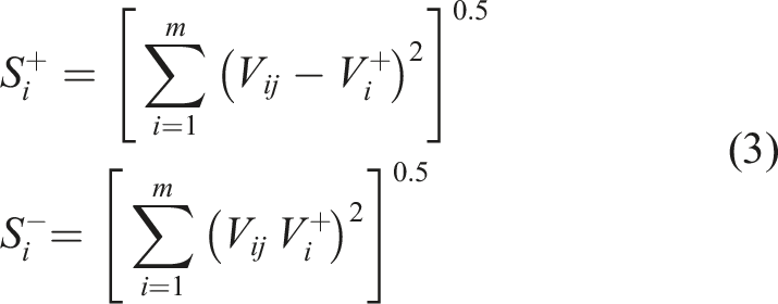
The positive ideal solution and the negative ideal solutions.


Closeness factor and rank.

Design and optimization of bus roof panel
Design parameters and materials
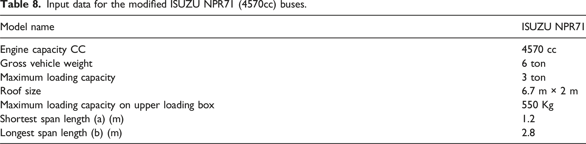
Input data for the modified ISUZU NPR71 (4570cc) buses.
Mechanical properties of composite constituents.

Mathematical modeling
The length and width of the plate surface are significantly greater than its thickness, classifying it as a thin plate. Therefore, it is analyzed using classical plate theory. In line with the assumptions of classical thin plate theory for fully supported plates, the top roof—being entirely supported by the bus body frame—is modeled as a plate with all edges fixed as shown in Figure 4. A uniformly distributed load is applied only on the loading box as shown in Figure 5. According to Timoshenko, for uniformly loaded, fully built-in rectangular plates, both deflection and bending moments are symmetrical about the coordinate axes. Boundary conditions of roof bus panel. loading conditions of roof bus panel.

The distributed load applied to the existing loading box of the bus is illustrated in Figure 4. The maximum total load acting on the loading box, denoted as F, is 5395.5 N, while the corresponding uniformly distributed load, q, is calculated to be 1605.80 N/m2.
The laminate was designed symmetrically. For a thin layer of the composite laminate, it can be assumed that the lamina is under plane stress conditions in the direction of the lamina thickness. The stress-strain relationship in the principal material, as generalized by Hooke’s law for orthotropic materials, is given by Equation (5).
Since the laminate is assumed to be under plane stress conditions, all stress components in the out-of-plane direction are zero. As a result, the stress–strain relationship in matrix form simplifies to Equation (6)
The matrix Q
ij
depends on the material properties and is given in terms of engineering constants as shown in Equation (7).
The stress–load relationships are described using Equation (8):

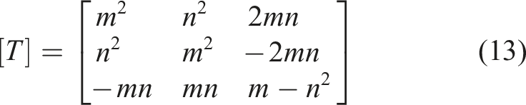
As illustrated in Figure 6, the roof panel laminate is designed to be symmetric in both geometry and material composition. In symmetric laminates, the coupling stiffness matrix [B] equals zero, indicating no interaction between in-plane forces and out-of-plane deformations. Consequently, bending-stretching coupling effects are absent—axial loads do not cause bending or twisting, and applied moments do not generate mid-plane strains. This greatly simplifies the structural behavior: when subjected solely to transverse distributed loads, the laminate primarily experiences bending. The resulting stresses are calculated using Equation (10). Furthermore, the transformation matrix, presented in Equation (13), allows conversion from global to local stress components, enabling an accurate assessment of the stresses within individual plies oriented at different fiber angles. Composite layup for the bus roof panel.


The global strain in every ply can be calculated using the equation (12) shown below.
Failure theory
Failure theories are used to compare the material stresses with the established failure criteria. For this study, the Tsai-Wu failure theory was adopted as a constraint during the analysis and optimization of the bus roof plate. The Tsai-Wu failure theory, based on the total strain energy failure theory for lamina under plane stress conditions, asserts that lamina failure occurs if the condition in Equation (14) is violated.
Optimization of roof panel
The best layup sequence, PET-Jute-PET, selected using the TOPSIS method, is subjected to further analysis and optimization using Altair HyperWorks 2019 software. In the model, PET/polyester and jute/polyester lamina materials are utilized, each characterized by their respective material properties. Altair OptiStruct offers advanced optimization capabilities, enabling the identification of optimal configurations while satisfying the imposed constraints and achieving the desired performance objectives, thereby enhancing the overall quality of the composite models. Additionally, the free-size optimization (FZO) feature in OptiStruct is employed to refine the design by optimizing the thickness of each ply on an element-by-element basis, subject to a predefined upper bound.
Design variables
Design variables are system parameters that can be adjusted to optimize performance, allowing for the selection of the best among various possible design configurations. In this study, the design variables are the thickness of each ply and the fiber orientation angle of the lamina.
Continuous variation of thickness offers more design freedom, because FZO ti allows for varying freely between the lower, 
FZO optimizes the angle indirectly by comparing the maximum element composite stress resulting from the optimized thickness that creates the minimum stress distribution developed in the structure to have a greater factor of safety.
Responses
Responses are measurable values or functions within the problem parameters that depend on the design variables and are evaluated during the solution process. In this study, the responses considered are the mass and the composite failure index.
Constraints
Constraints set the permissible lower and upper bounds on responses that are influenced by the design variables. In this study, the optimization of the bus roof panel was constrained by the Tsai-Wu failure theory, which evaluates the strength of the laminate composite based on its material properties.
Objective function
In design optimization, the objective function is either minimized or maximized by adjusting a set of design variables—such as part dimensions, material properties, and other parameters—while ensuring that all performance constraints are satisfied. The primary objective of this study is to design a bus roof panel with the minimum possible weight.
Finite element analysis in ABAQUS
The optimized bus roof panel design is validated using finite element analysis in ABAQUS to ensure the accuracy of the OptiStruct results. Both the applied loads and boundary conditions are carefully defined for the analysis. This validation process involves comparing the OptiStruct-optimized solutions with Finite Element Analysis (FEA) simulations conducted in ABAQUS to verify the reliability and consistency of the results with real-world behavior. A structural model of the composite roof panel is developed based on the optimized stacking sequence (PET/Jute/PET) and the dimensions obtained from OptiStruct, with the optimal ply orientations set at 0°/90°/0°, as illustrated in Figure 7. Meshing was done using the S4R linear mesh element type, which is a 4-node, doubly curved shell capable of handling both thin and thick structures. It incorporates reduced integration, hourglass control, finite membrane strains, and a mesh size of 0.05 as shown in Figure 8. A uniformly distributed static load of 1605.80 N/m2 is applied across the panel surface, with all edges fixed as boundary conditions as shown in Figure 9. Optimized 3D model of the roof panel showing the ply stacking sequences and orientations. Meshing using 3D element. Load defining.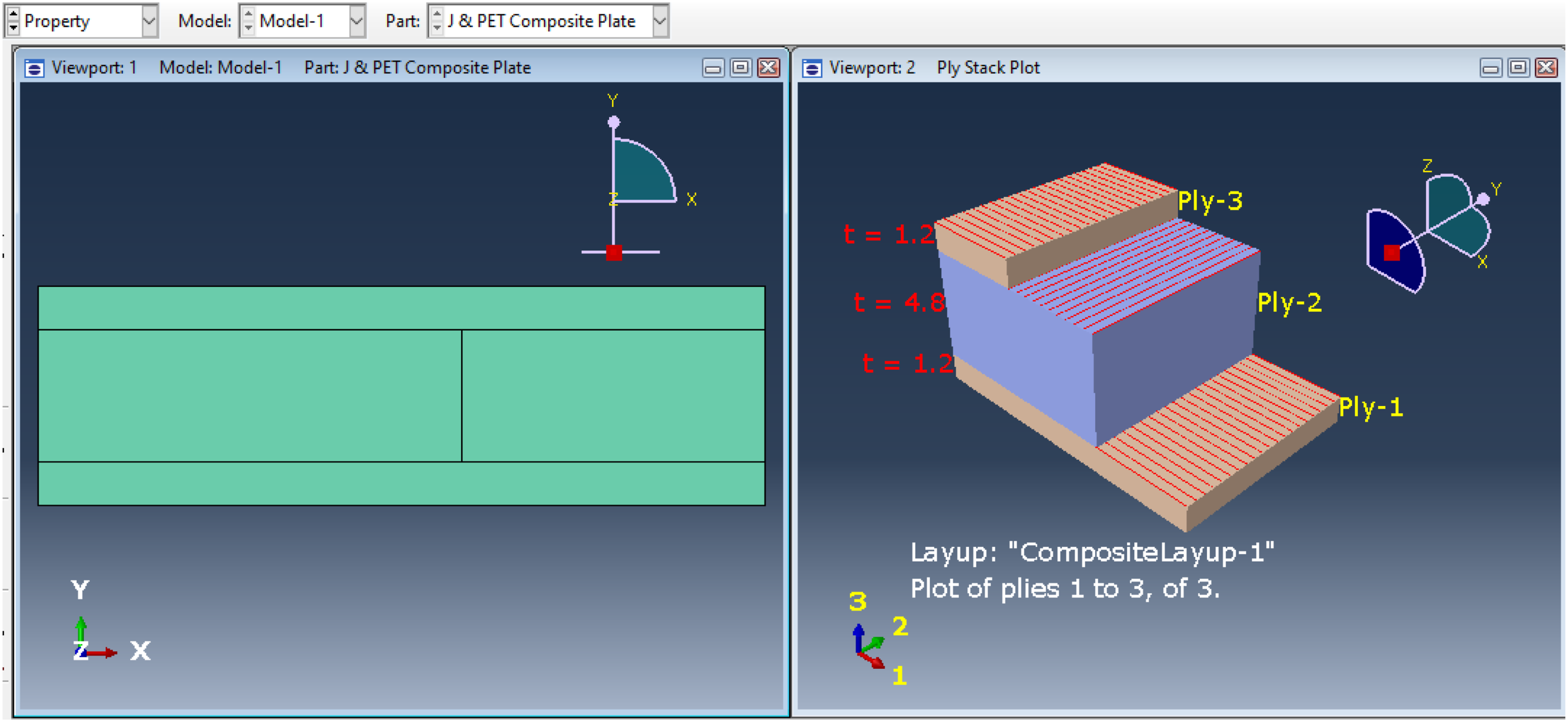


Results and discussion
Tensile strength
Five experiments were conducted for each composite laminate. The average tensile strengths of all laminates are summarized in Figure 10. The tensile strength analysis of the 10 composite laminates (L1–L10) revealed significant variations influenced by fiber arrangement and material composition. L1 (jute/polyester neat) exhibited the highest tensile strength at 89.50 MPa, outperforming the weakest sample, L10 (73.70 MPa), by 17.1%, while L5 (86.10 MPa) showed only a minor 3.95% decrease compared to L1. Laminates with PET fibers positioned in the outer layers (L5, L6, L7) demonstrated superior strength values of 86.1 MPa, 84.4 MPa, and 80.6 MPa, respectively, compared to those with jute-dominated outer layers (L2, L3, L4) or alternating ply sequences (L8, L9, L10). However, a slight reduction in tensile strength was observed as the PET content increased, likely due to the inherently lower tensile strength of PET fibers compared to jute. Although PET-dominated outer layer hybrid laminates slightly underperform compared to the neat jute/polyester laminate (L1), they demonstrate a significant improvement over other hybrid stacking configurations. The slight reduction in tensile strength relative to L1 is attributed to the lower intrinsic tensile strength of PET fibers compared to jute fibers. However, the enhanced tensile performance relative to other hybrid designs is primarily attributed to PET’s superior ductility, better compatibility with the polymer matrix, and its greater ability to delay crack initiation and propagation, which typically begins at the outer surface of the laminates. Notably, transitioning from a J-P-P-J configuration to a P-J-J-P configuration resulted in a 12.7% increase in tensile strength (from 76.4 MPa to 86.1 MPa), while adopting a P-J-P-J stacking sequence led to a 10.2% improvement (from 78.1 MPa to 86.1 MPa).These findings highlight the critical role of fiber orientation, stacking sequence, and material compatibility in hybrid composites.24,80 PET-dominated outer layers consistently offer greater structural stability and reliability compared to jute-dominated outer layers, highlighting the importance of strategic fiber placement in optimizing the performance of hybrid composites for structural applications. Average tensile strength of composite laminates.
Compression strength
Figure 11 shows the compressive strength of the 10 composite laminates (L1–L10). L1 exhibited the highest strength at 69.50 MPa, while L10 recorded the lowest at 64.60 MPa, reflecting a 7.4% difference. L5 achieved 68.90 MPa, only 0.9% lower than L1. Laminates L5, L6, and L7 (68.90 MPa, 67.80 MPa, and 66.80 MPa, respectively) demonstrated superior compressive strength compared to L2, L3, and L4 (66.80 MPa, 65.90 MPa, and 65.20 MPa) and the alternating sequence laminates L8, L9, and L10 (67.90 MPa, 65.80 MPa, and 64.60 MPa). The enhanced performance of L5–L7, characterized by PET-dominated outer layers, suggests that such stacking configurations improve compressive strength over jute-dominated ones. However, a slight reduction in compressive strength was observed as PET content increased, indicating diminishing returns with higher PET proportions. Overall, differences among stacking sequences were relatively modest, suggesting that both PET and jute fibers contribute effectively to compressive load-bearing. These results suggest that fiber stacking sequence moderately influences compressive behavior, with PET-dominated outer layers generally offering better performance. Average compressive strength of composite laminates.
Flexural strength
Five experiments were conducted for each composite laminate, and the average flexural strengths are summarized in Figure 12. The analysis of the 10 laminates (L1–L10) revealed notable variations influenced by fiber arrangement, stacking sequence, and material composition. L7 (PET-Jute-PET configuration) achieved the highest flexural strength at 194.62 MPa, outperforming the neat jute/polyester laminate (L1, 163.62 MPa) by 18.95%. L6 closely followed with 191.20 MPa, showing only a 1.79% decrease relative to L7, while L2 recorded the lowest among the PET-containing hybrids at 167.70 MPa. Unlike the tensile strength trend, where the neat jute/polyester laminate outperformed the hybrids, the highest flexural strength was observed in PET-dominated outer layer configurations, achieving an 18.95% improvement over the neat laminate. This improvement is attributed to the strategic placement of PET fibers, which enhance surface crack resistance and bending stiffness. Laminates with PET fibers in the outer layers (L5, L6, L7) consistently demonstrated higher flexural strength compared to those with jute-dominated outer layers (L2, L3, L4) or alternating ply sequences (L8, L9, L10). Transitioning from a Jute-PET-Jute configuration to a PET-Jute-PET layout resulted in an 8.55% increase in flexural strength (from 179.30 MPa to 194.62 MPa), while transitioning from a PET-Jute sequence led to a 7.91% improvement (from 180.40 MPa to 194.62 MPa). Additionally, increasing the PET fiber weight fraction consistently improved the flexural strength across all stacking sequences, further emphasizing PET’s role in enhancing bending performance. These findings highlight the critical importance of precise layer arrangement and material composition in optimizing flexural behavior. PET-dominated outer layers consistently provide superior flexural stability and reliability compared to jute-dominated configurations. Average flexural strength of composite laminates.
Impact strength
Five experiments were conducted for each composite laminate, with the average impact strengths summarized in Figure 13. Analysis of the 10 laminates (L1–L10) revealed notable variations attributable to fiber stacking sequence and material composition. Notably, the L7 (PET-Jute-PET) configuration exhibited the highest impact strength of 85.6 KJ/m2, representing a 43.1% improvement over the neat jute/polyester laminate (L1, 59.8 KJ/m2). This superior performance is attributed to PET fibers in the outer layers, which enhance toughness and energy absorption, thereby hindering surface crack initiation and propagation. Laminates with PET fibers in the outer layers consistently demonstrated higher impact resistance than those with jute-dominated outer layers, highlighting the critical role of PET in reinforcing the laminate surface. For instance, L5 (PET-Jute-PET) achieved 73.5 KJ/m2, outperforming L2 (Jute-PET-Jute, 65.2 KJ/m2) by 12.7%. Similarly, L6 exhibited a 14.0% higher impact strength than L3 (increasing from 71.3 KJ/m2 to 81.3 KJ/m2), and L7 showed a 13.5% improvement over L4 (rising from 75.4 KJ/m2 to 85.6 KJ/m2), despite maintaining the same jute/PET weight ratio. Furthermore, transitioning from an alternating sequence (L10: 73.5 KJ/m2) to the PET-Jute-PET configuration (L7: 85.6 KJ/m2) resulted in an additional 16.5% enhancement, underscoring the significance of layer arrangement. These results demonstrate that fiber type, stacking sequence, and PET-dominated outer layers critically influence impact resistance, explaining L7’s outstanding performance and providing insights for designing high-impact hybrid composites. Average impact strength of composite laminates.
Density
The experimental and theoretical densities of composite laminate results summary.

Water absorption
Water absorption at saturation.


Water absorption rate.
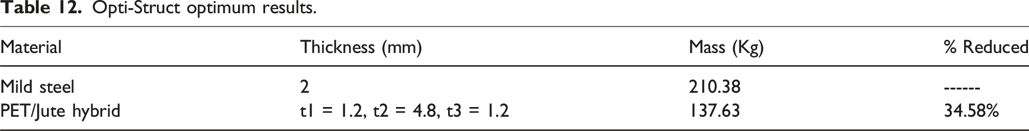
Optistruct optimization results
Opti-Struct optimum results.
Validation of results using FEA in ABAQUS
Finite element analysis (FEA) using Abaqus software was conducted to evaluate the stress distribution within the composite bus roof plate, consisting of PET polyester and jute-polyester laminates. To compares FEM with experiments indirectly via material properties (experimental inputs for FEM) but not directly for structural performance, For the ply-1, FEA results reveal S11 of 13.42 MPa and 6.64 MPa and S22 of 23.61 MPa and 17.41 MPa, respectively, at the edges, while experimental values are higher at 67.5 MPa (transverse tensile) and 62.2 MPa (transverse compression). Also, this indicates that the material, though stressed at the edges, remains within safe limits. The primary difference between ply-1 and ply-3 is the direction of the stress, while the stress magnitudes remain comparable. For the ply-2 shows a maximum normal stress of 5.53 MPa in the fiber direction (S11) and a transverse stress of 4.12 MPa, both are lower than those in PET polyester fiber-reinforced plies. Despite this, the jute ply maintains a reasonable load-bearing capacity, with a shear stress (S12) of 4.58 MPa. Experimental results, however, reveal much higher values: 69.4 MPa for longitudinal compression, 58.1 MPa for transverse tension, and 25.5 MPa for shear strength. FEA indicates that the stresses in the jute ply are well below its actual capacity, confirming that the ply is not overstressed. Deviations due to idealized FEM (no voids/porosity) versus real samples; safety factors confirm design conservatism. To assess the safety of each ply, the maximum stress theory was applied, which calculates the safety factor by dividing the material’s strength by the maximum stress experienced by the respective ply. All plies exhibited safety factors greater than 1, indicating safe operation under the expected loads. Among them, ply 3 (the PET polyester outer layer) showed the lowest safety factor of 2.634, attributed to transverse compressive stress, with its stress distribution illustrated in Figure 15. Despite being the lowest, this safety factor remains above the recommended threshold for vehicle roof structures, ensuring that ply 3 operates within acceptable limits. Ply 1 (the other PET polyester outer layer) exhibited a minimum safety factor of 2.855 against transverse tensile stress, highlighting strong tensile performance. Meanwhile, the jute-polyester middle layer (ply 2) demonstrated a significantly higher minimum safety factor of 6.55, indicating a substantial margin of safety. When comparing the minimum safety factor of ply 3 (2.634) from the maximum stress theory with the Tsai-Wu failure criterion (which predicted a composite safety factor of 2.658), the results are highly comparable. This close alignment between the two methods confirms the robustness of the composite design. Although ply 3 is expected to be the first to fail under increasing load due to transverse compressive stresses, the current safety factor ensures that failure is unlikely under normal operating conditions. Overall, the safety factors derived from both the maximum stress theory and Tsai-Wu failure criteria validate the reliability of the optimized composite bus roof plate, confirming that it will operate safely and efficiently under expected service loads. Transverse stress distribution (S22) across the critical Ply 3 in the hybrid composite.
Moreover, the resulting displacement magnitude of the optimized bus roof plate, shown in Figure 16, was found to be U = 3.88 mm, representing the maximum deformation of the composite laminate under the applied load. This low level of deformation indicates that the structure exhibits high stiffness, an important characteristic for automotive structural components. Therefore, the results obtained from the OptiStruct optimization process were successfully validated through detailed finite element analysis using Abaqus, confirming the effectiveness and reliability of the optimized design. Deformation of the hybrid composite roof panel.
Conclusion
This study focused on the development, experimental evaluation, and optimization of a sustainable hybrid Jute/PET fiber-reinforced polyester composite for lightweight automotive applications, particularly for bus roof plates. The experimental, analytical, and numerical investigations led to the following conclusions. • The hybridization of jute fibers with PET fibers influenced the mechanical performance of the composite. A slight decline in tensile strength was observed upon hybridization compared to the pure jute laminate. Similarly, a slight reduction in compressive strength was recorded, indicating that the hybrid laminate is marginally less capable of bearing compressive loads than pure jute laminates. However, flexural strength improved after hybridization, demonstrating better performance under bending loads. The hybrid laminate also exhibited enhanced impact strength compared to the jute-only laminate, indicating better energy absorption capabilities. • Hybridization of jute with PET fibers significantly reduced the water absorption of the composite, owing to the hydrophobic nature of PET. Additionally, the density of the hybrid laminate remained considerably lower than that of conventional materials such as steel, enhancing its suitability for lightweight automotive structures. • The stacking sequence had a significant impact on the composite’s overall performance. The P-J-J-P layup sequence was identified as the optimal configuration using the TOPSIS multi-criteria decision-making method, providing a favorable balance between mechanical strength and moisture resistance. • HyperWorks-OptiStruct optimization successfully minimized the mass of the bus roof plate by 34.58%, reducing its weight from 210.38 kg to 137.63 kg. This mass saving is projected to yield a fuel saving of approximately 0.146 L per 100 km traveled, thereby improving vehicle efficiency and supporting environmental sustainability initiatives. • Finite element analysis (FEA) performed using Abaqus validated the optimization results. The minimum safety factor obtained using the maximum stress theory (2.634) was closely comparable to the value derived from the Tsai-Wu failure criterion (2.658), confirming the robustness and reliability of the optimized design. Furthermore, the maximum displacement under service load was limited to 3.88 mm, indicating excellent structural stiffness suitable for automotive applications.
Overall, the findings demonstrate that hybrid Jute/PET composites present a sustainable and effective alternative to traditional steel structures in automotive applications. Despite slight reductions in tensile and compressive strengths compared to pure jute laminates, the hybridization significantly enhanced flexural and impact properties while reducing water absorption. The lightweight nature and favorable mechanical performance of the optimized hybrid composite make it ideal for structural automotive components, such as bus roof panels, contributing to significant weight reduction, improved fuel efficiency, and enhanced environmental sustainability.
Footnotes
Funding
The author(s) disclosed receipt of the following financial support for the research, authorship, and/or publication of this article: This research was supported by the Faculty of Mechanical and Industrial Engineering and the Faculty of Civil Engineering at the Ethiopian Institute of Technology Mekelle (EIT-M), Mekelle University, which provided essential materials, laboratory facilities, and financial resources.
Declaration of conflicting interests
The authors declared no potential conflicts of interest with respect to the research, authorship, and/or publication of this article.