
Abstract
Fibre-reinforced composites, such as carbon fibre-reinforced polymers (CFRP) and glass fibre-reinforced polymers (GFRP), are widely utilized in engineering applications for their exceptional strength and stiffness. However, their brittle failure and limited impact resistance hinder broader applications, especially in high-impact environments. Improving impact resistance is therefore critical for advancing their performance and expanding their usability. This study explores the development of novel composites with components hybridized on microscale that integrate high-strength fibres (e.g., carbon, glass) with ductile fibres (e.g., steel, aramid) through the fabrication of hybrid yarns featuring highly dispersed fibre components, rather than conventional layer-wise configurations. Three distinct hybrid composite concepts were developed using innovative fibre combinations and manufacturing techniques: Concept 1 (carbon, aramid, and thermoplastic filament yarns), Concept 2 (glass, stainless steel, and polypropylene yarns), and Concept 3 (recycled aramid, carbon, and thermoplastic fibres). The experimental results (tensile and Charpy impact tests) show that by using a specific combination of fibre materials, the properties: tensile strength, impact strength, and energy absorption of the hybrid composite can be specifically modified to meet the needs of the application. Notably, Concept 1 exhibited the highest tensile strength, while Concept 2 excelled in ductility and energy absorption. The hybrid yarns, produced using air texturing and carding techniques, showed optimized tensile properties through fine-tuning of air pressure and overfeed rates during manufacturing. These findings underscore the potential of hybrid composites with highly dispersed components in engineering applications requiring tailored properties.
Introduction
The brittleness and poor impact resistance of traditional fibre-reinforced composites, such as carbon fibre-reinforced polymers (CFRP) and glass fibre-reinforced polymers (GFRP), pose significant challenges in engineering applications. These materials, while exhibiting exceptional strength and stiffness, are prone to sudden, catastrophic failure, which raises safety concerns and limits their predictability.1,2 The lack of residual strength, coupled with inadequate resistance to impact and crash scenarios, further restricts their reliability in demanding environments. 3 Addressing these limitations is crucial for expanding their applicability in fields requiring high-performance and robust materials. 4 To overcome these challenges, hybrid composites have emerged as a promising alternative, combining the high stiffness and strength of conventional fibres with the enhanced ductility and energy absorption properties of metallic fibres 5 and aramid fibres. 6 These novel material systems offer a pathway to mitigate brittle failure while enhancing toughness and energy absorption capacity, addressing the critical limitations of traditional fibre-reinforced composites.7,8
Historically, hybrids have been examined since the 1970s to improve impact strength and post impact performance. One focus of the research was to investigate the influence of hybrid fibre composites on fracture toughness. It has been shown that the combination of fibres with high elongation at break, such as glass fibres (GF), and fibres with low elongation at break, such as carbon (CF) fibres, can result in improved mechanical properties. Zweben et al. analyzed hybrid composites of carbon and glass fibres and found that the elongation at break of these hybrids was higher than that of pure carbon fibre composites. 9 Such effects, where hybrid materials exhibit different properties than predicted by linear mixing rules, are referred to as ‘hybrid effects’. In this context, Thorat and Lakkad investigated the fracture toughness of unidirectional epoxy resin hybrid composites reinforced with glass and carbon fibres. 10 The results showed a significant positive hybrid effect in terms of critical energy release rate and critical stress intensity factor, resulting in improved crack propagation resistance. However, there is no general consensus that hybridization always has a positive effect on other mechanical properties such as compressive, flexural or shear strength. In fact, the effects on these properties are often inconsistent or can even be detrimental. For example, Marom et al. reported a negative hybrid effect on fracture energy in hybrids of E-glass and carbon fibres. 11
In addition to carbon (CF) and glass (GF) fibres, hybridization with materials such as self-reinforced polypropylene (SRPP) introduces ductility into carbon fibre-reinforced polypropylene composites, allowing gradual failure rather than brittle fracture. 12 Carbon-fibre/SRPP hybrids provide a unique combination of stiffness, toughness, and density that retains strength even when notched. 13 Hybrid glass/steel fibre reinforced epoxy composites have shown a significant improvement in energy absorption prior to failure and material re-centering capability, which is a significant advance over conventional fibre reinforced polymers which do not have such ductility. 14 Although a single fibre type can sometimes achieve the desired ultimate strength, the hybrid approach offers improved toughness, residual strength, and controlled failure behaviour.
One factor contributing to the improved performance of hybrid composites with both ductile and high strength fibres is the phenomenon known as the ‘crack bridging’ mechanism. This mechanism is critical to understand the mechanical behaviour of hybrid composites under different loading conditions as it significantly influences the ability of the material to redistribute stresses and delay crack propagation. 15 It involves two critical aspects: (1) local stress concentrations resulting from fibre fracture events and (2) the transfer of fibre-matrix loads to adjacent high ductility materials such as steel or aramid fibres. In cases where fractures occur in the less ductile fibres, such as glass or carbon fibres, the failed fibres still can transfer loads to the regions before and after the fractures, as the neighbouring fibres play a crucial role in transferring stress. 16 The stresses are effectively dissipated by the elongation of the highly ductile fibres surrounding the crack, resulting in progressive fracture behaviour. Also the inclusion of short fibres into brittle matrices enhances ductility properties through a complex failure process that involves hardening and softening stages due to matrix micro-cracking and fibre stress bridging across matrix micro-cracks. 17 Singh et al. were able to reduce the damaged area of impact specimens by up to 48 % by using short glass fibres compared to composites with continuous filaments. 18 Wang et al. improve the interlaminate properties through the use of short fibre modified resins. 19 This can be attributed to the more uniform distribution of short fibres, which mitigates stress concentrations – a known issue in fibre-metal laminates (FML) – and reduces delamination risk. 20 Furthermore, when impacted, short fibres tend to pull out from the matrix rather than fracture. This pull-out mechanism consumes a significant amount of energy. 21
Understanding the full potential of hybrid composites also requires examining the scale of hybridization. Various studies have been conducted to investigate the influence of hybridization on composite response and mechanical behaviour. Egner et al. proposed a new estimation method based on the equivalence of internal strain energy between heterogeneous and quasi-homogeneous configurations of hybrid composites. 22 Casapu et al. explored the ply-level hybridization technique for tailoring the composite response by mixing different types of unidirectional carbon-fibre-prepregs. 23 These studies demonstrate that the hybridization approach has a significant influence on the mechanical properties of the hybrid composites and highlight the potential for tailoring these properties through hybridization techniques. For modern hybrid composites hybridization takes place at different structural levels based on the selected manufacturing processes: macroscale, mesoscale, and microscale.24,25
Macroscale
At the macroscopic scale, a notable technique is laminar hybridization, where alternating layers of metal sheets and fibre reinforced polymers (FRPs) are systematically combined. These composites, known as fibre-metal laminates (FMLs), include metal sheet layers together with FRPs, as seen in examples such as CARALL (carbon fibre reinforced epoxy/aluminium foil laminate), ARALL (aramid fibre reinforced epoxy/aluminium foil laminate), and GLARE (glass fibre reinforced epoxy/aluminium foil laminate). 26 The fabrication of FMLs typically involves Lay-Up Process and Lay-Up Process Autoclave Curing or Out-of-Autoclave (OoA) Curing, along with additional post-processing steps like trimming and surface finishing. However, under loading conditions, the macroscopic layer-by-layer arrangement can cause stress concentrations at the interfaces between the aluminium foil and the fibre-reinforced composite layers, resulting in layer delamination and premature failure of the composite components.27–29 This phenomenon results from inherently poor interlayer adhesion due to geometrically constrained, small interfaces between aluminium foil and FRC layers, resulting in low maximum shear stress transferability. 30 Improving adhesion or maximum shear stress transferability at the interfaces requires costly surface functionalization of the aluminium foils and/or high performance fibres, 31 such as sandblasting, etching, coating, or plasma-based methods. 32 Especially in forming processes with significant deformation, high shear stresses occur at the interlaminar interfaces, limiting the applicability of fibre-metal laminates (FMLs) for complex component geometries. In addition, FMLs present economic challenges, including manual lay-up steps or the use of expensive robotic techniques, expensive autoclave processing, long processing times, and significant joining effort.
Mesoscale
Mesoscopic hybrids refer to the design and engineering of materials optimized at an intermediate scale between the microscopic and macroscopic levels. The fabrication of these hybrids involves advanced techniques such as the fabrication of textile architectures, including woven and nonwoven fabrics, composed of different types of filaments such as carbon fibres (CF) and aramid fibres (AR). 6 In addition, Fused Deposition Modeling (FDM) is used for precise deposition of fibres, enabling the controlled fabrication of complex mesostructural patterns. 33 In the case of mesoscale hybridization, as in macroscopically hybridized composites, the mechanical performance of individual reinforcement components in the resulting composite cannot be fully exploited due to well-defined interlaminar interfaces and associated drawbacks.
Microscale
At the microscale, hybridization occurs at the fibre level, where filaments of different types are blended to form hybrid yarns or tape structures. Techniques such as texturing 34 and online spinning 35 facilitate the integration of dissimilar filament yarns, enabling the creation of these microscale hybrids. This approach offers a viable strategy to move beyond the traditional layered configuration of FMLs and the mesoscale arrangement, allowing for the uniform integration of high and low elongation fibres. By doing so, a substantial array of load-bearing interfaces is established at the microscale, enhancing the material’s overall mechanical performance. 36 This will result in a homogeneous microstructural blend that will reduce the stress concentrations that occur at the interlaminar interfaces and thus decrease the tendency to delaminate. Compared to sequentially layered hybrids, highly dispersed fibre reinforced composites have a significant amount of interfacial regions between fibres and matrix. As energy can also be dissipated by delamination under loading conditions, 37 the abundance of these small interfacial regions can facilitate stress dissipation homogenously across the cross-section, for example by pull-out mechanisms. As a result, significant stress concentrations, such as those observed in FML interfaces, can be avoided.
Despite these advances, the study of microscale dispersed fibre components in hybrid composites is still in its initial stages. To address this gap, our research aims to provide new insights into how these materials can improve impact strength and failure behaviour. Therefore, the main objective of this study is to investigate and develop composite materials with improved impact resistance characterized by progressive failure tendencies. The research aims to investigate the interplay of different material pairings, such as high elongation fibres (Aramid-, Steelfibres) combined with low elongation fibres (Carbon-, Glasfibres). In addition, the comparative effect of using virgin continuous filaments versus staple fibres from fabric residues will be investigated (see Figure 1): (1) Concept I: A Hybrid Composite consisting of Aramid (AR), Carbon (CF), and Thermoplastic Filament (TP) yarns, which have been combined using a modified air jet texturing technique to create endless filament yarns. Compared to carbon fibres, aramid fibres have a higher elongation at break. The combination of carbon fibres and aramid is therefore expected to produce a composite material with a balanced stiffness and strength profile and improved impact resistance. (2) Concept II: Lastly, a Hybrid Composite has been formulated using Glass (GF), Stainless Steel (StS), and Thermoplastic Filament yarns, which were combined using a modified Air Jet Texturing Machine. Steel fibres were also selected to develop composites with improved impact resistance and residual strength due to their high ductility. However, as composites incorporating carbon and metal fibres are susceptible to corrosion, glass fibres were chosen as an alternative for this concept. (3) Concept III: Another hybrid composite consists of staple fibres derived from aramid (rAR) and carbon (rCF) textile waste, specifically fabric residues from cutting processes, combined with thermoplastic (TP) fibres. These fibres undergo carding, drawing and spinning processes during production. Due to their recycled fibre composition, these composites offer environmental benefits. The aim here is to determine whether composites made from recycled fibres can achieve performance comparable to concepts 1 and 2, which use virgin filaments. Illustration of the key concepts discussed in this study.

By carrying out various investigations on the composite specimens, the aim is to gain a comprehensive understanding of the influence of the material concepts on the mechanical properties of the hybrid composites, with the ultimate aim of improving their impact strength and tailored failure behaviour for various engineering applications.
Materials and methods
To overcome the inherent heterogeneity of conventional layered fibre-reinforced composites, this study adopts a microstructural hybridization approach through the development and application of hybrid yarns. By intimately intermixing dissimilar fibre types at the yarn level, the method promotes fine-scale dispersion of reinforcement phases, thereby enhancing property uniformity, reducing void content, and eliminating the need for traditional layered architectures. These hybrid yarns serve as the structural basis for unidirectional textile preforms, which are subsequently consolidated via thermoforming to produce thermoplastic composites with improved homogeneity and mechanical performance.
The composite systems investigated in this study incorporate a variety of filament and staple fibre materials, selected based on their mechanical performance and processing compatibility. These fibre materials were used to manufacture the hybrid yarns.
This study investigates three different hybrid yarn configurations and the composites based on them: Concept 1 uses virgin carbon and aramid filament yarns, combined via air texturing. Concept 2 involves hybrid yarns combining glass and stainless steel fibres. Concept 3 is based on blends of waste carbon and aramid fibres (from production scrap, e.g., weaving edge waste) processed via carding and flyer spinning.
Fibre and filament materials used in the study and their respective properties.

The glass fibre (GF) yarn, with a fineness of 68 tex, was of type EC9 Z28 302P and manufactured by P-D Glasseiden GmbH Oschatz (Germany). GF is known for its high tensile strength and excellent resistance to environmental degradation, making it ideal for reinforcing polymer matrices in load-bearing and durable applications.
Polypropylene (PP) yarn, with a fineness of 33 tex, was of type Prolen HP 330/66 (white, untwisted) and sourced from Chemosvit Fibrochem (Czech Republic). PP offers lightweight characteristics, high chemical resistance, and good processability, which contribute to the overall flexibility and reduced weight of the hybrid composites.
For the stainless steel (StS) yarn, 10 monofilaments of acid-resistant chrome-nickel steel wire (1.4301) were spooled together to create a yarn with a fineness of 225 tex. These monofilaments, each with a diameter of 60 μm, were provided by Heinrich Stamm GmbH (Germany). StS provides high ductility, which enhances the composite’s structural integrity even after intensive.
Concept 3 uses carbon and aramid rovings (60 mm rCF, 50 mm rAR) from weaving edge waste. The mean fibre lengths were 60 mm for waste carbon fibres (rCF), 50 mm for waste aramid fibres (rAR), and 60 mm for polyamide 6 (PA6). The use of these rCF contributes to sustainability goals while maintaining suitable mechanical and thermal properties for composite applications.
The selection of different thermoplastic fibres as matrix materials following the thermopressing process – polypropylene (PP) for Concept 2 and polyamide 6 (PA6) for Concepts 1 and 3 – was based on considerations of material performance and structural optimization. PA6, being hygroscopic, promotes moisture absorption when used in proximity to steel, thereby increasing the risk of corrosion. Consequently, its application was limited to configurations where this risk could be managed. In contrast, PP was employed exclusively in Concept 2 to counteract the high density of the embedded steel fibres. Owing to its lower density (0.92 g/cm3) compared to PA6 (1.14 g/cm3), PP effectively contributed to maintaining the lightweight character of the composite structure. Standardizing the matrix material across all concepts would have constrained the optimization potential, thereby limiting the ability to adapt each composite system to its intended application.
The single-fibre tensile tests were conducted to quantify the energy required to fracture individual filaments, which is critical for understanding the fracture behaviour of composite materials. Filaments were extracted from yarns for testing. A Vibromat ME (Textechno, Germany) was used to characterize the stress–strain behaviour of carbon fibre (CF), glass fibre (GF), polyamide 6 (PA6), and polypropylene (PP) single filaments in accordance with DIN EN ISO 5079. Tests were performed using a gauge length of 20 mm, a crosshead speed of 10 mm/min, and a 100 N load cell. Before mechanical testing, the fineness (linear density) of each filament was measured on the same instrument according to DIN EN ISO 1973, using the resonance frequency method. The tex values obtained (g/1000 m) were used to normalize tensile strength results, which were reported as specific strength (N tex-1). During testing, the stress–strain curves were recorded, and the area under each curve was integrated to determine the fracture energy (Joules).
Through investigating three different concepts of hybrid composites with varied fibre combinations and manufacturing techniques, the study seeks valuable insights into the fibres’ energy absorption potential. These findings will contribute to achieving progressive failure behaviour in the composites, enhancing impact resistance, and tailoring their performance for engineering applications.
Yarns production and analysis methods
For Concepts 1 and 2, where filament yarns were employed, hybrid yarns were produced using an air texturing technique on a modified RMT-D machine (Type RMT-D, SSM Schärer Schweiter Mettler AG, Switzerland). For detailed experimental set-up information, refer to Ref. 38. In order to produce the hybrid yarns as required, the Tandem Air jet was integrated into the existing air texturing machine.
To optimize the operational parameters of the newly developed tandem air jet system, it is crucial to determine the optimal settings through a systematic investigation. The parameters under study include Overfeed, the force exerted by the pre-spreading device, air pressure of the HiMeJet, and the air pressure of the Temco LD4 Jet. The influence of these parameters on yarn properties was assessed by measuring the tensile strength and coefficient of variation of yarns produced under varying conditions: Overfeed (2%, 7%, 11%), force of the pre-spreading device (2, 4, 6 N), air pressure of the HiMeJet (2, 3, 4 bar), and air pressure of the Temco LD4 Jet (2, 3, 4 bar).
The tensile strength of hybrid yarns was evaluated using a tensile test in accordance with DIN EN ISO 2062, employing a Zwick Z 2.5 tensile strength testing apparatus (Zwick GmbH and Co., Germany) equipped with external strain measurement. A gauge length of 250 mm was utilized for each test, with a minimum of 15 replicates conducted to ensure statistical reliability. The coefficient of variation in yarn properties was determined gravimetrically by measuring the mass of randomly selected 1-m yarn segments, ensuring a representative sampling across the yarn length. The empirical data obtained from these measurements were used to calculate mean values, and exponential functions were fitted to the results, providing preliminary insights into the relationships between individual process parameters and yarn properties.
To identify the most suitable parameter combinations, more complex predictive models were required. Various models were assessed, including Linear Regression, Random Forest, K-Nearest Neighbors, Lasso, Ridge, Gradient Boosting, and Support Vector Regression. The dataset was divided into a training set (80%) and a validation set (20%) to facilitate model training and evaluation. Model performance was quantified by calculating the Mean Squared Error (MSE), using the Scikit-learn library. 39 The model with the lowest MSE was selected for further analysis and prediction. Additionally, to visualize the interactions and dependencies among the most influential variables, response surface methodology (RSM) was employed. This approach allowed for the simultaneous visualization of the effects of three input variables on the response, thereby facilitating a deeper understanding of the system’s behaviour.
For Concept 3 the hybrid yarn development process consists of several distinct stages. During the fibre preparation stage, aramid and carbon fibres were blended using an integrated feeder unit on a modified carding machine. The blending process was designed to achieve target fibre volume fractions of 18% aramid and 32% carbon fibres, consistent with the specifications of Concept 1. This uniform fibre blend served as the foundational input for all subsequent processing steps. Afterwards a modified carding machine is used to form partially oriented card slivers with this blend of fibres. The drawing stage further aligns the fibres and reduces their inhomogeneity for increased strength. This step has been conducted using a modified Rieter RSB-D40 (Rieter Holding AG, Switzerland) draw frame. Finally, in the flyer spinning stage, the drawn fibres are twisted together in a F15 flyer spinning machine (Rieter Holding AG, Switzerland) to produce hybrid yarns with settings of twist intensity of 30 twists per metre (tpm) and targeted linear density of 800 tex. This comprehensive process enables the creation of hybrid yarns with improved properties suitable for various applications.
Fabrication of composites
To produce a unidirectional (UD) thermoplastic composite from the hybrid yarn, the hybrid yarn was wound on a metal frame with a uniform density winding using the winding technique on the FW122 winding machine from IWT (Germany). Subsequently, the UD fabric samples were consolidated using the P300 PV thermal laboratory press from COLLIN Lab & Pilot Solutions GmbH (Germany). The pressing parameters are shown in Figure 2. Pressing parameters used for fabric consolidation: (a) Concepts 1 and 2 and (b) Concept 3.
For the tensile tests of the composites, specimens were cut from the finished panels in the 0° direction (parallel to the fibre axis) using a precision table saw with a blade suitable for fibre reinforced composites. These specimens had dimensions of 250 ± 1 mm in length, 25 ± 0.2 mm in width, and 2 ± 0.2 mm in thickness, following the guidelines of DIN EN ISO 527-5/A/2 standards. Additionally, composite specimens for the Charpy impact test were prepared, conforming to DIN EN ISO 179-1, with dimensions of 40 ± 1 mm × 15 ± 0.2 mm × 2 ± 0.2 mm. In order to obtain information of the composite cross section by microscopic images, specimen with dimensions of 20 ± 1 mm × 10 ± 0.2 mm × 2 ± 0.2 mm has been cut from the composite.
Testing of composites
The manufactured composite specimens were used for characterization in mechanical tests, which were used to evaluate their performance and validate the influence of the material concepts on the mechanical properties of the hybrid composites. All testing equipment was housed in a temperature and relative humidity controlled laboratory, maintained at 23 ± 2°C and 65 ± 2%, respectively.
Composite tensile tests
The tensile tests on the composite specimen were conducted using a Zwick Z100 tensile testing machine from ZwickRoell (Germany) with a 100 kN load cell. The test speed was set to 2 mm/min. The quasi-static tensile properties of the composites specimen were determined following the test method outlined in DIN EN ISO 527.
Charpy impact
The impact tests were performed using a Charpy pendulum impact tester model CEAST 9050 from Instron GmbH (Germany), which is based on the Charpy impact test principle according to ISO 179. A pendulum hammer with a kinetic energy of 15 J was used.
Tensile tests after impact
To characterize the post-failure behaviour, the residual tensile strength of impacted specimen was determined. Composite specimen subjected to Charpy impact tests that exhibited non-catastrophic damage (i.e., without complete fracture) were selected for subsequent tensile testing. Testing was performed using a Zmart.Pro universal testing machine (ZwickRoell, Germany) equipped with a 10 kN load cell. A preload of 50 N was applied, and testing proceeded at a constant crosshead speed of 2 mm/min. The gauge length was set to 20 mm. The stop criterion was defined as reaching 40% of the peak force observed during the tensile test to effectively capture the post-failure behaviour of the material; this value was selected based on common practice for post-impact residual strength assessment. Evaluation beyond this strain range was considered outside the scope of this investigation.
Microscopic images
To analyze how individual components mix within composites fabricated from hybrid yarns, the composite specimens were embedded in an epoxy resin matrix and cured at room temperature. After embedding, samples underwent mechanical polishing using progressively finer abrasive papers (up to grit size 2000) followed by cleaning with ethanol. Cross-sectional images of polished composites were captured using an optical microscope (Axio Imager M1m, Carl Zeiss, Germany). Optical microscopy was selected due to its suitability for identifying fibre distribution, fibre-matrix interfaces, and possible defects such as voids or micro-cracks. Furthermore, microscopic images of fracture zones post tensile and impact testing were analyzed to elucidate composite structural patterns and damage mechanisms.
Results
Single fibre tensile test
Concepts and hybrid yarn properties.


Results of single fibre tensile tests with (a) average stress–strain curves, (b) energy required to break, and (c) schematic representation of the calculation of the areas under the curves.
Results of the single fibre tensile tests.

To quantitatively assess the potential of these fibres for energy absorption in damage-tolerant composites, the area under the stress–strain curve, representing mechanical work (
Results depicted in Figure 3(b) and (c) indicate that the StS filament achieved the highest mechanical work (7.46 ± 0.15 J/mm2), substantially exceeding AR, CF, and GF fibres. This substantial energy dissipation capability of StS fibres strongly supports the hypothesis that incorporating these fibres could notably enhance impact resistance and improve the post-failure performance of composite materials. Further comparative analysis of single versus hybrid fibre composites is addressed in subsequent sections (reference relevant later sections explicitly).
Yarn production analysis
The initial step in yarn production was to analyze the influence of system parameters on yarn properties, specifically focusing on tensile strength and yarn uniformity. Empirical correlations derived from experiments are presented in Figure 4. The Analysis reveals that increasing air pressure in the air jets correlates with reduced tensile strength and increased yarn non-uniformity, as quantified by a higher coefficient of variation. This decrease in strength and increase in unevenness are likely due to fibre damage resulting from excessive mechanical stress applied by elevated air pressure. In contrast, the force applied by the spreading unit showed no statistically significant effect on the yarn properties. Moreover, an increase in overfeed tended to reduce tensile strength and increase non-uniformity, possibly due to prolonged exposure of the yarn to mechanical stresses within the air jets, consequently enhancing fibre damage and uneven yarn structure. Illustration of the Tandem Air Jet system components with second-degree polynomial regression applied to the empirical data determined from the yarn characterizations.
Figure 5(a) presents the correlation matrix calculated using Pearson’s correlation coefficients, highlighting critical relationships among the system parameters and yarn properties. The analysis reveals that both Air Pressure 1 and Air Pressure 2 exert the most substantial influence on the tensile strength and coefficient of variation (CV) of the hybrid yarn. Moreover, a significant negative correlation between CV and tensile strength indicates that increased variability (higher CV) in yarn structure corresponds strongly with reduced tensile strength. Figure 5(b) compares the predictive performance of several models, including Gradient Boosting, Random Forest, Linear Regression, and Neural Networks, in estimating yarn tensile strength. Among these, the Gradient Boosting model achieved the lowest mean squared error (MSE = 6.73), indicating superior predictive accuracy and reliability. Consequently, the Gradient Boosting model was selected for further process analysis and optimization due to its enhanced predictive capability and robustness compared to other evaluated models. (a) Correlation matrix illustrating the relationships among variables, highlighting the significant influence of air pressure 1 and air pressure 2 on tensile strength and CV, as well as the inverse correlation between CV and tensile strength. (b) Comparison of predictive model performances for tensile strength estimation, with the Gradient Boosting model demonstrating the lowest mean squared error and selected for further analysis.
To validate the Gradient Boosting model, test predictions were compared against empirical data. Figure 6 illustrates example results for yarns produced under Concept 1. The predicted tensile strength values closely align with the empirical measurements, confirming the model’s accuracy and robustness in capturing the process dynamics. Comparison of Gradient Boosting model predictions with empirical data for yarns produced under Concept 1, demonstrating close alignment and validating the model’s performance.
As the air pressure in the air jets and the yarn overfeed rate were identified as the most influential parameters affecting yarn properties, these factors were further investigated using Response Surface Methodology (RSM), a statistical approach to optimizing and modelling interactions between variables. The results of the RSM analysis, shown in Figure 7, indicate that higher air pressures in both jets have a negative effect on yarn tensile strength. This negative effect occurs because increased air pressure induces higher mechanical stress on the filaments, increasing fibre damage and reducing the effective number of filaments capable of carrying tensile loads. Similarly, an increased overfeed rate negatively affects tensile strength by feeding filaments more loosely into the air jets, resulting in greater filament deformation and longer dwell time, thus increasing fibre damage. Response surface models illustrating the dependency of tensile strength on (a) air pressure 1 and air pressure 2 and (b) air pressure 1 and overfeed, demonstrating the interactions between these parameters.
Based on the comprehensive RSM analysis, optimal process parameters were identified to achieve maximum yarn tensile strength combined with minimum coefficient of variation (i.e., high uniformity). The optimum set of parameters selected for yarn production was as follows Air pressure 1 = 2 bar, Air pressure 2 = 2 bar, Overfeed = 2%, and Pre-drawing force = 4 N. These optimized settings were subsequently used to produce hybrid yarns for composite manufacturing. Table 3 provides an overview of the characteristics of these optimized hybrid yarns. The fibre fractions were determined based on the proportions of the input fibres and subsequently validated through image-based analysis. This verification employed microscopic cross-sectional imaging, wherein grayscale thresholding techniques were applied to distinguish and quantify individual fibre components. Each fibre type exhibited a characteristic grayscale intensity, facilitating the assignment of pixel values to corresponding fibre fractions. This approach enabled accurate segmentation and quantification of the constituent fibre types within the composite material.
Composite tensile tests
After testing the yarn properties of the hybrid yarns, these hybrid yarns were used in the production of composites by winding and thermo-pressing methods to allow a systematic comparative assessment of different composites.
The tensile test results for the investigated composite concepts, including stress–strain responses and tensile strengths at break, are shown in Figure 8. These data indicate that both Concept 1 and Concept 3, which incorporate aramid and carbon fibres, achieve significantly higher tensile strengths than Concept 2, which utilizes glass and steel fibres. The observed improvement in tensile strength arises from the superior tensile properties of carbon fibres compared to glass fibres. Composite tensile test results with (a) stress–strain curves and (b) tensile strength at break.
In terms of elongation at break, Concept 2 exhibits substantially greater values than both Concepts 1 and 3. This enhancement likely results from the high elongation capacity afforded by steel fibres.
Although Concepts 1 and 3 display similar mechanical properties, Concept 3 achieves a marginally higher elongation at break. The comparable performance of Concept 3, despite the use of shorter staple fibres,
40
can be attributed to improved fibre dispersion and a reduction in large cohesive clusters, as seen in cross-sectional micrographs (Figure 9(a) and (b)). In particular, Concept 3 demonstrates fewer pronounced clusters than Concept 1, possibly due to the carding, drawing, and flyer-spinning techniques used. This improved dispersion ensures a more uniform fibre distribution, minimizing interfaces and stress concentrations, and thereby compensating for the transition from continuous filaments to staple fibres. Cross section of composites before testing: (a) Concept 1, (b) Concept 2, and (c) Concept 3.
When compared to Concept 1 (CF32_Ar18_PA50) and Concept 3 (rCF32_rAr18_PA50), Concept 2 (GF45_StS15_PP40) composites exhibit notably higher elongation at break, indicating enhanced potential for energy dissipation, a particularly beneficial property in crash and impact scenarios. However, Concept 2 also exhibits lower tensile strength values relative to the carbon- and aramid-containing composites. Furthermore, microscopic examination (Figure 9(c)) revealed voids within Concept 2, accounting for a total void area fraction of approximately 3%. These voids predominantly form in matrix-rich regions, likely due to elevated resin flow rates in areas of low fibre concentration, causing turbulence and air entrapment during processing.
Detailed fracture surface analyses after tensile testing highlighted significant structural and mechanical differences among the concepts (Figure 10). Specifically, Concept 3 demonstrates predominantly brittle fracture behaviour, evident from straight fracture edges and the absence of intact fibres within the fracture region. This brittleness arises from limited effective fibre lengths inherent to the staple fibre-based architecture, causing localized, abrupt failure. Representative images of specimens following tensile testing.
In contrast, filament yarn-based composites (Concepts 1 and 2) exhibited more complex fracture patterns characterized by delamination and the presence of numerous intact fibres across the fracture surface. These failure mechanisms result from the air-texturing process, producing fibres with both aligned and undulated orientations in the tensile loading direction. During fracture, matrix cracks form, allowing undulated fibres to straighten before failing, resulting in fibres remaining visibly intact post-failure.
Particularly, Concept 2 (GF45_StS15_PP40) displayed pronounced delamination, with complete fibre separation occurring only in localized areas. The presence of intact fibres suggests that filament-based composites possess higher residual tensile strength post-failure, contributing significantly to their load-bearing capacity. Consequently, the fracture behaviours observed in Concepts 1 and 2 indicate a more gradual, distributed, and damage-tolerant failure mechanism compared to Concept 3.
Figure 11 presents microscopic cross-sectional images of the tensile-tested composite, with fracture areas marked in red. These micrographs reveal pronounced inter-fibre fracture areas where StS and GF fibres are separated from the matrix, highlighting their contribution to the composite’s mechanical behaviour. The presence of these inter-fibre cracks correlates with an increased tendency toward delamination, as confirmed by the fracture images in Figure 10. Microspopic cross-section images of tensile tested composite (fracture area marked red).
Scanning electron microscopy (SEM) images (Figure 12) of broken fibres protruding from the fracture edges further illustrate the different damage behaviours. Carbon and glass fibres feature a clean, linear fracture path, reflecting their brittle failure mode and minimal plastic deformation. In contrast, aramid and metallic fibres show more irregular fracture surfaces due to their greater ductility, which allows significant plastic deformation before rupture. SEM images of fractured fibres from tensile-tested composites: (a) carbon fibre exhibiting a smooth fracture surface; (b) aramid fibre showing a fibrillated fracture; (c) glass fibre with a flat fracture edge; (d) STs fibre displaying ductile fracture characteristics with visible plastic deformation.
In summary, for applications where tensile strength is critical, the aramid-carbon fibre composites in Concepts 1 and 3 are expected to be more effective, with Concept 3 offering a slight edge in flexibility. Conversely, Concept 2 might be more suitable for scenarios requiring higher flexibility, despite its lower tensile strength.
Charpy impact
The Charpy impact test results are presented in Figure 13 presents the results of the Charpy impact tests. The force–time curves (Figure 13(a)) show that both Concept 1 (CF32_Ar18_PA50) and Concept 3 (rCF32_rAr18_PA50) composites exhibit similar impact responses, characterized by an initial pronounced peak followed by a rapid decline in force. Based on reinforcement architectures, the staple fibre configuration (Concept 3) was anticipated to yield lower peak force values compared to the continuous fibre composite (Concept 1). Continuous fibres typically facilitate more uniform force transfer throughout the specimen, whereas staple fibres introduce fibre ends within the impact zone, reducing effective load transfer. Interestingly, Concept 3 exhibited only slightly reduced impact performance compared to Concept 1, aligning closely with trends observed in tensile testing. This unexpected similarity likely results from enhanced fibre dispersion within the staple-fibre structure, producing a more homogeneous composite and more effective internal stress distribution. Results of Charpy impact tests, displaying (a) force–time curves, (b) deformation at break, (c) energy–time curves, and (d) impact strength for the evaluated specimens.
In contrast, Concept 2 (GF45_StS15_PP40) exhibited a markedly different impact response, characterized by an extended and moderated force-time profile indicative of significantly improved ductility. This behaviour corresponds with substantially greater deformation at fracture (17.41 ± 0.89 mm, Figure 13(b)) compared to the substantially lower fracture deformation values observed for Concept 1 (1.62 ± 0.23 mm) and Concept 3 (2.44 ± 0.58 mm).
A schematic view perpendicular to the longitudinal fibre orientation (Figure 13(a)) and the visual evidence in Figure 14 confirm that Concept 2 experiences deformation over a notably broader region compared to the localized strain observed in Concepts 1 and 3. The inclusion of stainless steel fibres likely contributes significantly to this extended deformation zone, thus enhancing ductility and reducing the risk of sudden, brittle failure. Images of specimens tested in Charpy impact test.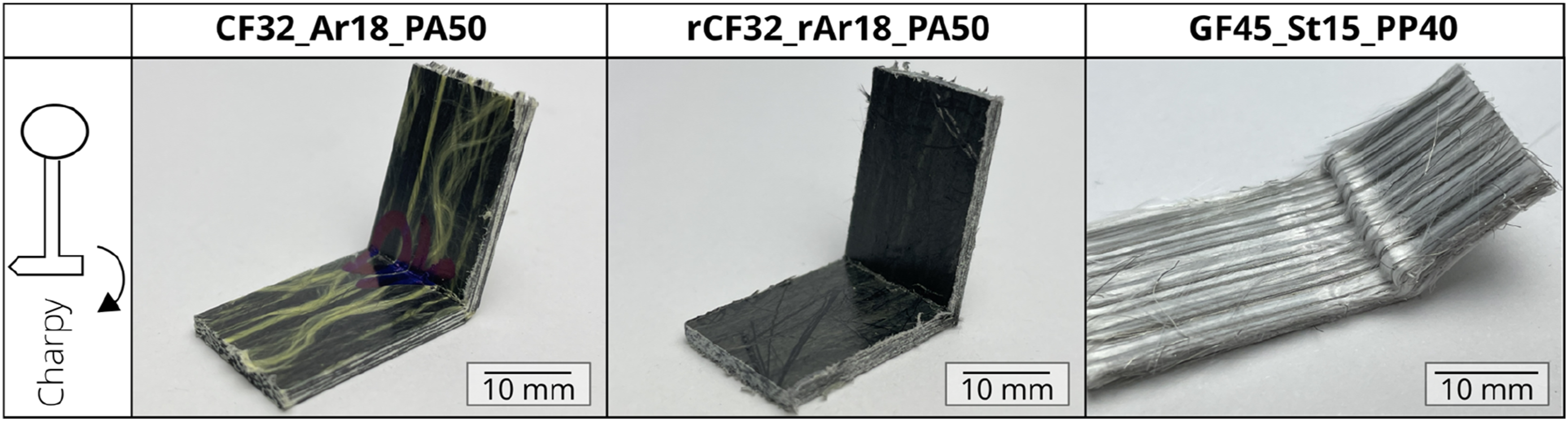
Consequently, Concept 2 exhibited the highest total energy dissipation during impact (3.12 ± 0.37 J), compared to 1.46 ± 0.08 J for Concept 1 and 1.74 ± 0.18 J for Concept 3 (Figure 13(c)).
Similarly, the significantly higher calculated impact strength of Concept 2 (114.97 ± 9.77 kJ/m2) relative to Concept 1 (57.16 ± 2.34 kJ/m2) and Concept 3 (63.12 ± 6.81 kJ/m2) is directly attributable to the ductility provided by metallic fibres and the extensive deformation area within the composite structure.
Overall, these results emphasize the superior impact resistance and energy absorption capabilities of
Tensile tests after impact
The results of the post-impact tensile tests are presented in Figure 15. The maximum force at break measured for each composite group was as follows: Concept 1 (CF32_Ar18_PA50) at 1122.19 ± 201.09 N, Concept 3 (rCF32_rAr18_PA50) at 685.84 ± 281.64 N, and Concept 2 (GF45_StS15_PP40) at 1634.46 ± 297.25 N. Results of tensile tests conducted post-impact, depicting (a) the force versus elongation curves and (b) the force at break for the tested specimens.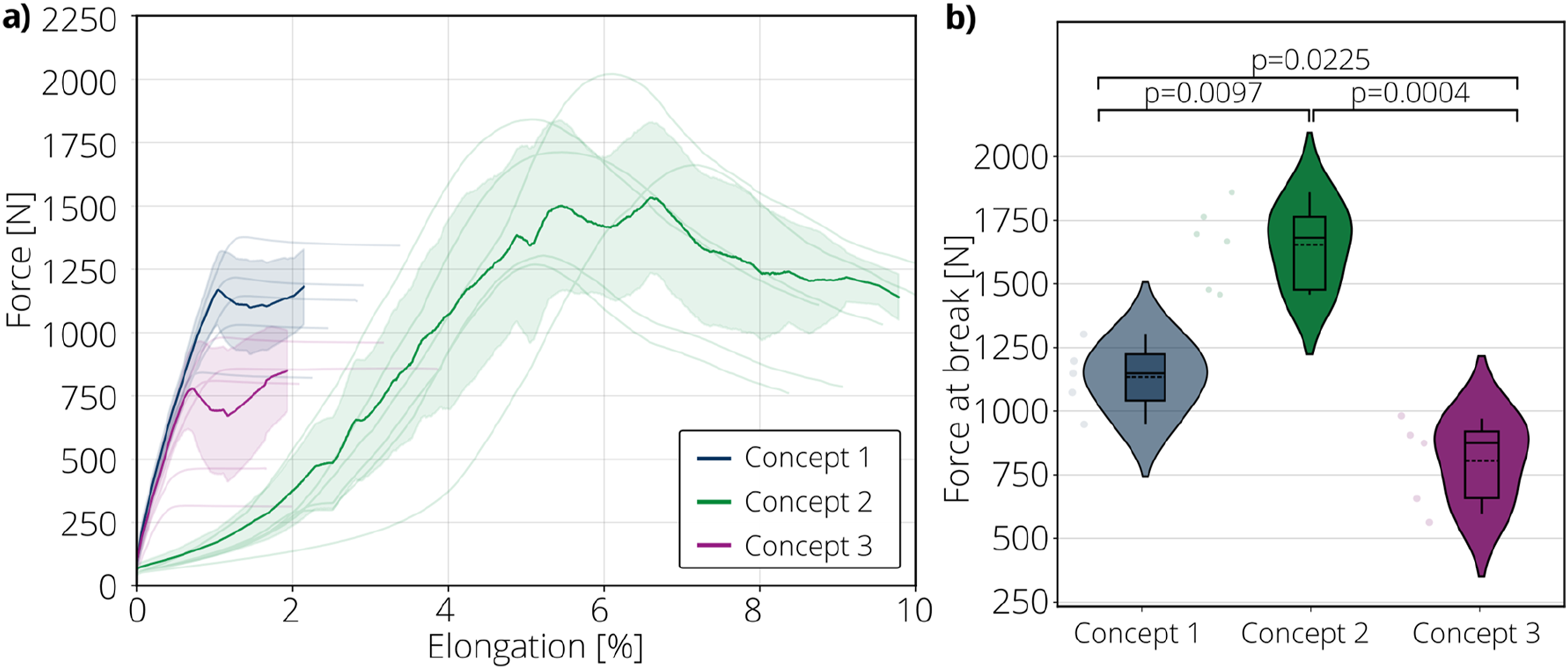
Comparing Concept 1 with Concept 3, the force-elongation curves reveal similar behaviours, but the maximum forces for Concept 3 were consistently lower. Specifically, the residual tensile strength of Concept 1 was found to be approximately 64% greater than Concept 3, a difference primarily attributed to the use of virgin fibres in Concept 1, resulting in a higher proportion of intact fibres within the impact area compared to recycled fibres in Concept 3.
Furthermore, comparing Concepts 1 and 3 with Concept 2, it is evident that Concept 2 exhibits the highest maximum force values, suggesting a greater proportion of intact fibres remaining after impact. Notable differences in the force-elongation profiles were observed; Concept 2 displayed a progressive, nonlinear curve, whereas Concepts 1 and 3 exhibited predominantly linear increases until fracture. Additionally, the elongation at break for Concept 2 (6.08%) was significantly higher compared to Concept 1 (1.38%) and Concept 3 (1.11%). This pronounced elongation correlates with greater fibre deformation during the impact tests, which subsequently aligns the fibres more effectively along the tensile load direction, explaining the progressive elongation behaviour observed.
Figure 16 provides a comparative visual analysis of specimen fracture behaviour following post-impact tensile testing. Concepts 1 and 3 showed comparable fracture characteristics, experiencing complete fracture upon tensile loading post-impact. Conversely, Concept 2 specimens exhibited notably enhanced resistance to fracture, highlighting their superior toughness and residual durability after impact. Such behaviour demonstrates the favourable potential of Concept 2 for applications prioritizing crashworthiness, impact resistance, and energy dissipation capacity. Images of specimens tested in tensile after impact tests.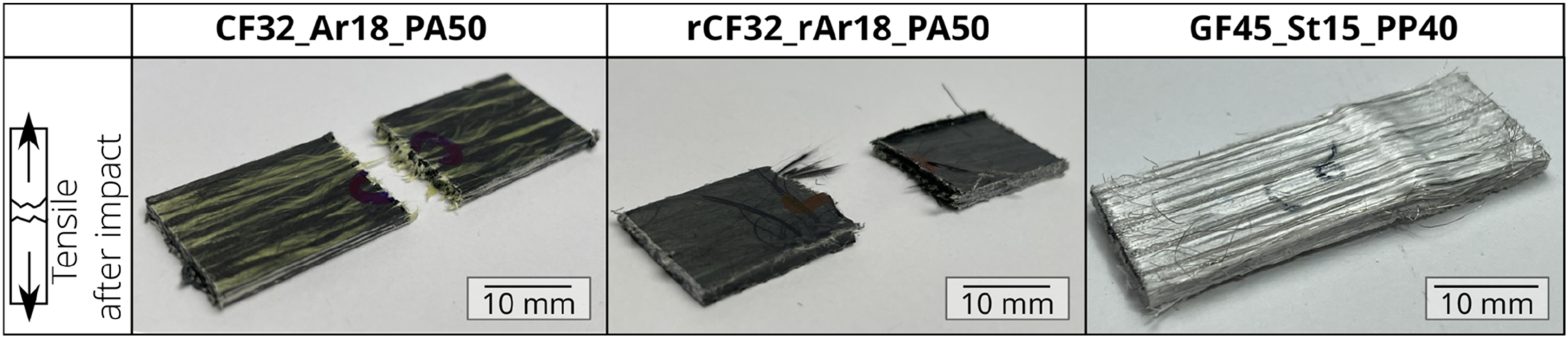
Conclusion
The single-fibre tensile tests revealed significant differences in tensile properties and energy absorption potential across the fibre types studied. Carbon fibres (CF) exhibited the highest tensile strength but relatively low elongation at break, whereas stainless steel (StS) fibres displayed lower tensile strength but exceptional elongation capabilities. The high mechanical work measured for StS fibres indicates superior energy dissipation capacity, highlighting their potential for enhancing damage tolerance in composites requiring robust impact resistance.
Analysis of yarn production parameters identified air jet pressure and overfeed rate as critical influencing factors, with higher air pressure correlating with increased fibre damage and reduced tensile strength. Optimal parameters for air pressure and overfeed were established to achieve maximum tensile strength and yarn uniformity. These optimized settings facilitated the production of hybrid yarns for subsequent composite fabrication, including concepts utilizing both virgin and recycled fibres.
Composite tensile testing showed that the carbon-aramid-based composites (Concepts 1 and 3) exhibited higher tensile strengths compared to the glass-steel composite (Concept 2). However, Concept 2 demonstrated significantly higher elongation at break due to the inherent ductility of the steel fibres, which enhances energy dissipation capacity. This characteristic makes Concept 2 particularly suitable for applications where high impact resistance and flexibility are required.
Fracture surface analysis further underscored distinct mechanical behaviours among composites. Concepts 1 and 3 exhibited predominantly brittle fracture patterns, in contrast to the more ductile fracture behaviour of Concept 2, which showed extensive delamination and many intact fibres post-testing. Although the presence of voids was noted in Concept 2, the enhanced impact resistance is primarily attributed to its fibre architecture and ductility provided by the metallic fibres, rather than void formation itself.
Charpy impact testing confirmed Concept 2’s superior energy absorption capability relative to the carbon-aramid composites. Its combination of ductility and extensive deformation zones due to steel fibre integration provides exceptional crashworthiness and impact performance.
Post-impact tensile tests have shown that Concept 2 retains higher residual tensile strength and elongation than the other composites, reinforcing its suitability for safety-critical applications requiring high energy dissipation and gradual failure modes. Despite its lower inherent tensile strength, its superior toughness and impact resistance make it highly attractive for structures prioritizing energy absorption and failure predictability.
A comparative analysis of the production systems (Concepts 1–3) shows clear advantages and compromise situations. Concepts 1 and 2, utilizing modified air jet texturing processes, offer economic benefits due to higher processing speeds and fewer production steps. Specifically, Concept 2 incorporates steel and glass fibres to increase ductility and mitigate brittle fracture, thus enhancing safety margins. However, the heavier and costlier steel fibres in Concept 2 contrast with the lighter, more affordable aramid fibres in Concept 1, which may be preferable for lightweight applications. Conversely, Concept 3, based on reclaimed fibres from waste, aligns closely with sustainability goals. While currently less economically viable due to the complexity of fibre reclamation, ongoing advancements in recycling technologies promise future improvements in cost-effectiveness and scalability. In summary, Concepts 1 and 2 provide immediate economic and performance benefits, whereas Concept 3 represents a sustainable long-term approach likely to gain competitiveness as recycling methods evolve.
Footnotes
Funding
The author(s) disclosed receipt of the following financial support for the research, authorship, and/or publication of this article: Deutsche Forschungsgemeinschaft; 441549528.
Declaration of conflicting interests
The author(s) declared no potential conflicts of interest with respect to the research, authorship, and/or publication of this article.