
Abstract
With increased use of carbon fibre (CF)-based textile-reinforced thermoplastic composites, the demand of hybrid yarns consisting of carbon filament yarns (CFYs) and thermoplastic filament yarns with improved properties is also high. Hybrid yarn manufacturing using commingling process by means of compressed air shows some distinct advantages over other hybrid yarn manufacturing processes. However, the potential of commingling process for the production of CF-based thermoplastic hybrid yarns is not yet fully explored. In this article, extensive investigations have been carried out for the development of commingled hybrid yarns manufactured from CFY and polyamide 6,6 (PA 6,6) filament yarns with improved adhesion properties between CFY and matrix in composites. Hybrid yarns are manufactured by varying air pressure and keeping overfeeds and delivery speed constant. Moreover, an additional heat treatment on CFY is done online for a better opening of CFY prior to the mixing with PA 6,6 filament yarn. The tensile properties of hybrid yarns as well as different mechanical properties of unidirectional composite, such as tensile, flexural, impact and interlaminar shear strength are investigated. The results show good potential for the development of hybrid yarns produced from CFY and thermoplastic filament yarns with improved adhesion properties for their application in textile-reinforced thermoplastic composites.
Introduction
Carbon fibre (CF)-reinforced composites (CFRCs) composed of endless CF reinforcement combined with a binding matrix have widely been used for load bearing structural components because of their excellent strength, rigidity and damping properties as well as low weight and high resistances to impacting and corrosion. Considering the type of polymer matrix used for volume application, CFRCs are divided into thermoset and thermoplastic composites. Although CFRCs are preferentially manufactured based on a thermoset matrix (more than 75% of all the composites), thermoplastic composites have now been developed due to some distinctive advantages over thermoset composites. 1 The advantages include lower density, unlimited storage of preform, semi-finished products delivered ready for use, thermoformability, a faster processing cycle, no solvent emissions during the processing stage, recyclability and improved shock/impact behaviour. 2 A large range of tough thermoplastic matrix materials is also available. As a result, thermoplastic CFRCs are attracting growing interest from the academic community and industry. 3,4
In order to overcome the problems associated with high viscosity of thermosplast melts, the minimization of mass transfer distance of thermoplast melt in composite is achieved by mixing the reinforcement fibres with thermoplastic fibres in hybrid yarn structures. There are several hybrid yarn manufacturing processes to combine endless carbon filament yarn (CFY) with thermoplastic component in the form of short fibres/filaments or coating such as twisting, powder coating, 5 DREF friction spinning, 6 spreading, 7 stretch breaking 8 and commingling by means of compressed air 9 for the manufacturing of textile-reinforced thermoplastic CFRCs. However, the advantages of the commingled process over other hybrid yarn manufacturing processes include higher productivity, higher flexibility of the manufacturing process, such as the customization of fibre–matrix ratio, and yarn fineness per the requirements. Other advantages are the possibility to combine filament yarns available in the market and homogenous mixing of the components as well as better textile physical properties and textile processability of hybrid yarns. For these reasons, the commingled process is still a front runner for the production of hybrid yarns consisting of CFY and thermoplastic matrix component (e.g. polypropylene, polyester, polyamide (PA) and polyether ether ketone (PEEK)) suitable for a cost effective and rapid production of high-performance thermoplastic composites. The only disadvantage of this process is the damage in the brittle reinforcement component due to air pressure (applied quasi perpendicular to the filament bundles using a commingling nozzle) and requires special care for the processing of high-performance filament yarns such as glass fibre (GF), CF and aramid.
For manufacturing the CF hybrid yarns apart from homogenous mixing and lower damage during hybrid yarn production as well as processability, the surface properties of CF need to be taken into account because properties of polymer matrix and the interaction/compatibility between fibre and matrix play a big role on their adhesion properties and consequently on the long-term durability and performance of the CFRCs. Generally, commercially available CFYs are surface oxidized and then sized to improve the adhesion (between fibre and matrix in composite) as well as the processability. However, the commercially developed sizings are mostly compatible for epoxy-based matrix 10,11 due to the fact that CFRCs are preferentially manufactured based on a thermoset matrix (predominantly epoxy based). This on one hand tends to have negative effect on the adhesion properties between CF and matrix of thermoplastic composites due to the lack of compatibility. 12 On the other hand, it reduces the mixing properties of individual CF filaments and thermoplastic filaments in hybrid yarns.
A large number of research studies have been reported on the influence of process parameters on different GF hybrid yarn properties produced by commingling process as well as on composite properties. 13 –18 However, little information can be found on CFY hybrid yarns manufactured by commingling process using compressed air for the application in thermoplastic composites. In the study by Choi, 19 the improvement of the flexural rigidity (three-point bending) of CFRC with the application of heat on CFY, during hybrid yarn manufacturing (with CFY and PEEK filament yarns), has been reported. However, still there is a lack of understanding on the influence of commingling processing parameters from the perspective of CFY surface properties, microstructure and different mechanical properties of composites. In this article, results of further investigations, especially regarding the influence of additional heat application (during the manufacturing of commingled hybrid yarns) for the improvement of adhesion properties between CFY and polyamide 6,6 (PA 6,6) in the composite, are reported for the first time.
Experimental
Raw materials
CFY (Tenax-E HTA40, Toho Tenax, Japan) and PA 6,6 (Barnet Europe, Germany) are used to produce the hybrid yarns. The characteristics of the components are detailed in Table 1.
Characteristics of CFY and PA 6,6 used for the manufacturing of hybrid yarns.
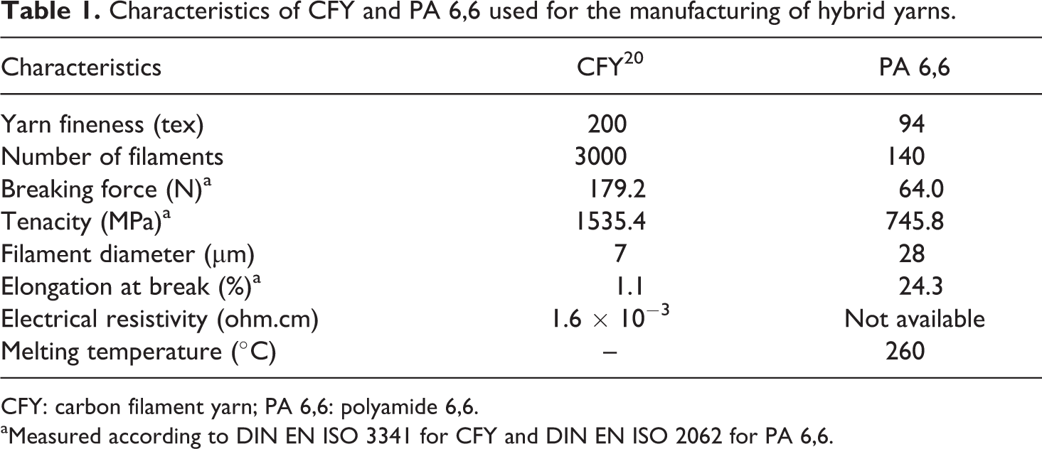
CFY: carbon filament yarn; PA 6,6: polyamide 6,6.
aMeasured according to DIN EN ISO 3341 for CFY and DIN EN ISO 2062 for PA 6,6.
Hybrid yarn manufacturing
A modified air-jet texturing machine (Type RMT-D (Stähle-Eltex GmbH, Germany)) at the Institute of Textile Machinery and High Performance Material Technology (ITM) Dresden (Germany) is used for the production of commingled hybrid yarns consisting of CFY and PA 6,6 filament yarns (see Figure 1). The CFY and PA 6,6 filament yarns are fed by means of separate godet pairs. The mixing of the CFY and PA 6,6 filament yarns is realized aerodynamically using an intermingling nozzle (LD 32.05 (Temco, Germany)).
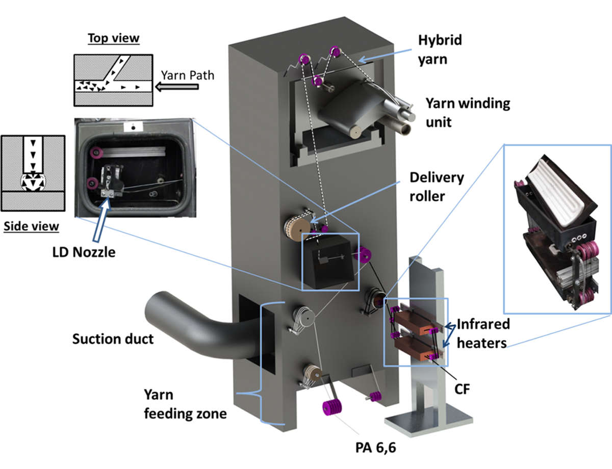
Air texturing machine with IR heaters used for the manufacturing of commingled hybrid yarns consisting of CFY and PA 6,6. IR: infrared; CFY: carbon filament yarn; PA 6,6: polyamide 6,6.
For a homogenous mixing of both the components, the tension in the filaments must be low to expedite the opening of the filaments at the mixing point. This is done by means of an overfeeding of the filaments, keeping the speed of the feeding rollers faster than that of the drawing roller. The overfeed used for CFY and PA 6,6 is 2% and 3.5%, respectively. The hybrid yarns are produced by varying the air pressure from 3.5 bar to 5 bar, keeping the delivery speed (100 m/min) constant.
It is to be mentioned that a minimum air pressure of 3.5 bar is required to produce the hybrid yarns with satisfactory processing quality (i.e. compactness of hybrid yarn and mixing of the components). The theoretical fineness of the hybrid yarns is 301 tex and fibre–matrix volume ratio is 57:43. Furthermore, the CFY is passed through two infrared (IR) heaters (dimension 25 × 62.5 cm2) at 430°C before it is fed to the yarn feeding roller (see Figure 1). The hybrid yarns produced with different processing variables are listed in detail in Table 2.
Process variables and specifications of the manufactured hybrid yarns.
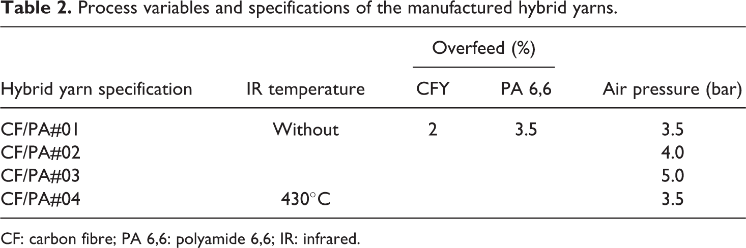
CF: carbon fibre; PA 6,6: polyamide 6,6; IR: infrared.
The effective length of the CFY under IR is 127.5 cm. The aim of using IR heaters is to investigate the effect of heating on the individualization of filaments in the CFY to improve the mixing with the thermoplastic filament in the hybrid yarn and the consequent effect on the composite properties, especially the adhesion between matrix and fibre. It is to be mentioned that trials with different temperatures (>430°C) are also carried out. However, 430°C is found optimum to ensure a proper and smooth running of the hybrid yarn production as CFY breaks frequently at temperatures higher than 430°C with this existing processing and material parameters.
The CF dusts produced during the manufacturing of hybrid yarns are sucked up continuously by a suction duct, which is necessary to avoid environmental pollution as well as any short circuit of other electronic devices due the electro conductivity of CF.
Wettability analysis
In order to characterize the effect of heating on the surface properties of CFY, the wettability of single filament of original CFY, CFY treated at 430°C and PA 6,6 is determined by single-fibre tensiometry and surface energy calculation.
The contact angle (θ) is measured using a modified ‘Wilhelmy balance technique’. For this purpose, a single filament is immersed into the testing liquid with known surface tension σl and from the force F occurring during immersion the contact angle fibres is calculated according to equation (1):
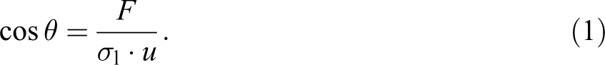
The circumference u is determined by light microscopy. The measurements are carried out at room temperature at 20 ± 2°C. Six individual measurements are taken at randomly chosen filaments to calculate the mean value for each fibre and testing liquid. The total surface energy and its associated polar and dispersive component of the fibres are calculated from the results of the contact angles measured with water and di-iodide methane, according to Owens, Wendt, Rabel and Kaelble method using the equation (2) 21 :

where

From the calculation of surface energy, the thermodynamic work of adhesion (WA) between CFY (original and heat treated) and PA 6,6 matrix is calculated using equation (4) 22 :

where
Analysis of tensile properties of hybrid yarns
For the analysis of tensile properties of manufactured hybrid yarns, tensile tests are carried out according to DIN ISO 3341 standard (length yarn sample: 500 mm; test velocity: 20 mm/min) using a tensile strength testing device Zwick type Z 100 (Zwick GmbH and Co., Germany). Forty measurements are taken for each type of hybrid yarn, and the stress–strain behaviour is evaluated using testXpert® software.
The effect of air pressure and heat treatment on the statistical distribution of hybrid yarn tensile strength is analysed by Weibull distribution through least squares method. The cumulative fracture probability P for the single two-parameter Weibull distribution (based on single risk model) at or below a stress σ is represented by equation (5) 23,24 :
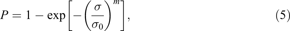
where m and σ0 are the Weibull modulus and the scale parameter, respectively. P is calculated by
However, it was proposed that the distribution should be given by the modified modal Weibull distribution based on multi-risk model, if two or more kinds of strength limiting defect population exist together in brittle material. The P for bimodal Weibull distribution function is given by equation (6), and the Weibull moduli m1 and m2 are calculated 26 :

Preparation of UD thermoplastic composite test specimen
In order to investigate the influence of different process parameters on the mechanical properties of thermoplastic composites manufactured from the hybrid yarns, unidirectional (UD) composite plates are produced. This is done by wrapping the hybrid yarn using a wrapping frame (Industrielle Wickeltechnik (IWT) GmbH, Germany), which is then consolidated by the Laboratory press machine P 300 PV (Dr Collin GmbH, Germany). The consolidation is carried out by a computer-controlled cycle (under vacuum) comprised of a heating step from 30°C to 320°C. The temperature is kept constant at 320°C for 1200 s. A pressure of 5 bar is applied from the beginning and up to the reach of 320°C. This pressure is kept constant for 600 s at 320°C. Then the pressure is increased to 73 bar and finally, the temperature is dropped down to 30°C at 73 bar pressure.
Different test specimens with the dimensions mentioned in Table 3 are cut out of the consolidated composite plates to carry out tensile, flexural, apparent interlaminar shear and Charpy impact tests.
Dimension of test specimen for different tests carried out on UD composites.
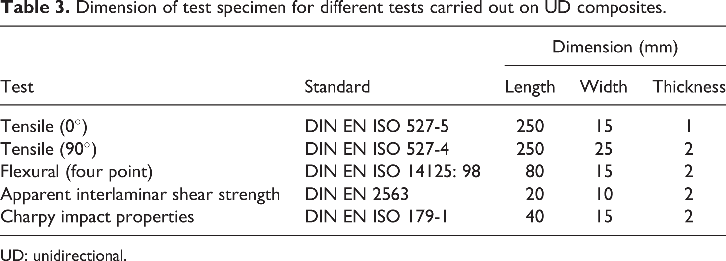
UD: unidirectional.
Analysis of mechanical properties of composites
Testing of the tensile, flexural and apparent interlaminar shear properties of the composite specimen is performed on the testing device Zwick type Z 100 (Zwick GmbH and Co., Germany). The impact tests are carried out on the Charpy-Pendelschlagwerk CEAST 9050 (Instron GmbH, Germany) test device with the aid of a pendulum arm type impact tester based on the principle of Charpy impact test technique.
The four-point loading method is used for testing the flexural strengths of the specimens. The apparent interlaminar shear strength test is done by a three-point loading method. This method consists of the determination of the resistance to delamination under shear forces parallel to the layers of the laminate and provides information about the quality of the fibre–matrix bonding. A minimum of 10 measurements are taken to obtain the average value for each type of test. All the tests are carried out at the ITM Dresden. The test standards are detailed in Table 3.
Results and discussion
Wettability analysis
From the results of contact angle measurements and calculated surface energy summarized in Table 4, a slight change in wetting properties due to the application of heat on CFY can be revealed. The contact angle of CFY in water (
Contact angle and surface energy values of different fibres used in the production of hybrid yarns.
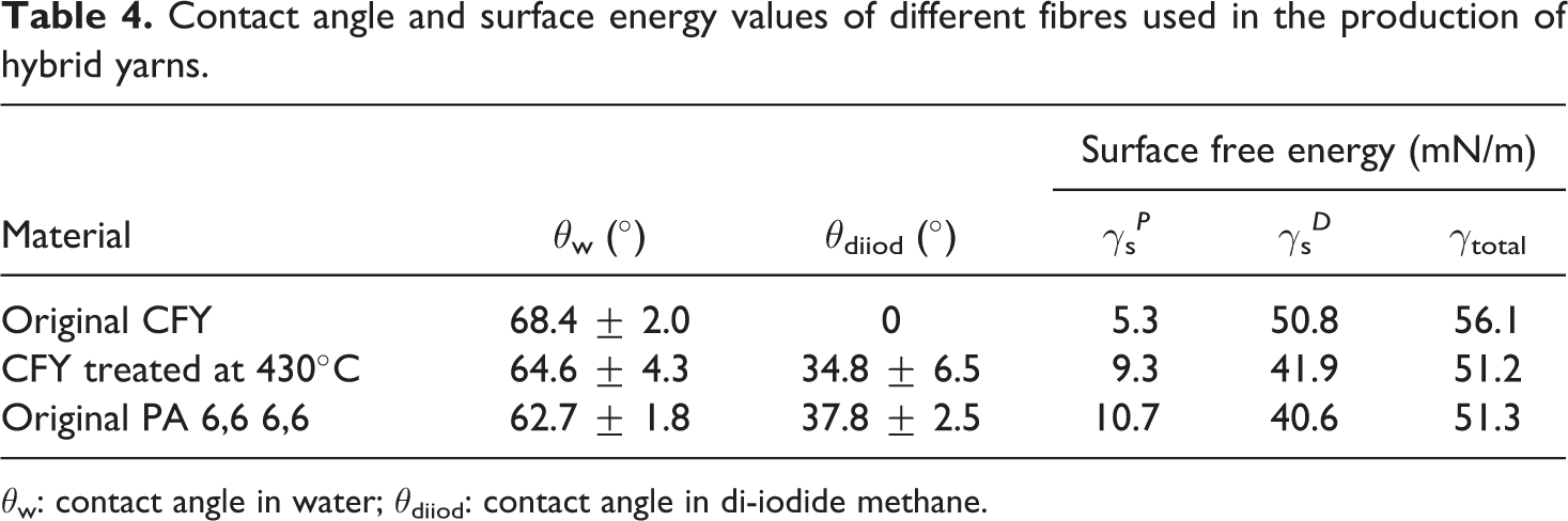
θw: contact angle in water; θdii od: contact angle in di-iodide methane.
It is interesting to find that the surface energy, polar and dispersive part of the heat-treated CFY are almost similar to those of PA 6,6 (see Table 4). This indicates a better compatibility of both the components in composite. 27 However, from the calculation according to equation (3), it is found that the WA of original CFY (105.1 mN/m) is higher than that of heat-treated CFY (102.4 mN/m) with PA 6,6 matrix.
Tensile properties of hybrid yarns
A detailed illustration of the results of tensile tests of hybrid yarns and respective Weibull cumulative distribution function are shown in Figure 2. From the typical force–elongation curves of the original CFY and the manufactured hybrid yarns illustrated in Figure 2(a), it can be seen that the hybrid yarn strength decreases with the increase of air pressure significantly, as expected. A higher air pressure leads to higher damage in the CFY, since the CF is sensitive to shear forces. The average breaking force of hybrid yarns manufactured with 3.5, 4 and 5 bar is found 33%, 49% and 68% less than that of original CFY, respectively.
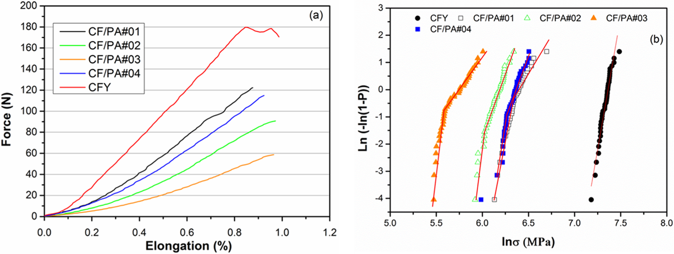
(a) Typical force–elongation curves of the original CFY and manufactured hybrid yarns and (b) Weibull plots of the tensile strength of hybrid yarns (by bimodal cumulative distribution function) and original CFY (by single-modal Weibull cumulative distribution function). CFY: carbon filament yarn.
Furthermore, from the force–elongation curves, a decrease of modulus in hybrid yarns compared to the original CFY can be observed, which is the result of the hybrid yarn structure produced by an overfeed of 2% for CFY and 3.5% for PA 6,6. Due to the overfeed of CFY during the commingling process, the CFYs in the hybrid yarn structure are not as stretched as in the original CFY. Therefore, the initial slope of the force–elongation curves determining the modulus of hybrid yarns is considerably lower compared to that of the original CFY. Furthermore, the damage of the CFY in the hybrid yarn structures with increased air pressure also causes the reduction of modulus.
Furthermore, the breaking force of the hybrid yarn manufactured from heat-treated CFY is 36% less than that of original CFY. This reduction in tensile strength can be attributed to the additional damage that occurs during the heat treatment, due to more accumulation of fibres onto the yarn-guiding rollers in the IR set-up, because CFY is susceptive to oxidation at higher temperature as well to the deflection in traverse direction.
From Figure 2(b), it can be seen that the strength values of original CFY fit well to a straight line; however, the data of hybrid yarns do not suitably fit to the straight line and are therefore deviated from the single-modal Weibull distribution. The results of hybrid yarns can be explained by bimodal Weibull distribution and are summarized in Table 5.
Weibull modulus and the scale parameters of the manufactured hybrid yarns.
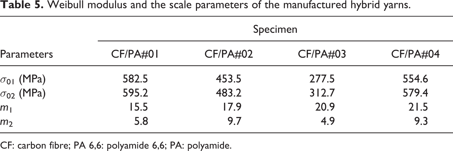
CF: carbon fibre; PA 6,6: polyamide 6,6; PA: polyamide.
With increased air pressure, the Weibull plots of the manufactured hybrid yarns shift to left and the scale parameters decrease (see Figure 2(b)), indicating a lower characteristic strength as already mentioned due to the damage in CFY component. From Table 5, it can be seen that the Weibull modulus increases with the increase of air pressure (except m2 for CF/PA#03), indicating a narrow strength distribution. The same tendency can also be found in case of CF/PA#04 compared to CF/PA#01. This is because of the homogenization of tensile properties due to increased air pressure or better mixing due to desizing effect.
Figure 3 illustrates the cross-sectional images of the hybrid yarns produced for the investigations. The cross-sectional images generally show some degree of PA 6,6 filaments within the carbon filaments. From the subjective evaluation and previous experience, it can be revealed that generally with higher air pressure, the mixing of the both components as well as compactness of hybrid yarns increases. The difference in the mixing of both the components in the hybrid yarn cross section due to air pressure can be seen more clearly by comparing CF/PA#01 and CF/PA#02 with CF/PA#03. By comparing CF/PA#01 and CF/PA#04, a slightly better mixing of the components can be revealed in CF/PA#04, due to better individualization of single filaments, as a result of desizing effect due to heat treatment.
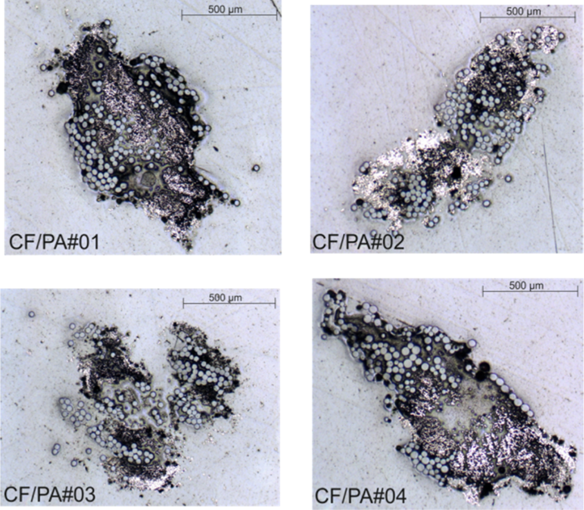
Cross-sectional images of hybrid yarns.
Mechanical properties of UD composite
From the results of tensile tests of UD composites produced from different hybrid yarns and carried out in fibre (0°) and in traverse direction (90°) (illustrated in Figure 4), the indication of damages as well as orientation of CFY reinforcement and the adhesion between matrix and CFY can be found, respectively.
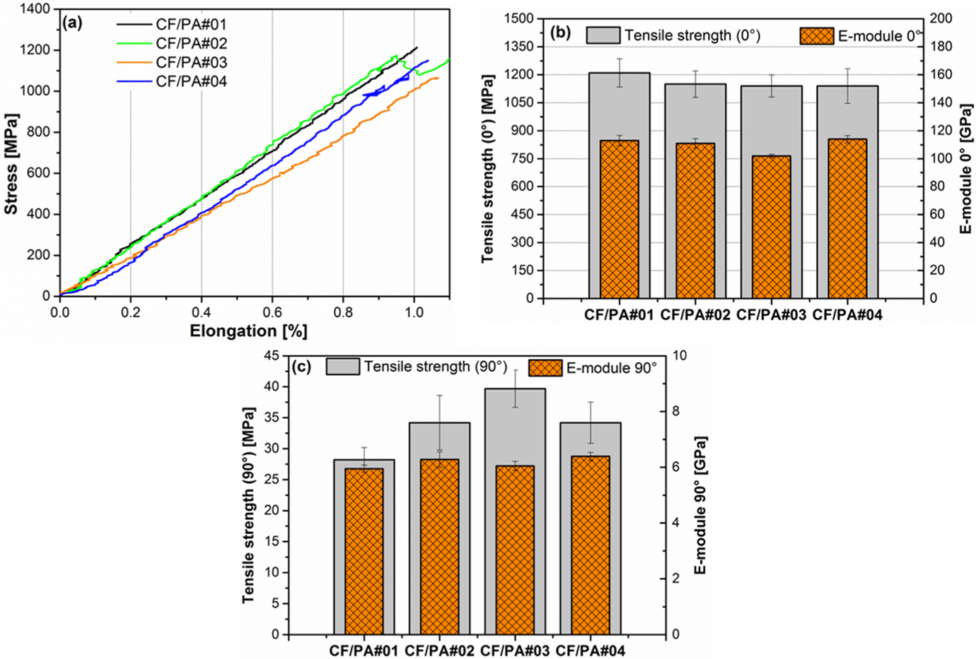
Results of tensile tests of UD composites produced from hybrid yarns: (a) typical stress strain diagram (in 0° direction), (b) average tensile strength and E-module values (in 0° direction) and (c) average tensile strength and E-module values (in 90° direction). UD: unidirectional.
From Figure 4(a) and (b), it can be seen that there is a tendency of slightly reduced tensile strength of UD composite (in 0°) with the increase of air pressure. However, this decrease in tensile strength is insignificant compared to that found in hybrid yarn. It indicates that the damage in the CFY due to compressed air is compensated well as a result of a good and homogenous impregnation of the CFY by the surrounding matrix in the composite (see Figure 5). The composite produced with CF/PA#04 also shows slightly less tensile strength than that of CF/PA#01, caused by the filament damage because of IR heaters, as mentioned already. The typical stress–elongation curves observed from the tensile strength (in 0° direction) of composites are illustrated in Figure 4(a).
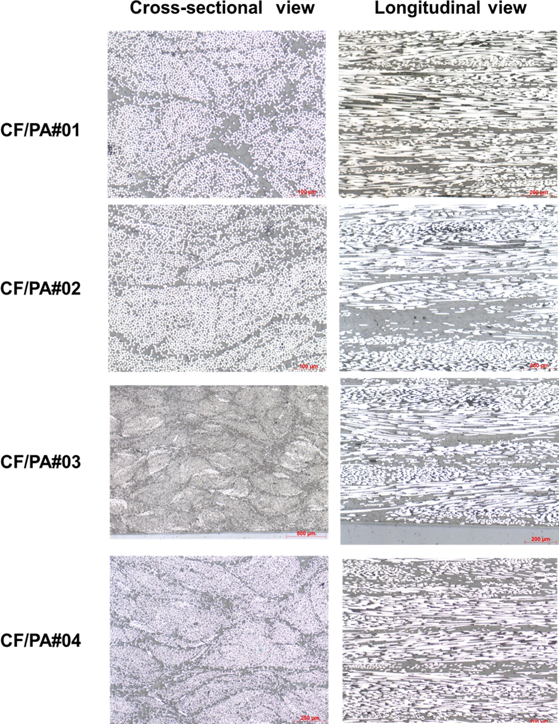
Cross-sectional (left) and longitudinal (right) images of UD composites produced from hybrid yarns made from CFY and PA 6,6 filament yarns. UD: unidirectional; CFY: carbon filament yarn; PA 6,6: polyamide 6,6.
The results of tensile strength of UD composite in 90° are illustrated in Figure 4(c). By comparing CF/PA#01, CF/PA#02 and CF/PA#03, it can be seen that the tensile strength of the composite in 90° direction increases significantly with increased air pressure. Due to higher compressed air pressure, the mixing of the both components in the hybrid yarn cross-section also increases. However, the increase in mixing is accompanied at the same time by less orientation of the CFY along the yarn length. Because of these both effects, the tensile strength of composites in 90° direction increases with increased air pressure. By comparing the tensile strength (in 90°) of CF/PA#01 and CF/PA#04, a significant increase in tensile strength can be revealed, which indicates a higher adhesion between matrix and reinforcement components. This can be attributed on one hand to the higher mixing of the both components in the hybrid yarn due to better individualization of CFY filaments and on the other hand to better compatibility of PA 6,6 and heat-treated CFY (as found from the measurement of surface properties). It is to be mentioned that though the work of adhesion of heat-treated CFY and PA 6,6 filament is found slightly lower than that of original CFY, the adhesion in composite is found significantly higher. This is because the adhesion between fibre and matrix is also influenced by the mechanical interlocking due to surface roughening of fibres, which is not taken into consideration.27
The results of flexural strength tests (see Figure 6(a) and (b)) show also the same tendency as also found in tensile strength test in 0° direction. The flexural strength of CF/PA#02 and CF/PA#04 is slightly lower than that of CF/PA#01. However, the flexural strength of CF/PA#03 is significantly low compared to the other specimen. The impact strength tests reflect the effect of fibre damage due to air pressure or heat treatment and impact on strength prominently (see Figure 6(c)). This can be attributed to the less resistance of CF to the force acting in traverse direction. As additional damages already exist in the CFY reinforcement due to air pressure/heat treatment, the impact strength is found significantly lower in composites manufactured both with increased air pressure and heat treatment. Furthermore, from the typical force and deformation curves during impact test of UD composites (see Figure 6(d)), the effect of air pressure and heat treatment on the impact properties of composites can be clearly seen. The deformation of CF/PA#03 and CF/PA#04 is considerably lower compared to that of CF/PA#01 and CF/PA#02, indicating more brittleness. It also indicates that higher mixing of both the components in the hybrid yarn as a result of higher air pressure causes higher adhesion between matrix and fibre (by comparing CF/PA#01, CF/PA#02 and CF/PA#03). Similarly, due to better compatibility and higher mixing of both the components as a result of heat treatment on CFY (by comparing CF/PA#01 with CF/PA#04), the adhesion between fibre and matrix increases. Consequently, the composites become more brittle with increase of air pressure and application of additional heat treatment. Generally, a brittle nature of failure mode can be observed during the flexural and impact tests for all types of hybrid yarns produced for the investigations. In Figure 7, the specimens after flexural and impact tests are shown exemplarily in case of CF/PA#01.
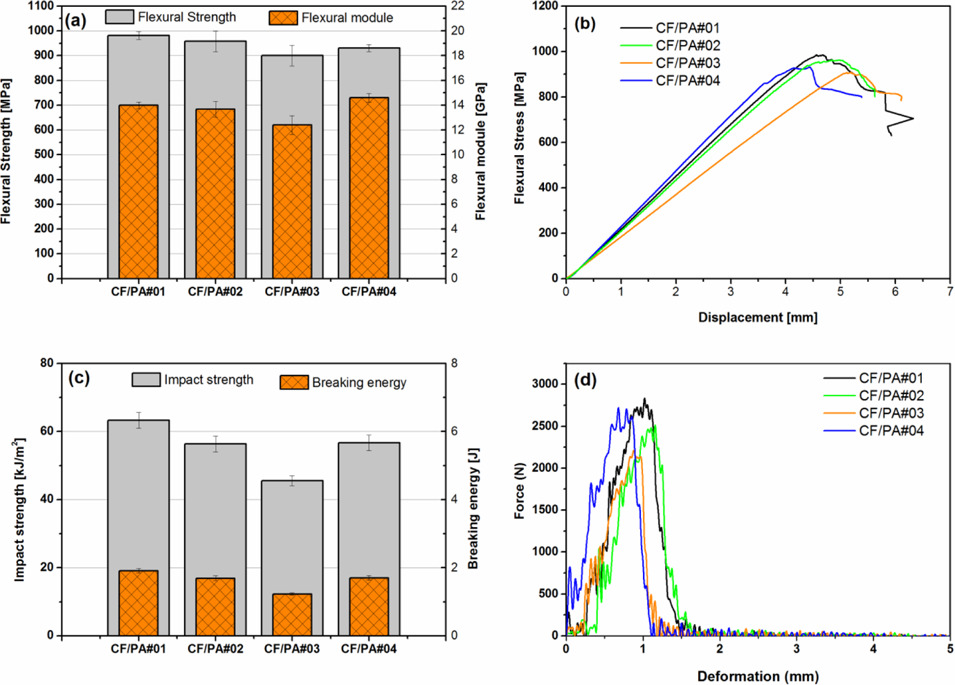
(a) Average flexural strength and module, (b) typical stress and displacement curves of flexural tests, (c) average impact strength and breaking energy and (d) typical force and deformation curves during impact test of the UD composites produced from commingled hybrid yarns. UD: unidirectional.
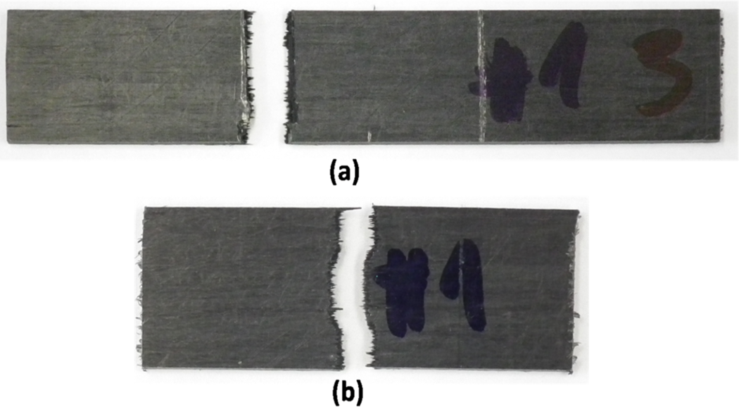
Specimen after flexural (a) and impact (b) test in case of CF/PA#01. CF: carbon filament; PA: polyamide.
The apparent interlaminar shear strength test illustrated in Figure 8 reflects also the influence of mixing and/or better compatibility of heat-treated CFY and PA 6,6 as found in tensile strength of composites in 90° direction. Interestingly, the highest apparent interlaminar shear strength is found in composite produced from heat-treated CFY. With application of additional heat treatment, the apparent interlaminar shear strength can be increased by 9%.
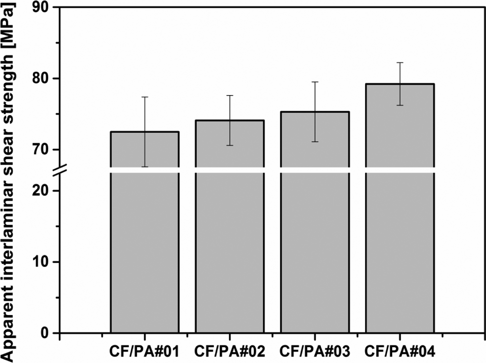
Apparent interlaminar shear strength of UD composites produced from commingled hybrid yarns. UD: unidirectional.
Conclusion
The main aim of this study was to acquire better understanding on the influence of different process parameters of commingling hybrid yarn manufacturing on the adhesion properties between fibre and matrix in CFRC composites. Furthermore, the influence of the process parameters on the composites properties such as tensile (in 0° and 90° direction), flexural (four-point loading), interlaminar shear and impact strength is also investigated. For this purpose, different commingled hybrid yarns are manufactured from CFY and PA 6,6 filament yarns by varying air pressure and the online application of additional heat treatment at 430°C on CFY. In order to find the relationship between surface properties of CFY as a result of heat treatment, the wettability of single filament of original CFY, heat-treated CFY and PA 6,6 is determined by single-fibre tensiometry and surface energy calculation.
The results of composites show that the damage in CFY due to air pressure during hybrid yarn manufacturing seems to be compensated in composite due to bridging effect, as a result of good impregnation of CFY by the surrounding matrix. A slight decrease in tensile (in 0°) as well as in flexural strength is found in case of change of air pressure from 3.5 bar to 4 bar and heat treatment. However, the impact strength decreases as well as the brittleness of composites increases significantly with the increase of air pressure (from 3.5 bar to 5 bar) and heat treatment.
An important result of the investigations is the significant increase of tensile strength (in 90°) and apparent interlaminar shear strength achieved by heat treatment of CFY, indicating a higher adhesion between fibre and matrix in composites. The additional heat treatment of CFY facilitates the better opening of the CFY to produce a homogenous hybrid yarn. At the same time, the heat-treated CFY shows wetting properties similar to those of PA 6,6 matrix filament, offering a better compatibility in composite. Both these effects contribute to the better adhesion of CFY and matrix in composites. However, in order to differentiate the effect of additional heat treatment on the filament opening and better compatibility of CFY with thermoplastic matrix due to the desizing effect, further investigations are necessary.
In essence, the investigations show the potential of the application of heat to improve the mixing and the adhesion properties between matrix and CFY. A lower tensile, bending and impact strength give the indication that there are some damages due to the application of heat, which still can be improved by the modification of IR set–up, for example, by reducing the number of deflection points and increasing the radius of deflection rollers.
Footnotes
Acknowledgement
This article presents a portion of the results from the research project IGF-477 ZBR at the Technische Universität Dresden, Germany. The authors are grateful for the above-mentioned financial support.
Declaration of Conflicting Interests
The author(s) declared no potential conflicts of interest with respect to the research, authorship, and/or publication of this article.
Funding
The author(s) disclosed receipt of the following financial support for the research, authorship, and/or publication of this article: The authors received financial support for the research from the research project IGF-477 ZBR.