
Abstract
Multi-tooth milling cutters have the advantages of minimal surface damages and low cutting forces and are widely used in composite materials milling such as carbon fiber and wood. Cortical bone is a composite biomaterial similar to carbon fiber and wood; however, the cutting performance of multi-tooth milling cutters on bone cutting is unclear. Here, this paper proposes a multi-tooth milling cutter longitudinal torsional ultrasonic vibration assisted milling (LTVUM) method for cortical bone low damage cutting. The cutting performance of sinusoidal and corn edge cutters for cortical bone LTVUM was studied, and its material removal mechanisms were also established. The results indicated that the multi-tooth milling cutter has a smaller average cutting force, and suppressing the chip burrs and tearing damages. Compared to straight edge cutter, the resultant cutting forces of sinusoidal and corn edge cutters are decreased by 52.58%–61.01% and 45.60%−65.96%. The reason is that the secondary cutting edge of multi-tooth cutter can participate in cutting, reducing the tool squeeze interference. This work provides experimental guidance for the application of multi-tooth milling cutters LTVUM in bone cutting.
Keywords
Introduction
Cortical bone is a composite biomaterial similar to carbon fiber and wood. Bone cutting is a usual procedure in medical surgery, and the high quality of bone cutting helps to improve the accuracy and safety of surgery, 1 thereby accelerating the postoperative recovery speed of patients. The cutting behaviors of cortical bone are often affected by its material properties and cutting parameters (e.g., viscoelasticity, anisotropic structure; cutting speed depths of cut).2,3 The bone cutter design and its cutting parameters influence on tissue injury and healing still need research. 4 Bone milling is an efficient surgical operation method in knee joint replacement, ontological maxillofacial, and spinal surgeries.5,6 Cortical bone cutting is prone to brittle crack propagation and large block collapse, which cause surface and subsurface damage to bone, decreasing surgical quality and seriously affecting postoperative recovery. Multi-tooth milling cutters have the advantages of minimal cutting damage, low cutting force, and suppressing burr in the machining of carbon fiber and wood materials.7–9 For example, the carbon fiber composite parts are machined using multi-tooth milling cutters to effectively reduce milling damages, and achieve high accuracy and surface quality, which applied in in aircraft, aerospace, automotive, and sports equipment. 10 Reasonable multi-tooth milling cutters and ultrasonic vibration cutting method are significant ways to decrease bone milling forces and damages. Therefore, Studying the bone cutting performance is crucial for the application of multi-tooth milling cutters in bone ultrasonic vibration assisted cutting.
For difficult-to-cut material cutting, vibration cutting method are common processing strategies. 11 Ultrasonic vibration cutting is a periodic cutting approach with high frequency which applies uses external vibration generated using an ultrasonic setup.12,13 Ultrasonic vibration cutting generates separation cutting which improves chip breakability, reduces surface roughness.14,15 For bone cutting, ultrasonic vibration cutting technology is also a significant approach to reduce its cutting forces and damages. The ultrasonic vibration in bone cutting induces a high instantaneous energy release rate exceeding the material fracture energy release rate. 16 Cracks directly penetrate the bone matrix rather than deviating from the cement line, changing the direction of crack propagation and reducing the correlation between cracks and microstructure.17–20 The chip morphology and crack growth of bone cutting are studied to reveal the mechanisms of bone material damage.21,22 Bone milling is an efficient method for removing bone materials, and its cutting forces and temperature are studied using experimental and numerical simulation methods.23–25 The ultrasonic vibration milling and drilling widely used in machining of bone, carbon fiber, Cf/SiC composites, and metal materials.26–28 The bone longitudinal torsional ultrasonic vibration assisted milling (LTVUM) can enhance cutting surface quality, reduce cutting force and alter the shear mode.29,30 Furthermore, the bone LTVUM reduces the effects of bone anisotropy and cutting speed, while enhancing the impacts of feed rate. 29 Rinck et al.31,32 found that the Ti-6Al-4V of LTVUM significantly reduces cutting force, improves cutting surface smoothness, and it has a better cutting performance compared to longitudinal assisted milling. Besides, Niu et al. 33 investigated the tool edge trajectory and cutting force of LTVUM, and reported that the cutting forces of the x and y directions decreased by 24.8% and 29.9%, respectively. Zhang et al. 34 studied the cutting force coefficient for carbon fiber LTVUM considering the effects of fiber direction, and reported that the milling stability was best at the fiber direction of 45°. Sun et al. 35 built a dynamic model considering the influence of velocity angle generated by longitudinal ultrasonic vibration on dynamic cutting thickness, and found that the stable region of ultrasonic cutting was 133% higher than that of conventional milling. Wu et al. 30 reported that the high-frequency intermittent cutting effect caused by spindle speed and helix angle, and ultrasonic amplitude is the main reason for cutting force. In addition, bone low-frequency vibration cutting has also been studied to improve chip morphology, reduce cutting force and brittle crack damage.36–38
Multi-tooth milling cutters have the advantage of low damage in the machining of composite materials such as wood and carbon fiber. Multi-tooth milling cutters can reduce milling forces and delamination, and improve system stability in milling of Cf/SiC and CFRP composites.8,39 The multi-tooth shapes of milling cutter have significant impacts on its cutting force, surface roughness and delamination damage. Prakash et al. 40 reported both pyramid and trapezoidal multi-tooth milling tools can effectively suppress surface delamination damage, and the trapezoidal tools presented low surface roughness and cutting force. Bari et al. 41 studied cutting force of circular and trapezoidal serrated milling cutters and reported that the cutting forces of the circular cutter are smaller than that of the trapezoidal cutter. Tehranizadeha et al.42,43 investigated the sinusoidal, trapezoidal, and circular serrated milling cutters to reduce cutting forces, and the optimal parameters of serrated waves of tooth profiles were obtained through genetic algorithms. Dombovar et al. 44 reported that sinusoidal sawtooth milling cutters significantly improved the milling stability of the system, achieving efficient machining of titanium alloys and nickel alloys with small cutting forces and high cutting depths. Gou et al. 45 found that the sinusoidal serrated milling cutter had small cutting forces and built a cutting force predictive model with variable tooth pitches and helix angles. Grabowski et al. 46 established a static chip thickness model for serrated end mills and obtained each cutting edge delay time at different positions. Additionally, the rake angle of the cutter directly affects the bone cutting performance. Wang et al. 47 studied bone orthogonal cutting at small cutting depths (5–20 μm) and found that the negative rake angle will cause extrude on bone, and obvious burrs occurred. Zawadzki et al. 48 studied the effects of rake angle and cutting depth on cortical bone cutting performance and reported the cutting force at negative rake angle is greater than that at positive rake angle.
The above researches indicated that multi-tooth milling cutters can diminish cutting force, and suppress tearing damage in composite materials milling. The cortical bone is similar to carbon fiber and wood, which presents anisotropic and brittle characteristics.24,49 Thus, multi-tooth milling cutters have the potential to be used for surgical bone cutting to reduce cutting damage. Additionally, bone ultrasonic vibration assisted cutting can diminish cutting temperature and force,36,50,51 reduce crack propagation damage, and improve surface morphology. 16 In addition, multi-tooth cutting tools ultrasonic vibration assisted cutting also provide new ideas for efficient and low damage bone cutting. However, the application of multi-tooth cutting tools in medical surgical bone cutting has not been reported, and the bone cutting performance of multi-tooth milling cutters in LTVUM are still unclear.
Thus, this paper proposes a cutting method for bone multi-tooth milling cutter in LTVUM to reduce damage. The cutting performances of bone LTVUM for multi-tooth cutter were first elucidated. The ultrasonic vibration assisted milling of bone tissue with multi-tooth milling cutters at different feed rates was studied, revealing the interference mechanism of material removal with different multi-tooth milling cutters under LTVUM. The cutting mechanism of multi-tooth milling was studied through bone cutting experiments, and the material removal mechanisms of multi-tooth cutters under ultrasonic action were analyzed. Reasonable geometric structure of multi-tooth milling cutters under LTVUM conditions was clarified. This work provides experimental guidance for the application of multi-tooth milling cutters LTVUM in bone cutting.
Kinematic analysis of bone multi-tooth cutter ultrasonic vibration milling
Multi-tooth cutters
To reveal the bone cutting performance of multi-tooth milling cutter, the two commonly used sinusoidal edge and corn edge cutters milling were investigated. The different multi-tooth milling cemented carbide cutters with a diameter of 3 mm are exhibited in Figure 1. For the straight edge, sinusoidal edge and corn milling cutters, the numbers of cutting edge are 3, 3, and 8, the helix angles are 45°, 30°, and 18°, respectively, the peak to peak values of multi-tooth are 0, 0.18, and 0.28 mm, and the micro tooth pitch is 0, 1, and 2 mm, respectively. The micro teeth of the cutting tool are periodically distributed along the helix direction of cutting edge. The multi-tooth on different cutters have a staggered arrangement of phase differences. The sinusoidal edge cutter presents sinusoidal cutting edge, and the corn edge cutter shows trapezoidal cutting edge. The variation of the local radius of each cutting edge with height z is expressed as: Multi-tooth milling cutters.


The cutting edges of multi-tooth cutters are not continuous, and its radius of cutters vary periodically. The sawtooth wave function can be expressed as:

Kinematic analysis
Each multi-tooth includes upper and down cutting edges, corresponding to the upper and down flank surfaces are exhibited in Figure 2. To clarify the cutting state of main edge for multi-tooth cutter, the kinematic analysis of the cutter is conducted. The static cutting thickness can be obtained according to tool motion trajectory, and it determines the cutting state of current edge point. Assuming at time t = 0, the tool tip of one multi-tooth tool is located on the Y-axis of the tool’s floating coordinate system. The tool feed motion is along the X-axis direction of the workpiece coordinate system. Therefore, the instantaneous position of point P on the j-edge of the tool end in bone LTVUM is expressed as: Cutting edge trajectory and geometric characteristics of multi-tooth milling cutters. (a) Milling processing of multi-tooth cutter, (b) Cutter cutting edge trajectory, (c) Multi-tooth milling cutter, (d) Micro teeth interfere with bone.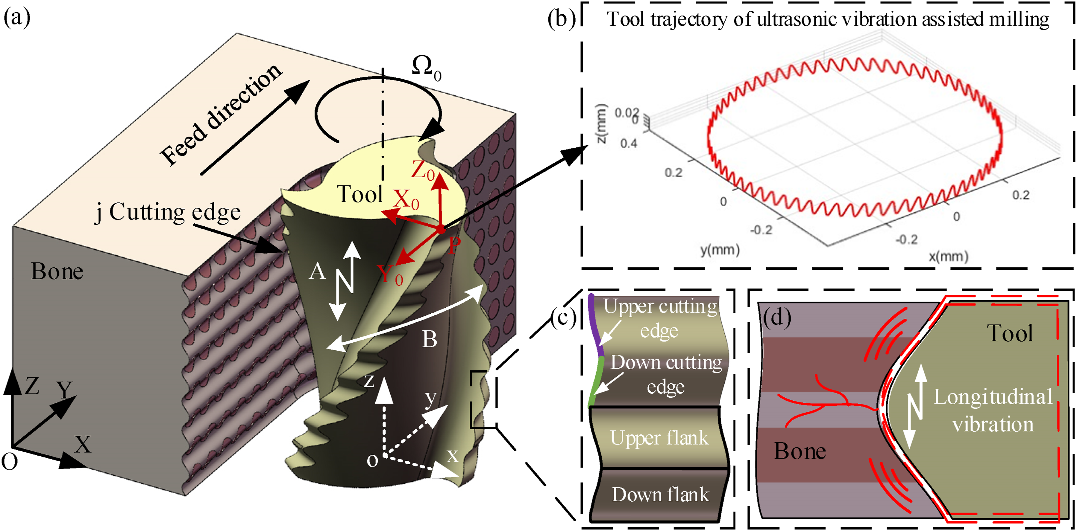


Experimental details
The microstructure and physical characteristics of bovine bone are similar to human bone.
52
The experimental bone tissue sample is the outer cortical bone extracted from the fresh mid femur. The experimental setups for bone ultrasonic vibration cutting are presented in Figure 3. The cutting experimental was conducted on a Siemens 840D CNC machining center, and an ultrasonic vibration device was adopted (Tsingding, China), and the integrated tool holder structure can be clamped on the machine tool spindle for ultrasonic bone milling experiments on bovine cortical bone (Figure 3(a)). The ultrasonic vibration amplitude was obtained by a laser displacement sensor (Keyence, LK-H008, Japan). A rectangular bone specimen with dimensions of 20 × 10 × 4 mm was machined by a milling cutter (Figure 3(c)). The processed bone tissue samples were immediately immersed in physiological saline and stored in the refrigerator. Experimental setups for bone ultrasonic vibration cutting.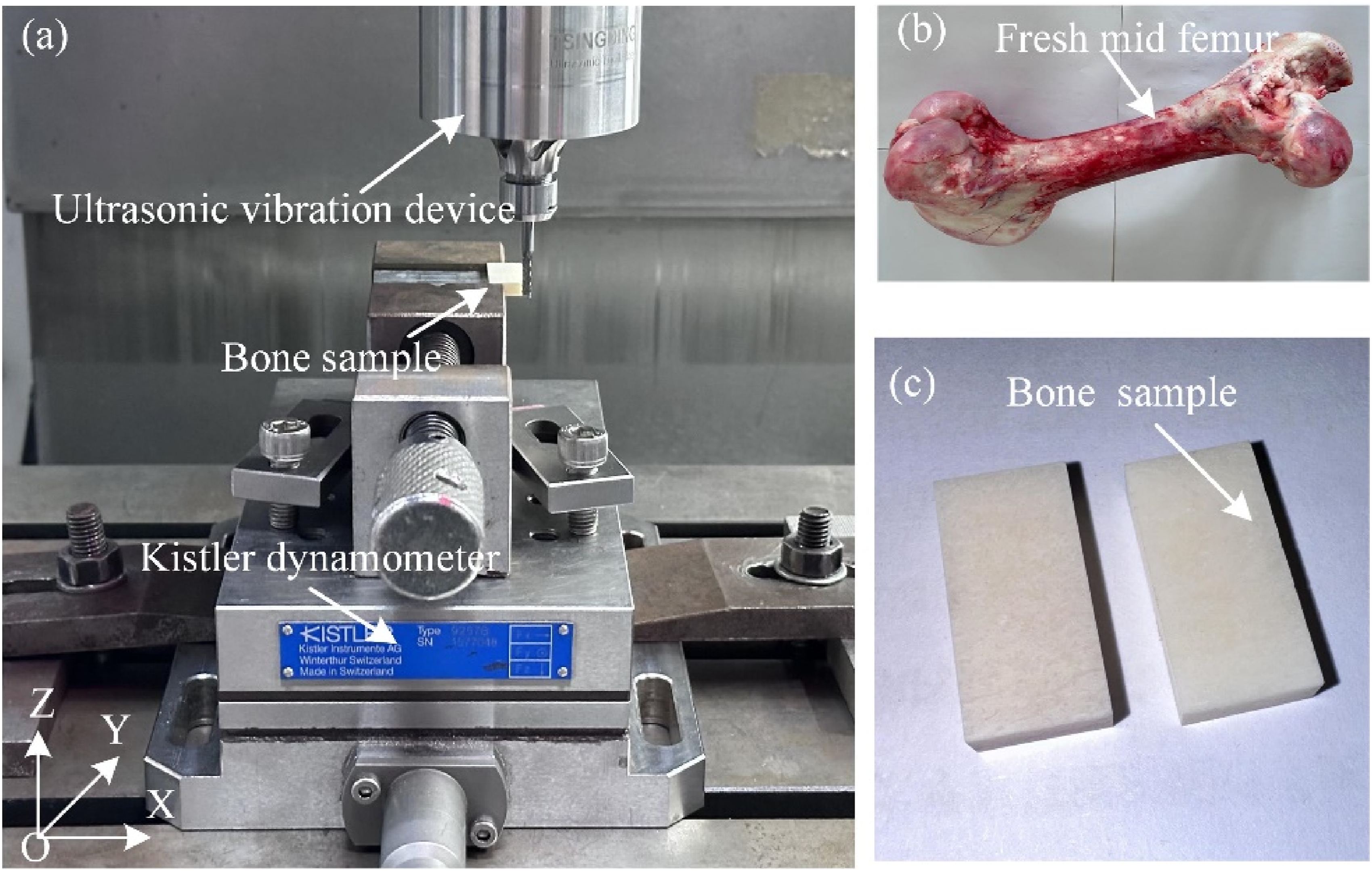
The bone tissue sample was melted and side milling flat using a milling cutter before the experiment (Figure 3(b)). The bone tissue sample was clamped using a jig, and the jig was fixed on the three-axis force sensor. The experiment was side-milling along the Y direction of the workpiece coordinate system, with a radial immersion ratio of 0.6, and the feed direction of the tool was along the transverse direction of bone osteon. Considering that excessive amplitude can cause temperature rise, leading to bone tissue necrosis and nerve damage, 53 the longitudinal amplitude and torsional amplitude are selected 2 μm and 0.001 rad, respectively. The vibration frequency of cutting tools is closely related to its geometric structure. When the frequency is 22.5 kHz, all three types of cutting tools can reach the resonant frequency. The ultrasonic vibration frequency is 22.5 kHz and the phase of longitudinal and torsional vibrations is π. For bone milling, a high feed rate may cause significant brittle fracture and surface damage. Hence, the effect of feed rate on average cutting forces was researched. According to the cutting parameters of orthopedic surgery,25,52 the bone milling parameters for bone tissue are usually selected as spindle speed of 1000–3000 r/min and feed rate of 100–300 mm/min. Thus, the experimental milling parameters were spindle speed of 2500 r/min and feed rates of 150, 200, 250, and 300 mm/min. To ensure the reproducibility of experimental results, each set of parameter experiments were repeated three times. The bone tissue milling forces of Fx, Fy, and Fz were obtained using a Kistler piezoelectric dynamometer (9257B). The cutting forces were collected through NI acquisition card with a sampling frequency of 51.2 kHz (Figure 3(a)). The cutting surface three-dimensional morphologies were measured by a 3D measuring laser microscope (Olympus, OLS4100, Japan). The cutting chip morphology and surface morphology were observed by a scanning electron microscope (SEM, FEI, Quanta 200, America).
Results and discussion
Cutting forces
The bone average cutting forces of different milling cutter are exhibited in Figure 4. With the increase of feed rate, the average cutting force presented an approximately linear growth trend. The resultant cutting forces of sinusoidal and corn edge cutters are significantly lower than that of straight edge. The resultant cutting forces of sinusoidal and corn edge cutters are decreased by 52.58%–61.01% and 45.60%−65.96%, respectively. Compared to the X and Z directions, the highest cutting force appears in the Y direction. In the Y direction, the straight edge tool generates high cutting force in the feed direction, and its cutting forces are notably greater than those of the sinusoidal edge and corn edge tools. However, the Y direction cutting forces of sinusoidal and corn edge cutters decreased by 56.60%–61.42% and 50.75%–68.10%, respectively. In the X direction, the cutting force of the corn edge is generally higher than that of the sinusoidal edge tool. However, in the Z direction, the cutting force of corn edge milling cutters is the smallest, followed by the sinusoidal edge cutters, while the cutting force of straight edge milling cutters is still the largest. This is because that the helix angle of multi-tooth milling cutter’s secondary cutting edge is opposite to that of the main cutting edge. Due to the tool upper and down ultrasonic vibration, the bone material can be cut downward by multi-tooth cutting edges. Especially, for corn edge tool, the secondary cutting edge cuts off the bone material downward resulting in a low cutting force in Z direction. However, for the straight edge tool, the cutting tool not generates axial downward cutting, and the tool flank surface will squeeze the material, resulting in high cutting forces. Thereby, for multi-tooth milling cutter, some cutting forces are offset in the Y and Z direction, and the multi-tooth edge participates in cutting changing the cutting mode. Cutting forces under different milling cutters (Spindle speed: 2500 r/min).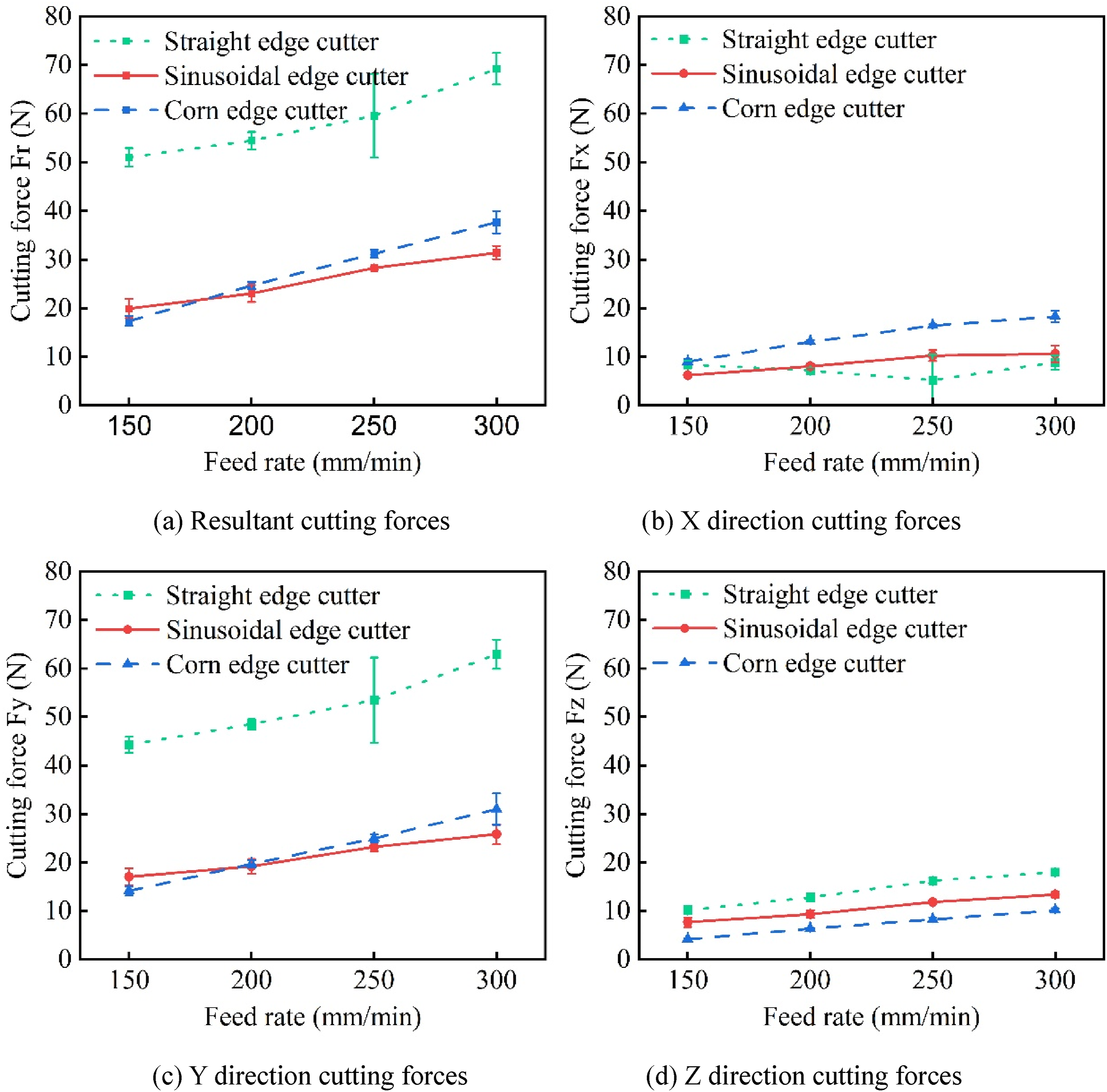
Surface morphologies
The sidewall surface morphologies of bone milling under different type cutters are presented in Figure 5. The maximum sizes of burrs for straight, sinusoidal, and corn edge cutters are 220, 115, and 35 μm at a feed rate of 150 mm/min, respectively. For the straight edge milling cutters, the surface presents large high burrs and delamination damages, and the bone edge region appears tearing damages and microcracks. However, sinusoidal edge milling cutters generated fewer burrs (Figure 5(b)), and the corn edge milling cutters generated almost no burrs and delamination damages, and the contour between the side wall and upper surface was clear (Figure 5(c)). This was related to the helix direction of the cutter. The cutting edge of corn milling cutter consisted of a right helix main cutting edge and a left helix secondary cutting edge. The secondary cutting edge of left helix generated a downward cutting motion along the sidewall, effectively removing burrs generated by the main cutting edge and suppressing the formation of cutting burrs. The straight edge and sinusoidal edge milling cutters have a right helix structure, and the chips gradually move from the lower part of the sidewall to the upper part, which causes tool compression and edge tearing. This will lead to cracks and fractures at the edges. When the material flows to the top of the sidewall, due to the elastic deformation of the bone caused by tool compression, the tool cannot remove the materials, resulting in the formation of chip burrs at the top of the sidewall. Furthermore, for straight edge cutter, the continuous cutting edge caused the impact on bone resulting in delamination damage. Surface morphology of bone tissue sidewall (Spindle speed: 2500 r/min, feed rate: 150 mm/min). (a) Straight edge cutter, (b) Sinusoidal edge cutter, (c) Corn edge cutter.
The side wall cracks in bone tissue samples after side milling are shown in Figure 6. The propagation direction of bone cracks during milling with sinusoidal edge milling cutters and corn edge milling cutters is mainly transverse. The side wall surface milled by a straight edge milling cutter is smooth, and the crack propagation is mainly longitudinal direction. Cement line is the interface between bone and interstitial matrix, with low toughness and weak boundary effect, which is prone to crack initiation and propagation.
54
When subjected to significant impact or milling force during milling, it can cause bone fractures and extend along the cement line into the interior of the bone,
21
resulting in damage to surrounding tissues. Side wall cracks in bone tissue samples after side milling (spindle speed: 2500 r/min, Feed rate: 150 mm/min). (a) Straight edge cutter, (b) Sinusoidal edge cutter, (c) Corn edge cutter.
The surface three-dimensional morphologies of varied milling cutters are exhibited in Figure 7. The cutting surface of straight edge milling cutter is relatively flat. The cutting surface of the sinusoidal edge cutter is wavy with a significant height difference. The cutting surface of the corn edge cutter has smaller fluctuations, but the cutting plane is smoother compared to the sinusoidal edge cutter. Surface three-dimensional morphologies of different milling cutters (Spindle speed: 2500 r/min, Feed rate: 150 mm/min).
The surface roughness Ra of the bone straight, sinusoidal, and corn edge cutters side milling are 0.477, 1.188, and 1.316, respectively. The surface roughness of multi-tooth milling cutter milling is higher. This because the multi-tooth cutting tools have missed cutting situations, resulting in uneven cutting surfaces. The three-dimensional morphology of cutting surface is related to the micro tooth shape, phase difference of micro teeth, and feed. By designing complementary cutting spaces between adjacent teeth, the effective cutting area of micro teeth between adjacent edges can complement each other in cutting. The multi-edge cutter complementary cutting reduces the continuous missed cutting area, thereby improving the flatness of the cutting surface, similar to the surface morphology of straight edge cutting. Sugits et al. 55 designed a micro tooth structure with straight staggered teeth, resulting in a flat cutting surface with minimal cutting force.
Chip morphology
The chip morphology of straight edge milling cutter under different feed rates is exhibited in Figure 8. The chips present a continuous curled shape. As the feed rate increases, the cracks on the back of the chips become clear. This is because as the feed rate increases, the cutting thickness per tooth increases. When the bone cutting energy release rate reaches its critical value, unstable brittle fracture occurs, resulting in the formation of larger cracks.
21
Regular wrinkles were observed from the front of the chips (Figure 8(a)). Additionally, the ultrasonic vibration further promotes the appearance of chips. During the formation process of the chip, the bone fracture of the chips propagated along the shear plane.
16
Chip morphology of straight edge milling cutter (Spindle speed: 2500 r/min).
The chip morphology of sinusoidal cutter under different feed rates is shown in Figure 9. The chips are small-sized fragmented shape extruded chip. The chips’ front surface presents a sinusoidal shape, and cracks appeared on the back surface. With the increasing of feed rates, the surface of the chips experiences more severe extruding and tearing. At a feed rate of 150 mm/min, some chips appear slightly curled. Microcracks have appeared on both sides of the chip, and the cracks tend to converge towards the middle. At high feed rates, the chip is squeezing chips. As the feed rate increases, the chip length is relatively short, and cracks tend to converge towards the middle, and even penetrates the entire chip. Due to the larger radius of the micro tooth tip, the chips present thick at the middle and thin at both sides. While the edge radius on both sides of the tooth tip gradually decreases, and the cutting thickness also decreases accordingly. At lower feed rates, larger cracks appear on the back of the chips, weakening the continuity of the chips. Chip morphology of sinusoidal edge milling cutter (Spindle speed: 2500 r/min).
The chip morphology of corn edge cutter under different feed rates are exhibited in Figure 10. The chips present large curled shapes and small broken strips two types. As the feed rate increases, the small strip-shaped chips gradually decrease. Corn edge milling cutters have multiple cutting edges, resulting in a smaller cutting thickness per tooth, which is beneficial for chip broken. When the cutting thickness is low, the form of chip debris is generated. When the cutting thickness is increased, the chips appear curled. Therefore, large curled chips are generated by the main cutting edge. Under the action of the axial amplitude of cutting tool, the secondary cutting edge will also cut the bone surface and produce debris. Different chip morphology characteristics generated by different milling cutters (Figures 8–10). The chip size generated by straight edge cutting is significantly larger than that of sinusoidal and corn edges. This because a long distance of continuous contact between the cutting edge and the bone, which also contributed to its high cutting forces. Chip morphology of corn edge cutter (Spindle speed: 2500 r/min).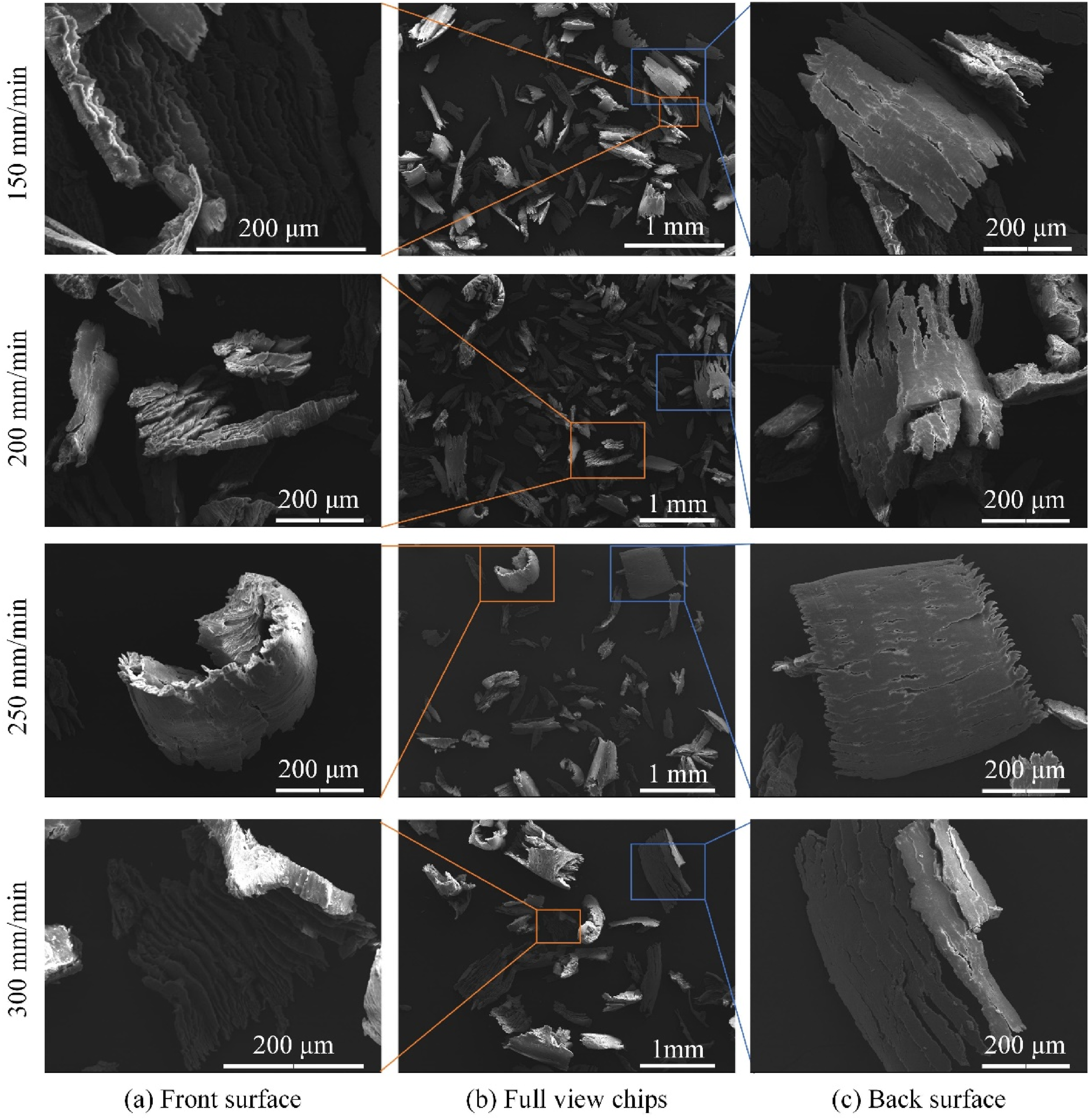
Cutting mechanism of bone multi-tooth milling cutter ultrasonic vibration milling
The tool cutting edge trajectory is unfolded along the Y0-axis direction to the Y0-Z0 plane to investigate the squeezing interference of multi-tooth flank surface. The influence of feed rate is ignored due to its lower value. Therefore, the trajectory equation is in the Y0-Z0 plane as follows:
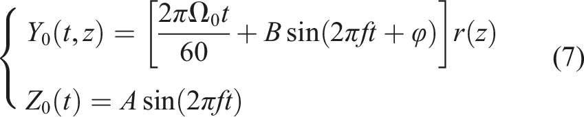
The slope of the tool trajectory changes with time t as follows:

The tool path is influenced by the spindle speed, ultrasonic frequency, and longitudinal and torsional amplitude. The interference conditions of multi-tooth flank surface in ultrasonic vibration cutting are shown in the Y0-Z0 plane (Figure 11). The squeezed interference conditions between multi-tooth flank surfaces and workpiece can be determined by the slope of cutting edge. The slopes of the upper and down cutting edge of micro tooth are defined as Interference conditions of multi-tooth flank surface in ultrasonic vibration cutting.
The inclination angles of down and upper cutting edges of sinusoidal and corn edge cutter are 70° and 250°, and 0° and 180°, respectively. The interference conditions of the multi-tooth cutting surfaces of the two cutters are exhibited in Figure 12. The unfolding trajectory of Y0-Z0 plane under experimental parameters is shown by the dashed line. The minimum slope during the descent stage of tool path is Multi-tooth interference conditions of sinusoidal and corn edge milling cutters in ultrasonic vibration cutting.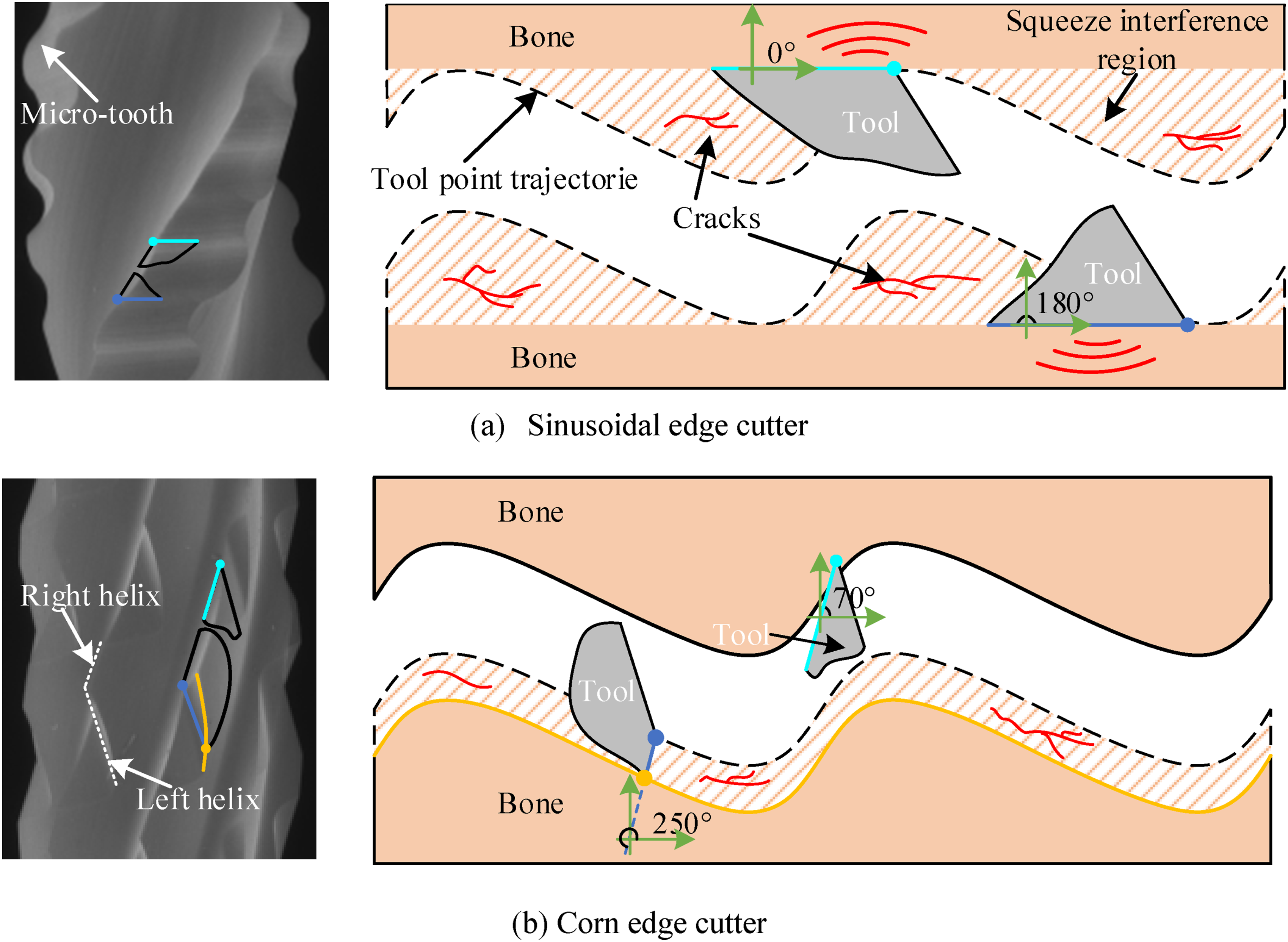
Conclusions
This paper proposes a novel multi-tooth milling cutter longitudinal torsional ultrasonic vibration assisted milling (LTVUM) method for cortical bone cutting, aiming at reducing cutting force and inhibiting cutting damages. The cutting force, surface morphology, and chip morphology of bone milling with straight edge, sinusoidal edge, and corn edge cutters under LTVUM were first studied. The effect of multi-tooth milling cutters on milling system results under LTVUM was studied. The cutting mechanisms of low damage for multi-tooth milling were revealed. The key conclusions are as follows: (1) The resultant cutting forces of sinusoidal and corn edge cutters are significantly lower than that of straight edge. The resultant cutting forces of sinusoidal and corn edge cutters are decreased by 52.58%–61.01% and 45.60%−65.96%, respectively. (2) The multi-tooth milling cutter effectively suppresses the generation of chip burrs and tearing damages on the side wall. The straight edge milling cutters generated large burrs and tearing damages, and tearing damage and micro cracks occurred at bone edge. However, sinusoidal edge milling cutters generated fewer burrs, and the corn edge milling cutters generated almost no burrs and tearing damages. (3) The chip size generated by straight edge cutting is significantly larger than that of sinusoidal and corn edges. The chips of straight edge cutter present a continuous curled shape, whereas the corn milling cutter is large curled shapes and small broken strips. (4) For straight edge cutters, the flank face interferes with bone material in LTVUM. For sinusoidal edge cutter, the upper and down flank surfaces of secondary cutting edge also impact bone material. However, the secondary cutting edge of corn edge cutter can participate in cutting and reduce the tool squeeze interference, resulting in a low tearing damage.
Footnotes
Declaration of conflicting interest
The author(s) declared no potential conflicts of interest with respect to the research, authorship, and/or publication of this article
Funding
The author(s) disclosed receipt of the following financial support for the research, authorship, and/or publication of this article: R&D Program of Beijing Municipal Education Commission (KM202210005033), National Natural Science Foundation of China (52105424) and Beijing Natural Science Foundation (7232331, L242111).