
Abstract
This study analyzes the low-velocity impact response of cantilever sandwich beams with foam cores and carbon nanotube (CNT) reinforced facesheets. Using the fifth-order shear and normal deformation theory, we explore three CNT distribution types through the thickness of the facesheets: uniformly distributed UD, functionally graded-V FG-V, and functionally graded-Λ FG-Λ. The contact force during impact is calculated according to Hertz contact law. Our findings indicate that the FG-V distribution offers the highest contact stiffness, resulting in reduced deflection compared to UD and FG-Λ distributions. Additionally, an increase in the core-to-face thickness ratio leads to decreased deflection and increased contact force, attributed to enhanced beam stiffness. The volumetric fraction of CNTs also plays a critical role, increased CNT content raises beam stiffness, decreasing deflection and enhancing contact force. Furthermore, the impactor’s initial velocity directly influences the deflection and contact force, with higher velocities leading to greater deflections due to increased kinetic energy. This comprehensive analysis underscores the significant effects of CNT distribution, volumetric fraction, and geometrical parameters on the dynamic response of sandwich beams under impact conditions.
Keywords
Introduction
In recent years, Carbon Nano Tubes (CNTs) have acquired significant interest as a unique type of material. CNTs demonstrate exceptional physical and chemical characteristics, including high stiffness, high strength, very low density, and high aspect ratio. These features qualify them excellent as candidates for strengthening composites. As a result, CNTs are a promising material for various industries, including aerospace, automotive, and electronics, for their potential to enhance the properties of materials and improve their overall performance. The single-walled carbon nanotube (SWCNT), as described in Iijima and Ichihashi (1993) 1 and Bethune and Kiang (1993), 2 is a cylindrical structure with a diameter of approximately 1 nm and a length on the order of centimeters. This is achieved by seamlessly rolling a single graphene sheet. The multi-walled carbon nanotube (MWCNT), on the other hand, is composed of an array of these cylinders arranged concentrically with a separation distance of 0.35 nm. The diameter of MWCNTs varies from 2 to 100 nm and they can attain lengths in the tens of microns [Iijima (1991) 3 ]. CNTs have a small percentage of weight (approximately 25) and this feature can raise the strength and stiffness of the composites remarkably [Hieu and Van Tung (2019), 4 Long and Van Tung (2020), 5 Van Tung and Trang (2020), 6 and Trang and Van Tung (2023) 7 ]. In the Ma and Haque (2012) 8 study, the mechanical properties analysis revealed that single-walled carbon nanotubes had a positive impact on the tensile properties, particularly when the dispersion of the nanotubes within the matrix was optimal. Yazdi (2017) 9 studied on geometrical nonlinear flutter of single-walled functionally graded carbon nanotube reinforced composite plates integrated with piezoelectric layers subjected to supersonic flow on nonlinear elastic foundation and investigated the effects of volume fraction of carbon nanotubes, large amplitude, different distribution types, piezoelectric layers, and applied voltage on flutter pressure. The impact of non-functionalized MWCNTs on the vibration damping characteristics of neat epoxy resin examined by Avil and Kadioglu (2018). 10 The findings revealed that even with a mere 0.1 wt incorporation of carbon nanotubes into the neat epoxy resin, they not only enhanced the mechanical properties (flexural strength and modulus) but also influenced the vibration behavior (damping ratio) of the epoxy. Yuan and Allegri (2012) 11 compared the damping characteristics of the baseline rudder configuration with constrained layer Al/3M467 skin patches and multi-walled carbon nanotube dispersion in the carbon/epoxy material, providing insights for improved structural damping in aerospace applications. They demonstrated that the inclusion of multi-walled carbon nanotubes for passive damping in the rudder design significantly increases dynamic stiffness while imposing minimal weight penalty. The results in Tanjheel and Md Ekramul (2017) 12 investigation on the individual effects of nanoclay and MWCNTs and also a hybrid combination of both on the enhancement of impact performance in CFRP composites indicated that the inclusion of MWCNTs and nanoclay led to slight improvements in the impact properties and a reduction in the damaged area of the composite samples. On the other hand, an experimental study done by Meguid and Sun (2004) 13 indicated that there is a limit to the amount of CNTs, and rising the amount of CNTs causes of decreasing tensile and shear properties of composite reinforced with CNTs.
Functionally graded materials (FGMs) these days fascinated high notice as a new class of material. Liew and Zhao (2011) 14 have done a review study on FGMs materials and their advancements and applications. In their study, various analysis of composite structures, such as static and dynamic analysis, free vibration, buckling, and non-linear analysis, are discussed. Remarkable properties of CNTs and FGMs can get together in the case of FG distribution of CNTs as reinforcement. The results of Shen (2009) 15 investigation on the nonlinear bending behavior of FG nanocomposite plates reinforced with SWCNTs demonstrated that FG reinforcement significantly enhances the load-bending moment curves of the plates. Ghorbanpour Arani and Mosayyebi (2016) 16 focused on the damped free vibration of a microplate composed of carbon nanotube reinforced composite material. Specifically, four types of single-walled functionally graded distribution patterns along the thickness direction of the microplate investigated. The influence of volume fraction and distribution type of carbon nanotubes resulted in a notable effect on the vibration of sandwich plate. The results of Wang and Shen (2012) 17 study on the nonlinear bending analysis and nonlinear vibration of a sandwich panel with uniform and FG distributions of CNT reinforced facesheets supported on an elastic foundation indicated that the linear distribution of CNTs affects the nonlinear bending behavior and nonlinear vibration characteristics of the sandwich panel. Kamarian and Shakeri (2015) 18 investigated the free vibration of a sandwich beam incorporating FG-CNTs in nanocomposites and supported on a Pasternak foundation. The results demonstrated that the agglomeration of carbon nanotubes affects the natural frequencies of the structure. Wang and Xu (2014) 19 presented a theoretical analysis of the low-velocity impact response of a sandwich panel that incorporates FG-CNTRC facesheets. The numerical results of Jedari Salami (2017) 20 study on the response of a sandwich beam with CNTRC facesheets and a soft core subjected to the impacting mass based on the Extended High Order Sandwich Panel Theory indicated that the use of FG-CNTs in the facesheets has a significant impact on the impact response of the sandwich panel. Mohammadimehr and Mostafavifar (2016) 21 studied the free vibration analysis of a sandwich plate that was reinforced with FG-CNTs and had a transversely flexible core. The outcomes of the research demonstrated that the sandwich plate that incorporated a distribution of carbon nanotubes in the facesheets known as X, exhibited a higher frequency in comparison to the other types. Raissi (2020) 22 presented a novel approach leveraging Layerwise Theory (LT) and Higher-Order Shear Deformation Theory (HSDT) to analyze the stress distribution within a three-layer spherical sandwich shell subjected to internal blast pressures generated by a controlled TNT detonation. The complex dynamic response of the structure to both positive and negative phases of blast pressure is explored in detail, providing a comprehensive understanding of the mechanical behavior of such advanced composite structures in extreme conditions. Raissi (2021) 23 focused on the time-dependent analysis of a simply supported sector of a spherical sandwich shell, featuring piezoelectric face sheets and a functionally graded carbon nanotube (FG-CNT) core, subjected to low-velocity impacts. The numerical solutions obtained through the finite difference method reveal the pronounced influence of FG-CNT mechanical properties on stress distribution and highlight the dynamic voltage variations induced by the impact, offering valuable insights for the design and analysis of advanced composite structures. Raissi (2020) 24 presented a novel layerwise theory combined with higher order shear deformation theory to analyze the stress distribution in a three-layer, simply supported sector of cylindrical sandwich shells featuring piezoelectric face sheets and functionally graded carbon nanotube (FG-CNT) cores. The choice of FG-CNT core has a notable effect on the stress components over time, underscoring the importance of material composition in the design of such structures.
The fifth-order shear and normal deformation theory (FOSNDT) is an extension of the classical plate theory and takes into account the effects of transverse shear deformation and normal deformation. This theory is based on the concept of displacement fields that include higher order terms for shear and normal deformations. FOSNDT is capable of accurately predicting the mechanical response of laminated composite plates subjected to various loading conditions, including bending, buckling, impact, and vibration. Bharti and Sayyad (2020) 25 utilized fifth-order shear and normal deformation theory for the static analysis of laminated composite and sandwich simply supported spherical shells subjected to a sinusoidal load. The conclusions indicated the developed fifth-order theory exhibits close agreement with the exact elasticity solution provided by Pagano (1970). 26 Comparative analysis with existing results of Sayyad and Ghumare (2019) 27 study on the static behavior of FG plates under mechanical loads by FOSNDT showed that the FOSNDT provides accurate predictions for the structural analysis of isotropic and FG plates. Ghumare and Sayyad (2017) 28 presented FOSNDT for the static bending and elastic buckling analysis of FG beams with power-law distribution (P-FGM) of material properties along the thickness direction. The results demonstrated that the FOSNDT theory is highly accurate and efficient in predicting the bending and buckling responses of FG beams. Naik and Sayyad (2020) 29 utilized FOSNDT for bending analysis of laminated composite plates under mechanical and hygrothermal environmental loading. The study provided valuable insights into the behavior of laminated composite plates under combined hygrothermomechanical loading. The Ghumarea and Sayyad (2020) 30 analytical solution based on the FOSNDT for the bending behavior of FG beams under hygro-thermomechanical loading indicated that the FOSNDT solution is simple and highly accurate in predicting the bending behavior of FG beams under both linear and non-linear hygro-thermo-mechanical loadings.
As the above literature survey accepts, and to the best of the author’s knowledge, there is no work on the low-velocity impact response of a cantilever sandwich beam with FG-CNTRC facesheets and soft core based on fifth-order shear and normal deformation theory and parametric study for investigating the influence of some important parameters. The current study compares several FG-CNTRC contributions by leveraging the advanced capabilities of Fifth-Order Shear Deformation Theory (FOSNDT). First and foremost, FOSNDT enhances the accuracy of displacement predictions by capturing shear and normal deformations that are often overlooked by lower order theories, thus providing a more realistic assessment of structural behavior, especially in thick structures. Furthermore, this theory alleviates the issue of shear locking commonly encountered in thin-walled structures, resulting in improved numerical performance and convergence during simulations. Additionally, FOSNDT offers a superior representation of stress distribution across the thickness of composite laminates, which is crucial for analyzing potential failure mechanisms in these materials. The theory also facilitates a nuanced understanding of layered composites, allowing for a detailed analysis of the individual contributions of each layer to the overall structural response, a key consideration in fields such as aerospace and civil engineering where material anisotropy plays a significant role. Lastly, FOSNDT is compatible with nonlinear analysis, enabling accurate predictions of material behavior under extreme loading conditions, thus broadening its applicative potential. These novelties position FOSNDT as a pivotal approach for improving the analysis and design of composite materials, reinforcing its relevance in contemporary research and practical applications.
Basic formulation
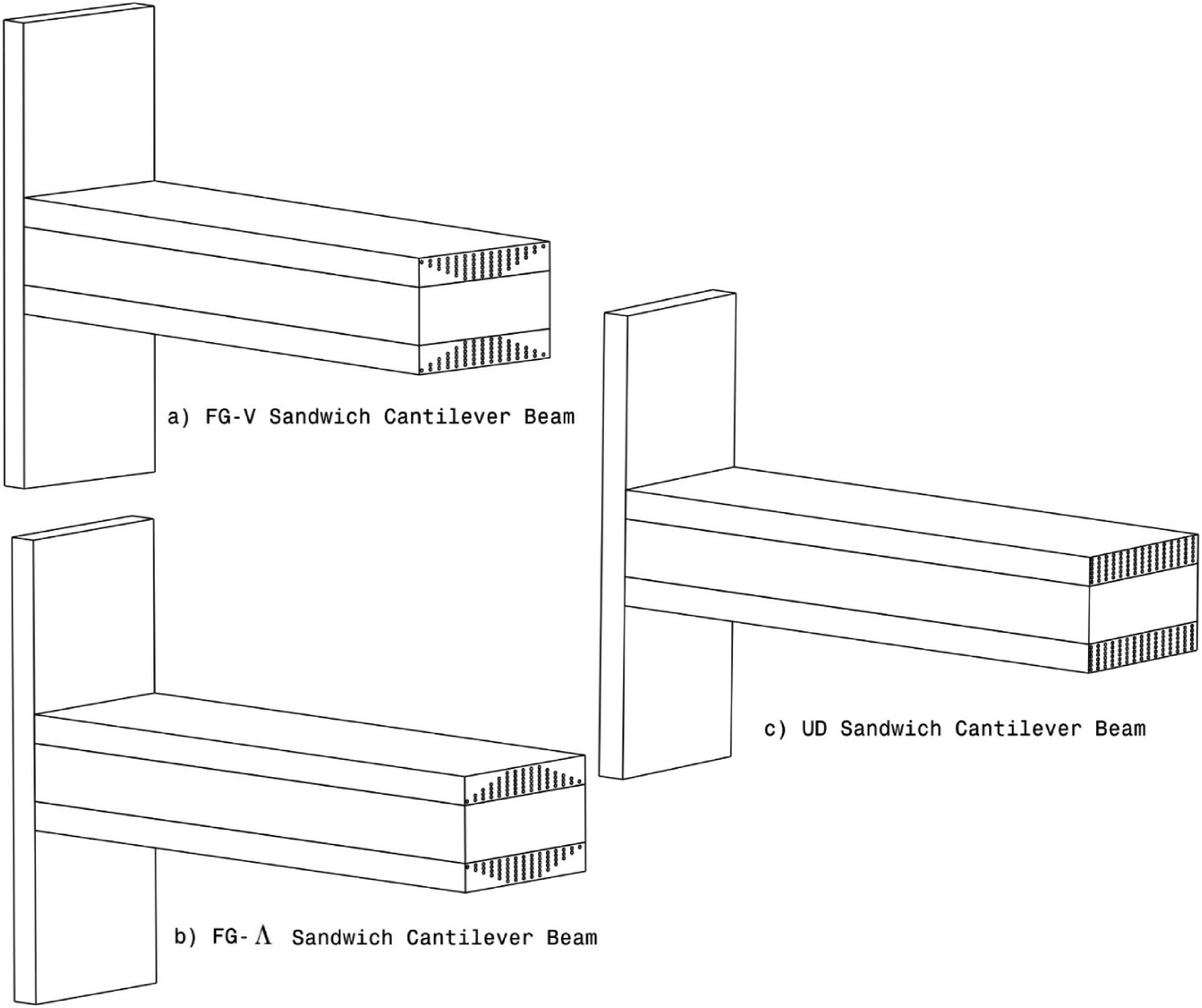
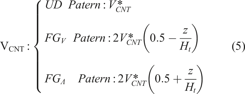
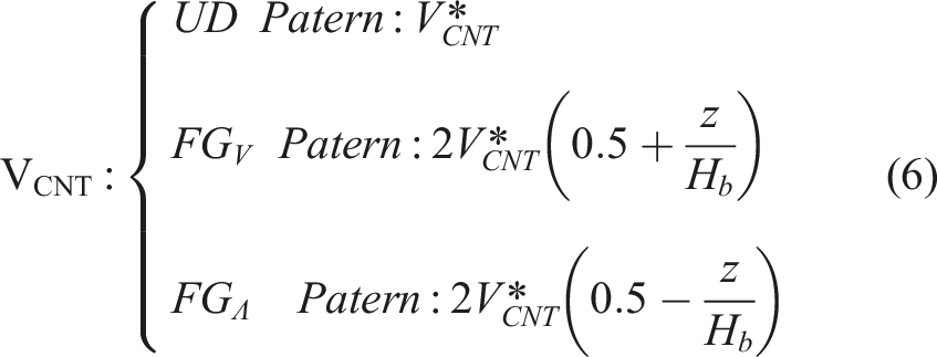
A cantilever sandwich beam consists of two stiff and thin facesheets that are separated by a thick, soft core. In this investigation, the facesheets are fabricated of Carbon Nanotube Reinforced Composites (CNTRCs), Single-Walled Carbon Nanotubes as reinforcement distributed in either uniform distributed or functionally graded along the thickness direction. The sandwich beam’s dimensions include length (L) and width (b), while the top and bottom CNTRC facesheets possess respective thicknesses of Ht and Hb. Additionally, a homogeneous soft core layer, with a thickness denoted as C, is present within the beam’s configuration, as illustrated in Figure 1. For this study, three distinct types of carbon nanotube reinforced cantilever beams have been considered, including a uniformly distributed (UD) case and two different functionally graded (FG) cases known as FG-V and FG-Λ. In line with convention, a FG-V sandwich cantilever beam is referred to as a beam where the top face sheet is FG-V type, while the bottom one is FG-Λ type. Conversely, in a FG-Λ sandwich cantilever beam, the distribution pattern of the facesheets is vice versa. Patterns of distribution of the UD and FG-CNTRC cantilever beams are illustrated in Figure 2. The CNTRC facesheets are assumed to be comprised of a composite mixture involving10,10 armchair SWCNTs as the reinforcing agent. This mixture exhibits a graded distribution along the thickness direction, and the matrix material is assumed to possess isotropic and homogeneous characteristics. The effective material properties of the twophase composites, comprising the CNTs and the isotropic polymer matrix, can be estimated using the modified rule of mixtures, as previously elucidated by Shen (2011).
31
For this, the conventional mixture rule approach is enhanced through the introduction of efficiency parameters. These parameters are utilized to harmonize the data obtained through molecular dynamics simulations and the mixture rule. Consequently, the axial and shear modulus can be expressed as functions, as outlined in Shen’s (2011)
31
work. Geometrical structure of the cantilever sandwich beam. Various distribution of carbon nanotube reinforced composite.(a) FG-V sandwich cantilever beam (b) FG-Λ sandwich cantilever beam (c) UD sandwich cantilever beam.


Top – facesheet
Bottom – facesheet
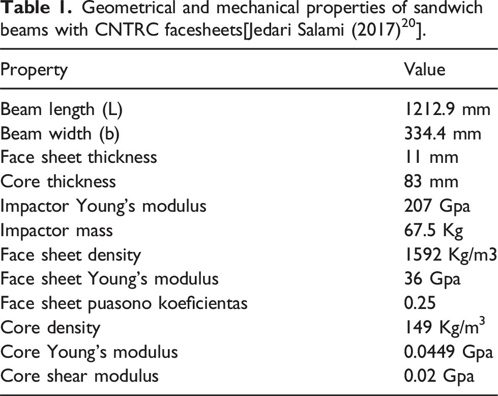
Geometrical and mechanical properties of sandwich beams with CNTRC facesheets[Jedari Salami (2017) 20 ].
Density of nanotube reinforced composite is obtained by equation (7) [Wang and Xu (2014)
19
].
The effective Poisson ratio depends weakly on position [Shen (2011)
31
] and is described by equation (8):
Fifth-order shear and normal deformation theory (FOSNDT) for facesheets and core
Axial and transverse displacement components of the top and bottom facesheets and soft core are determined based on fifth-order shear and normal deformation theory (FOSNDT) as follows [Ghumare and Sayyad (2017)
28
]:
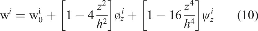
The index (i = t or (b) refers to the top and bottom facesheets, and the index (i = (c) points to the core.
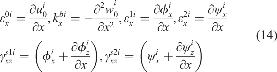
Based on the displacement fields, normal and shear strain components of facesheets and core as follows [Ghumarea and Sayyad (2017)
28
]:


The stress strain relations for the top and bottom facesheets and core are obtained using the linear constitutive relations indicated in equation (15) [Ghumarea and Sayyad (2017)
28
].
Governing equations
In the analysis of sandwich beams, the derivation of accurate and efficient governing equations of equilibrium is crucial for predicting their structural behavior. The Ritz method, based on the principles of variational calculus, allows for the approximation of the beam’s total potential energy function through a suitable trial function.
The total potential energy of a sandwich beam 
The strain energy of the facesheets and core is derived from the integral of the product of stress and strain over the entire beam volume. This integral represents the work done by the internal forces as the beam undergoes deformation. The strain energy of the top and bottom facesheets, and core acquired by equation (15):
The kinetic energy of the facesheets and core is derived from the integrating product of facesheets and core density and square of displacement over the entire beam volume. Equations (18) and (19) are the kinetic energy of the sandwich beam (which includes the kinetic energy of the facesheets and core) and kinetic energy of the impactor (

The relation between contact force and indentation of the top face sheet derived by Hertz contact law. So, the potential energy of the contact force is equal to [Wang and Xu (2014)
19
]:
In the equation of 
The strain energy of the top and bottom facesheets and core in terms of the displacement components are obtained By substituting stress–strain relationships (equations (15) into Equation (17)), and integrating over the strain terms and substituting the strain-displacement relations (equations (11)–(13)) as follows: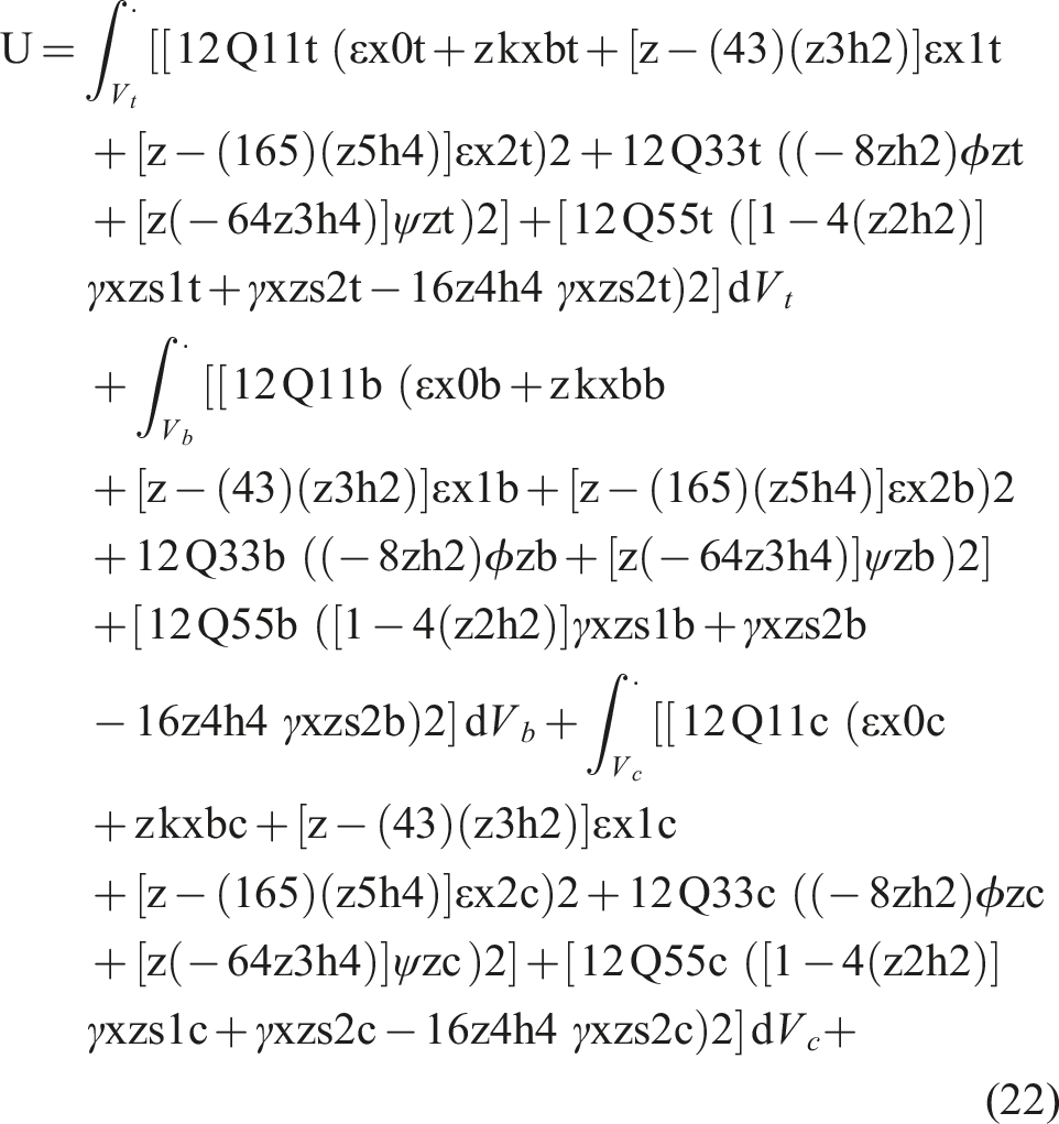
The kinetic energies of the facesheets and the core in terms of displacement component are extracted by substituting the displacement components of the facesheets and core (equations (9) and (10) into equation (18) as follows: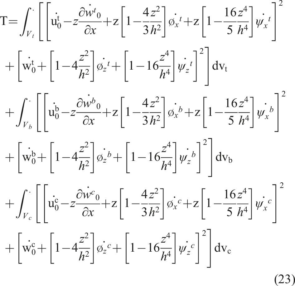
By the Ritz method, the assumed displacement functions are determined by ensuring the fulfillment of the essential boundary conditions. Furthermore, if a harmonic variation of displacements is postulated, the displacement fields can be expressed as follows: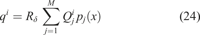

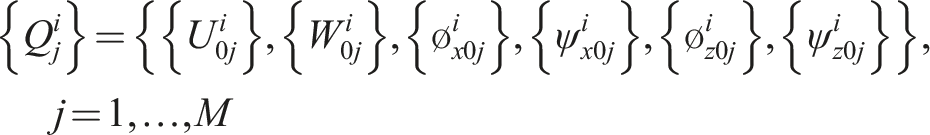

By considering equation (25), equation (24) is substituted in to equations (20), (22) and (23). So, the total strain and kinetic energies and potential of external works can be obtained as functions of unknown displacement coefficients of the facesheets and the core. Moreover, the equations obtained eliminate the dependence of the unknown variables on the spatial coordinates. Finally, by inserting equations (20), (22) and (23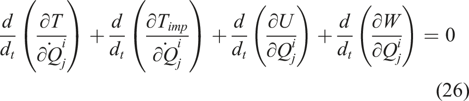
The resulted equations from equation (26) are a system of 18M second-order differential equations in the time domain and can be formulated in the compact matrix form as follows: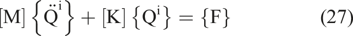

The comprehensive definitions of
Additionally, Fimp can be expressed in relation to the newly defined shape functions as follows: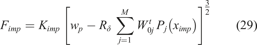
Multiple numerical integration methods exist for the integration of second-order equations in the time domain. In this research, the obtained time-dependent equations are subsequently solved using the fourth-order Runge-Kutta method implemented in MATLAB software. The initial values for displacement and velocity are initialized to zero, as the motion of the panel starts from a state of rest. Therefore, the initial conditions can be defined as follows:
Validation
In order to validate the analysis of low-velocity impact on a cantilever sandwich beam with a foam core and carbon nanotube reinforced facesheets using the fifth-order shear and normal deformation theory (FOSNDT), this analytical model is executed for the analyzed sandwich beams in reputable articles, and the results are compared. In the initial investigation, the analytical results presented by Jedari Salami (2017) 20 for low-velocity impact analysis on a sandwich beam are considered. In this analysis, the sandwich beam is supported on a simple support, and the Extended high-order sandwich panel theory is utilized for the analytical model. To validate the analytical model, the same analysis is performed using the fifth-order shear and normal deformation theory (FOSNDT).
As shown in Figure 3 the sandwich beam is placed on a simple support. The boundary conditions for the simple support are defined as follows: Sandwich beam with a foam core and carbon nanotube reinforced facesheets on a simple support.

The sandwich beam consists of two composite facesheets and a foam core, with the composite facesheets reinforced by functionally graded carbon nanotubes. After modifying the boundary conditions, the deflection plot over time is generated by entering the mechanical and geometrical properties of the analyzed beam from the Jedari Salami (2017)
20
analysis, as listed in Table 1, and the result is compared. The comparison of the result is shown in Figure 4. Comparison displacement of the sandwich beam based on Jedari Salami (2017)
20
solution with present solution.
In Figure 4 the deflection of the sandwich beam calculated from the analytical model is compared with the results obtained by Jedari Salami (2017). 20 The maximum deflection of the beam was 9.4 mm in the Jedari Salami (2017) 20 analysis and 9.1 mm in the presented analytical model. The percentage difference between the obtained values for the maximum deflection of the sandwich beam is 3.15. This difference could be attributed to the disparity between the fifth-order shear and normal deformation theory (FOSNDT) and the Extended high-order sandwich panel theory.
Geometrical and mechanical properties of sandwich beams with CNTRC facesheets[Ranjbar and Feli (2018)]. 35

The low-velocity impact is applied at the center of the beam. The configuration of the cantilever beam is depicted in Figure 5. After inputting the geometric and mechanical properties of the cantilever beam, the contact force-time graph is plotted in Figure 6. According to the analytical model presented in this study, it is compared with the results obtained from the Ranjbar and Feli (2018).
35
As shown in Figure 6, the maximum contact force according to the Ranjbar and Feli (2018)
35
is 730 N. This value for the presented analytical model is 710 N, resulting in only a 2.73 difference. This small difference confirms the validity of the analytical model proposed in this study. Cantilever sandwich beam used in Ranjbar and Feli (2018).
35
Comparison the contact force of the cantilever sandwich beam based on Ranjbar and Feli (2018)
35
solution with present solution.

Parametric study
Geometrical and mechanical properties of sandwich beams with CNTRC facesheets.

Influence of initial velocity of the impactor
The results of the analytical model are extracted for three initial impact velocities: 2, 5, and 8 (m/s), and the effect of changing this parameter on the deflection of the cantilever sandwich beam and the impact force is examined.
The initial kinetic energy of the impact is dependent on the mass and initial velocity of the impactor. To investigate the effect of the initial velocity, a constant mass of the impactor is considered. The contact force graph for different initial impact velocities is shown in Figure 7. The results indicate an increase in the contact force with an increase in the initial impact velocity. For an initial impact velocity of 2 m/s, the maximum contact force is 445 N. With an increase in the initial velocity to 5 m/s, the maximum contact force reaches 975 N. At an initial velocity of 8 m/s, the maximum contact force is 1410 N. The values of the contact force for different initial velocities are presented in Table 4. Contact force of the cantilever sandwich beam for the different initial velocity of the impactor. Values of the contact force for different initial velocities.

Therefore, it can be concluded that the contact force of the cantilever sandwich beam is directly proportional to the initial impact velocity. The reason for the increase in contact force with increasing initial impact velocity is the increase in the kinetic energy of the impactor.
Figure 8 depicts the deflection of the cantilever sandwich beam for the initial velocities of 2, 5, and 8 (m/s). The results indicate that for an initial impact velocity of 2 (m/s), the maximum deflection of the sandwich beam is 1 mm. This maximum value increases to 1.9 mm for an initial velocity of 5 (m/s). For an initial velocity of 8 (m/s), the maximum deflection of the sandwich beam is 2.9 mm. The values of the sandwich beam deflection for different initial velocities are presented in Table 5. Deflection of the cantilever sandwich beam for the different initial velocity of the impactor. Values of the sandwich beam deflection for different initial velocities.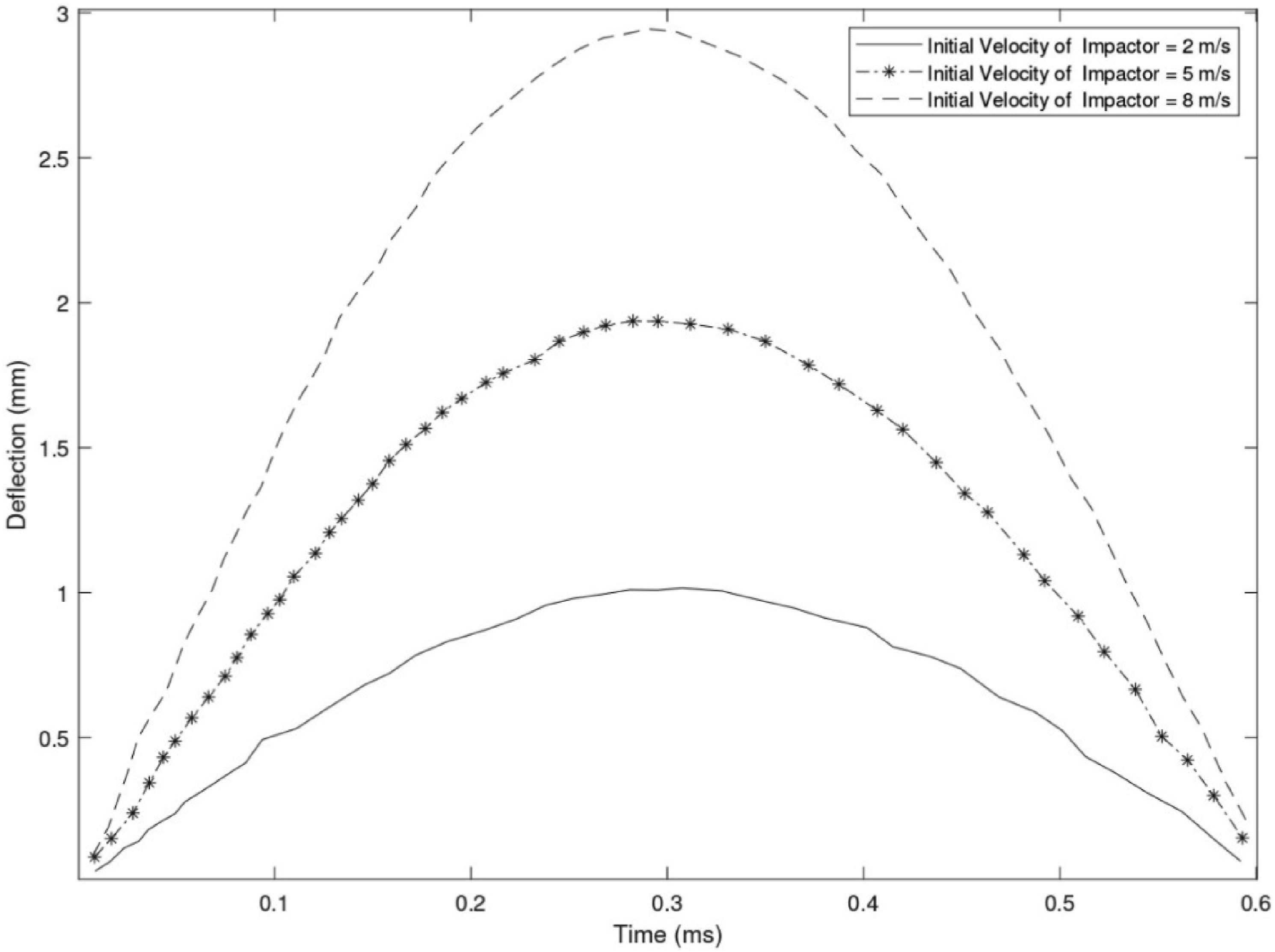

Therefore, the deflection of the cantilever sandwich beam is directly proportional to the initial impact velocity. The most important reason for the increase in the deflection of the sandwich beam with increasing initial impact velocity is the increase in the kinetic energy of the impactor, which is caused by the increase in the initial velocity of the impactor.
Influence of volume fraction of carbon nanotubes
In the presented analytical model, the density, Young’s modulus, shear modulus, and Poisson’s ratio of the bottom and top facesheets depend on the volume fraction of carbon nanotubes. The influence of the volume fraction of carbon nanotubes on the contact force and deflection of the cantilever sandwich beam is examined.
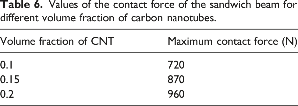
Figure 9 illustrates the impact of the volume fraction of carbon nanotubes on the contact force resulting from a low-velocity impact. According to Figure 9, when the volume fraction of carbon nanotubes is 0.1, the maximum contact force is 720 N. By increasing the volume fraction to 0.15, the maximum contact force reaches 870 N. The maximum contact force is 960 N when the volume fraction of carbon nanotubes is 0.2. The maximum contact forces for the three volume fractions of carbon nanotubes are presented in Table 6. Contact force of the cantilever sandwich beam for the different volume fraction of carbon nanotubes. Values of the contact force of the sandwich beam for different volume fraction of carbon nanotubes.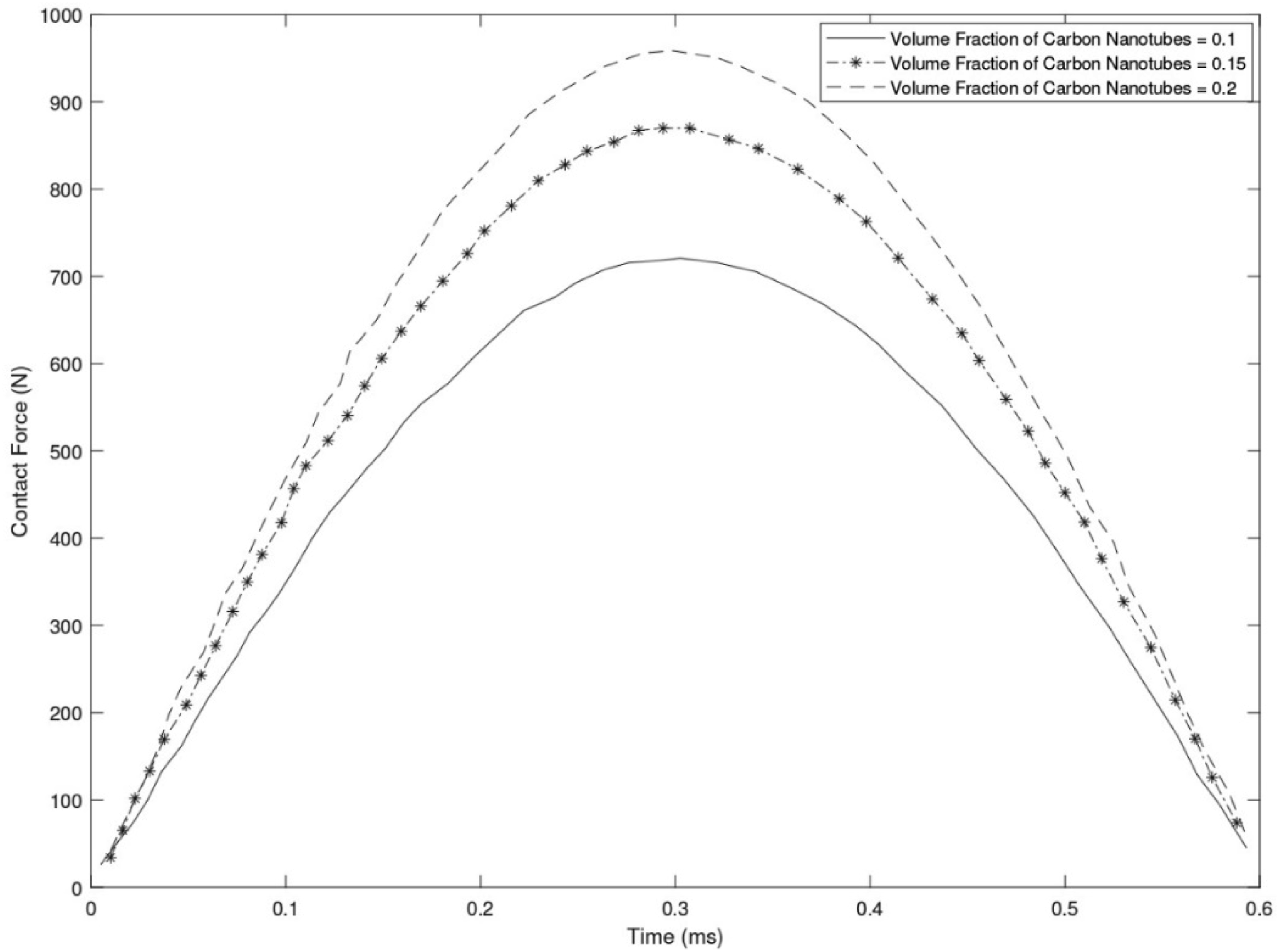
Therefore, with an increase in the volume fraction of carbon nanotubes, the contact force resulting from the impact increases. The main reason for this increase is the change in the stiffness of the beam, which is due to the difference in the volume fraction of carbon nanotubes. Considering that the sandwich beam becomes stiffer with an increase in the volume fraction of carbon nanotubes, the contact force also increases with an increase in the volume fraction of carbon nanotubes.
Figure 10 illustrates the influence of the volume fraction of carbon nanotubes on the deflection of the cantilever sandwich beam. According to Figure 10 when the volume fraction of carbon nanotubes is 0.1, the maximum deflection of the sandwich beam is 0.74 mm. By increasing the volume fraction to 0.15, the maximum deflection of the sandwich beam reduces to 0.64 mm. The deflection of the sandwich beam is 0.58 mm when the volume fraction of carbon nanotubes is 0.20. The maximum deflections of the sandwich beam for the three volume fractions of carbon nanotubes are presented in Table 7. Deflection of the cantilever sandwich beam for the different volume fraction of carbon nanotubes. Values of the sandwich beam deflection for different volume fraction of carbon nanotubes.

Based on the obtained results, the maximum deflection of the sandwich beam decreases with an increase in the volume fraction of carbon nanotubes. The main reason for this decrease is the change in the stiffness of the beam, which is caused by the difference in the volume fraction of carbon nanotubes. Considering that the sandwich beam becomes stiffer with an increase in the volume fraction of carbon nanotubes, the deflection of the sandwich beam decreases.
Influence of the core-to-face thickness ratio
The influence of the core-to-face thickness ratio on the contact force and deflection of a cantilever sandwich beam has been investigated. Figure 11 illustrates the effect of the core-to-face thickness ratio on the contact force resulting from low-velocity impact. According to Figure 11 when the core thickness is three times the face thickness, the maximum contact force is 493 N. By increasing the core thickness to five times the face thickness, the maximum contact force reaches 614 N. The maximum contact force is 735 N when the core thickness is seven times the face thickness. The maximum contact forces for the core-to-face thickness ratios of 3, 5, and 7 are provided in Table 8. Contact force of the cantilever sandwich beam for the different core-to-face thickness ratios. Values of the contact force of the sandwich beam for different core-to-face thickness ratios.

Therefore, with an increase in the core-to-face thickness ratio, the contact force resulting from impact increases. The main reason for this increase is the change in beam stiffness, which becomes higher as the core-to-face thickness ratio increases. Consequently, as the core-to-face thickness ratio increases, the sandwich beam becomes stiffer, leading to an increase in the contact force.
In Figure 12 the effect of the core-to-face thickness ratio on the deflection of the sandwich beam is illustrated. According to Figure 12 when the core thickness is three times the face thickness, the maximum deflection of the sandwich beam is 0.72 mm. With an increase in the core-to-face thickness ratio to five, the maximum deflection decreases to 0.57 mm. The maximum deflection of the sandwich beam is 0.45 mm, when the core thickness is seven times the face thickness. The maximum deflection values for the core-to-face thickness ratios of 3, 5, and 7 are provided in Table 9. Deflection of the cantilever sandwich beam for the different core-to-face thickness ratio. Values of the sandwich beam deflection for different core-to-face thickness ratios.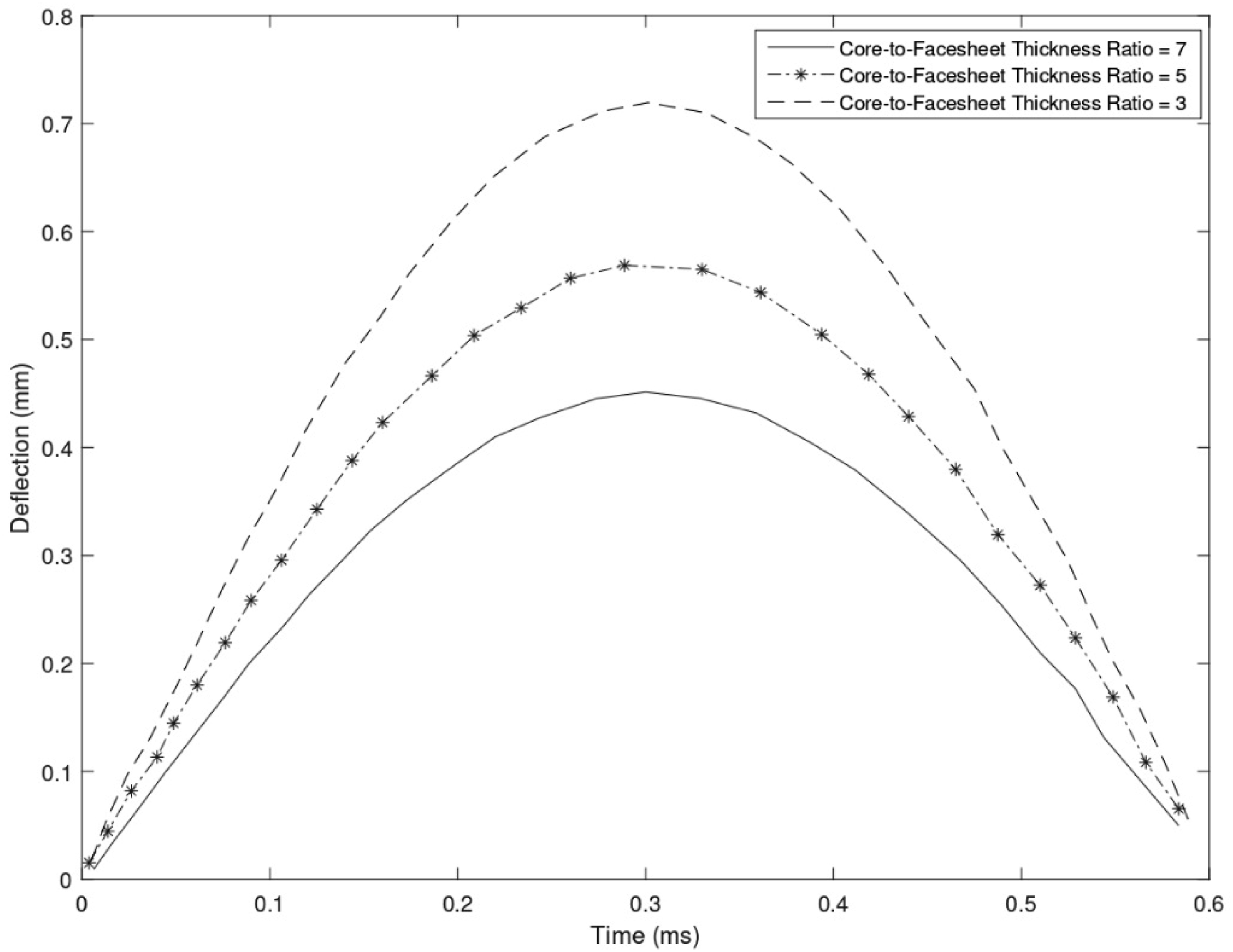

Based on the obtained results, an increase in the core-to-face thickness ratio leads to a decrease in the deflection of the sandwich beam. The reason for this decrease is the change in beam stiffness resulting from the increased core-to-face thickness ratio. As the core-to-face thickness ratio increases, the sandwich beam becomes stiffer, resulting in a reduction in deflection.
Influence of the carbon nanotube distributions
The influence of three different types of carbon nanotube distributions, namely, UD, FG-V, and FG-Λ, on the contact force and deflection of a cantilever sandwich beam has been investigated. Figure 13 illustrates the effect of carbon nanotube distribution on the contact force resulting from low-velocity impact. According to Figure 13, the FG-Λ distribution of carbon nanotubes yields a maximum contact force of 320 N. In the UD and FG-V distribution, the maximum contact force reaches to 400 and 470 N, respectively. The maximum contact forces for the three different types of carbon nanotube distributions are presented in Table 10. Contact force of the cantilever sandwich beam for the different types of carbon nanotube distributions. Values of the contact force of the sandwich beam for different types of carbon nanotube distributions.

As observed in Figure 13, among the three distributions of UD, FG-V, and FG-Λ, the FG-V distribution exhibits the highest contact stiffness, resulting in the maximum contact force among the three distributions of carbon nanotubes. On the other hand, the FG-Λ distribution, having the lowest contact stiffness, yields the lowest contact force among the three distributions. The variation in contact stiffness among these three types of carbon nanotube distributions is due to their different volumes.
Figure 14 illustrates the effect of the three different distributions of carbon nanotubes, UD, FG-V, and FG-Λ, on the deflection of the sandwich beam. According to Figure 14 in the FG-Λ distribution of carbon nanotubes, the maximum deflection of the cantilever sandwich beam is 0.7 mm. In the UD and FG-V distribution, the maximum deflection reaches to 0.61 and 0.5 mm, respectively. The maximum deflections for the three different distributions of carbon nanotubes are presented in Table 11. Deflection of the cantilever sandwich beam for the different types of carbon nanotube distributions. Values of the sandwich beam deflection for different types of carbon nanotube distributions.

As observed in Figure 14 among the three distributions of UD, FG-V, and FG-Λ, the FG-V distribution has the highest contact stiffness among these three types of carbon nanotube distributions, resulting in a lower deflection of the sandwich beam. On the other hand, the FG-Λ distribution, due to its lowest contact stiffness, exhibits the highest deflection of the sandwich beam among the three distributions of carbon nanotubes. The variation in contact stiffness of these three types of carbon nanotube distributions is attributed to the differences in their volumetric fraction.
Conclusion
In this study, the response of a cantilever sandwich beam with reinforced facesheets using carbon nanotubes and a foam core, subjected to a low-velocity impact, has been analyzed. The analysis is based on the fifth-order shear and normal deformation theory. The distribution of carbon nanotubes in the thickness direction of the facesheets is considered to be united distributed (UD) and functionally graded (FG), with the impact load applied at the center of the cantilever sandwich beam. The contact force between the impactor and the beam is calculated using the Hertz contact law. The obtained results demonstrate the influence of carbon nanotube distribution, their volumetric fraction, impact velocity, and core-to-face thickness ratio on the contact force and deflection of the sandwich beam. The results indicate that:
Among the three distributions of UD, FG-V, and FG-Λ, the FG-V distribution exhibits the highest contact stiffness among these three types of carbon nanotube distributions. Consequently, the deflection of the sandwich beam is lower in the FG-V distribution compared to the other distributions. Additionally, the maximum contact force in the FG-V distribution is higher than in the FG-Λ and UD distributions. The variation in contact stiffness of these three types of carbon nanotube distributions is attributed to the differences in their volumetric fraction in the top and bottom facesheets. With an increase in the core-to-face sheet thickness ratio, the deflection of the sandwich beam decreases, and the contact force between the sandwich beam and the impactor increases. The main reason for these variations is the change in beam stiffness resulting from the increase in the core-to-face sheet thickness ratio. Increasing the core-to-face sheet thickness ratio leads to a stiffer sandwich beam.
With an increase in the volumetric fraction of carbon nanotubes, the stiffness of the cantilever sandwich beam increases, resulting in a decrease in the deflection of the sandwich beam and an increase in the contact force between the impactor and the beam. The main reason for the change in the contact force and deflection is the variation in the volumetric fraction of carbon nanotubes, which affects the beam stiffness.
The contact force between the beam and the impactor and the deflection of the sandwich beam is directly proportional to the initial velocity of the impactor. In other words, as the initial velocity of the impactor increases, the deflection of the sandwich beam and the contact force between the beam and the impactor increase. The increase in contact force and deflection with an increase in the initial velocity of the impactor is attributed to the increased kinetic energy of the impactor.
Recommendation
The benefits from the work accomplished in this paper are considered the following applications and implications :
The recommendations of this study are as follows: 1. Utilizing different theories for analyzing beams and plates to investigate low-velocity impact on carbon nanotube reinforced sandwich beams. 2. Exploring different arrangements of carbon nanotubes in composite facesheets and comparing the results with this Study. 3. Investigating the use of carbon nanotubes in transverse composite facesheets and comparing the findings with this study. 4. Analyzing sandwich plates with different support conditions using the analytical model proposed in this study.
Footnotes
Declaration of conflicting interests
The author(s) declared no potential conflicts of interest with respect to the research, authorship, and/or publication of this article.
Funding
The author(s) received no financial support for the research, authorship, and/or publication of this article.