
Abstract
The three-dimensional (3D) printing of recycled carbon fiber was demonstrated by the fused filament fabrication technique. A recycled carbon fiber spun yarn was processed into a filament for 3D printing using polyamide 6 and polyamide 12 as the matrix. The fibers were aligned in the axial direction of the filament, and the filament followed the print path during 3D printing. Four specimens were prepared from the filament by 3D printing. The effect of the 3D printing process on the tensile properties of the recycled carbon fiber filament was evaluated. The comparison of the four specimens showed that the 3D-printing process adversely affected the tensile properties of the composite by damaging the fibers and dispersing the fiber direction. Multiplying the filament compensated for the variability in the tensile properties and improved the tensile properties of the 3D-printed coupon. The 3D-printed recycled carbon fiber-reinforced polyamide showed intermediate properties between those of 3D-printed continuous and milled carbon fiber composites. 3D printing is an effective molding technique for the use of recycled carbon fibers.
Introduction
High-performance carbon fiber-reinforced plastics (CFRPs) comprise continuous carbon fibers. Such CFRPs have been used in aircraft structures because they provide high specific stiffness and strength. After the structures have completed their lifetime, they need to be recycled into other products. The carbon fibers become discontinuous during the CFRP recycling process. Effective use of the recycled discontinuous carbon fibers in the CFRP recycling chain is required.
There are several ways to recycle a CFRP.1–4 The most primitive recycling technique is to shred or mill the CFRP into small pieces and use it directly as a filler for polymers.5–10 In this case, the reclaimed carbon fibers do not contribute as a reinforcement. To effectively recycle a CFRP, the resins must be decomposed to obtain carbon fibers of several tens of millimeters or more. Several techniques, such as pyrolysis and solvolysis, are available.11–14 The recycled discontinuous carbon fibers often form a nonwoven mat. The nonwoven mat is usually sandwiched between the woven mat to add thickness. It is also molded into a product after being impregnated with a polymer.15,16 However, it is necessary to align the discontinuous carbon fibers to function effectively as a reinforcement for CFRP. 17 Therefore, unidirectionally aligned recycled carbon fiber-reinforced plastic tapes and sheets have been developed.18–21 The recycled carbon fibers can also be spun into a yarn to arrange the fibers approximately in the axial direction.22–25 The spun yarn is used for woven or non-crimp fabric.22,26,27 It can also be used as a reinforcement for polymer filaments for three-dimensional (3D) printing, which is the main objective of the present study. 3D printing can control the fiber direction based on anisotropic topology optimization.28,29 High-performance CFRP, therefore, is possibly produced using 3D printing of recycled discontinuous carbon fibers, although it has not been explored.
When the recycled carbon fiber-reinforced plastic is further recycled, then the fiber length is expected to decrease. Carbon fibers of several millimeters are used for injection molding.30,31 The HiPerDiF process has been proposed to fabricate unidirectionally aligned discontinuous carbon fiber-reinforced plastic. 32 Favorable mechanical performance was demonstrated by aligning the carbon fiber. A polylactic acid filament reinforced with aligned 3mm-long carbon fibers was also developed based on the HiPerDiF process and 3D printed. 33 The hydrodynamic fiber alignment process also improved the alignment of the fibers. 34 The TuFF demonstrated high mechanical performance by a highly aligned discontinuous carbon fiber reinforced plastic. 35
The recycled carbon fiber-reinforced plastics can be further recycled by milling, which produces carbon fibers of less than 1 mm in length. Milled carbon fibers are used for the reinforcement of polymers in injection molding36–39 and 3D printing.40–46
This study used recycled carbon fiber spun yarn as a reinforcement for a polyamide filament for 3D printing. The recycled carbon fibers were approximately aligned in the axial direction of the filament. The fiber direction corresponded to the print path. 3D-printed tensile test specimens were prepared with the fiber direction corresponding to the loading direction. The results demonstrate that 3D printing is one of the molding techniques that exploit the performance of recycled discontinuous carbon fibers.
Materials and methods
Materials
The recycled carbon fiber-reinforced spun yarn (Tatsuta Bouseki Co., Ltd) was used. 47 The carbon fibers (T700, Toray) were recycled from waste prepreg sheets. During the manufacture of CFRP structures, prepreg sheets are cut into specific shapes depending on the product. The carbon fibers were recycled from the offcuts from prepreg sheets by solvolysis. The recycled carbon fibers and polyamide 6 (PA6) fibers, which were approximately 50 mm long, were mixed in equal weight ratio and arranged in parallel using a carding machine. The PA6 fibers were mixed with recycled carbon fibers to simplify the fiber spinning process. The fibers were tied up to form a sliver. Several slivers were stretched and twisted to form a spun yarn. The material cost should be higher due to the several processes involved in making the spun yarn. Mass production of the material and a recycling chain are expected to make this material more versatile.
The spun yarn was further wrapped in PA6 fibers to maintain the yarn shape firmly for this research (Figure 1). The diameter of the spun yarn was approximately 1.5–2 mm. The X-ray computed tomography image of the spun yarn revealed that the carbon fiber direction varied. The carbon fibers were directed axially in the center and tilted on the outside of the yarn (Figure 1(c)). Recycled carbon/PA6 fiber spun yarn. (a) The spun yarn wound on a bobbin, (b) zoomed-in photo, and (c) X-ray computed tomography image.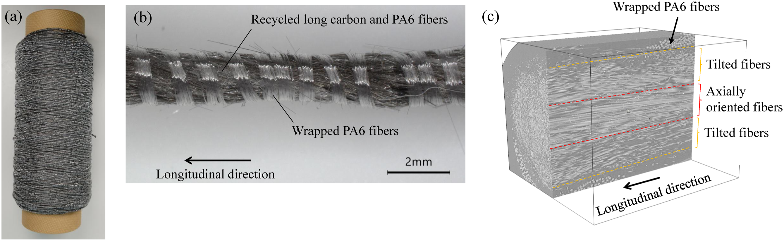
PA6 fibers were used with the recycled carbon fibers to make the spun yarn. The PA6 fibers could have acted as a matrix. However, polyamide 12 (PA12) was added during the filament molding to act as the main matrix. The melting temperature of the PA12 was approximately 175°C, i.e., lower than that of PA6 (225°C). The filament molding temperature was based on the melting temperature of PA12. During the filament molding process, the non-melted PA6 fibers prevented the pull-out failure of the spun yarn by maintaining entanglement.
Recycled carbon fiber-reinforced Polyamide filament
Recycled carbon fiber-reinforced polyamide filament was molded using an in-house filament molding machine (Figure 2). The filament molding machine performed a preliminary impregnation process, whereby PA12 was coated on the spun yarn (“A” in Figure 2). The spun yarn was fed into a resin bath filled with melted PA12 and pulled from the outlet hole located at the bottom. PA12 was impregnated into the spun yarn during the main impregnation process, whereby the spun yarn was pressed against the hot driving rollers (“B” in Figure 2). The PA12 on the surface of the spun yarn was pushed inside repeatedly at each hot roller. Finally, the impregnated spun yarn was shaped so that it had a circular cross-section by passing it through a shape-forming nozzle (“C” in Figure 2). Excess PA12 was removed at the entrance of the shape-forming nozzle. The PA12 was molten near the entrance, but as the temperature decreased toward the exit, it gradually cooled and solidified to stabilize the cross-sectional shape. The molded recycled carbon fiber-reinforced polyamide filament was pulled at a speed of 100 mm/min by a filament winder. The temperatures of the resin bath, the hot rollers, and the shape-forming nozzle were set at 200–210°C. Filament molding machine. (a) Overall view and (b) schematic image. A: Preliminary impregnation process, B: main impregnation process, and C: shape-forming process.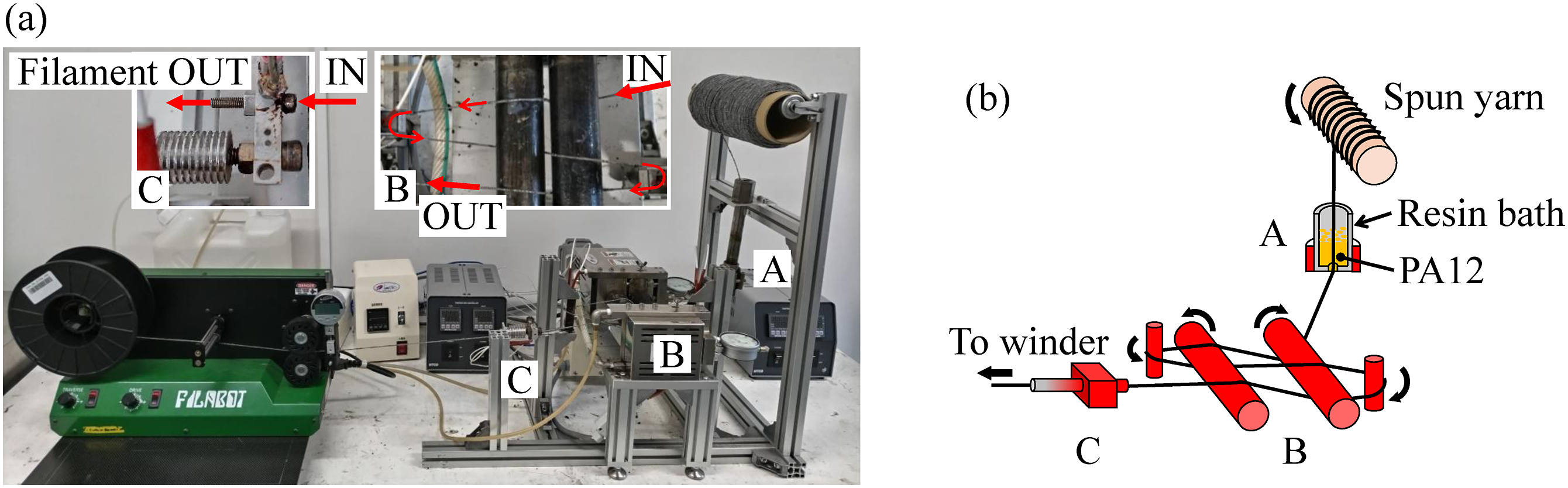
The cross-section of the filament was circular with a diameter of approximately 1.3 mm. A combustion test (ISO 14127:2008) was conducted to determine the fiber volume fraction V f (volume ratio of carbon fiber to PA6 and PA12). The V f was measured by burning five filaments for 2 minutes using a gas burner and measuring their weights before and after the test. The V f of the filament was thereby determined to be approximately 20%.
Three-dimensional Printing
A fused filament fabrication-based 3D printer (Ender-3 S1 Plus, Creality) was used. The nozzle was replaced with the one shown in Figure 3, which was similar to that used for 3D printing a continuous carbon fiber-reinforced plastic.
48
The nozzle features a hole with a diameter of 2 mm inside it and a flat tip to press the filament against the build plate after ejection. The nozzle and build plate temperatures were 255°C and 65°C. The printing speed was 10 mm/s. Nozzle used for three-dimensional printing.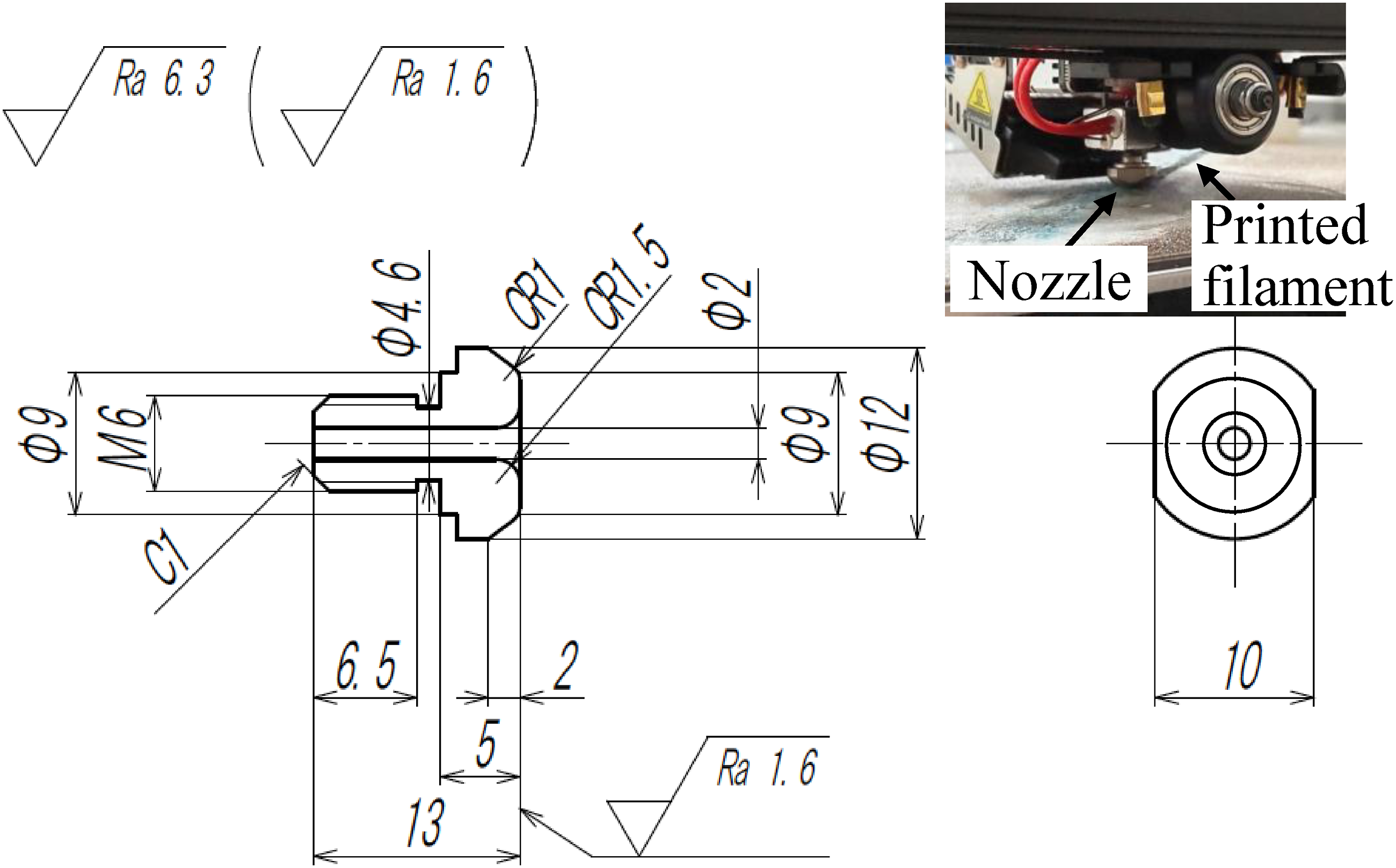
Specimen Preparation
Four types of tensile test specimens were prepared to evaluate the tensile properties and the effects of the 3D printing process: (a) filament, (b) 3D-printed filament, (c) 3D-printed coupon, and (d) hot-pressed 3D-printed coupon.
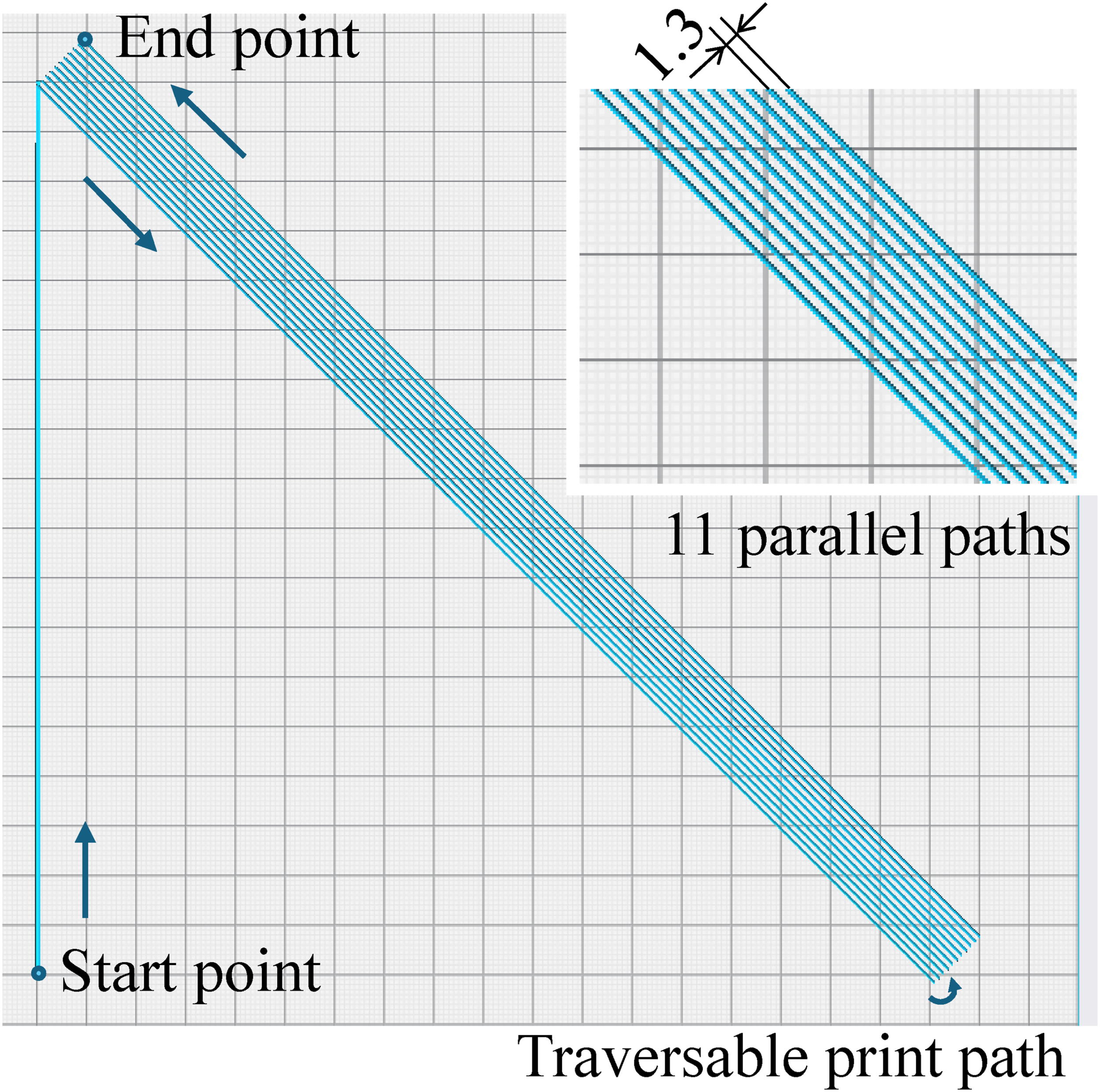
The filament refers to the spun yarn after impregnation with polyamide 12 matrix. The filament was cut to a length of 250 mm for the tensile testing. A tab of glass fiber-reinforced epoxy was glued to each end with epoxy resin (Figure 4(a)). The 3D-printed filament comprised a filament after 3D printing. Only a single line was 3D-printed to evaluate the 3D printing process on the tensile properties of the filament. The 3D-printed filament was cut to a length of 250 mm for the tensile testing. A tab was glued to each end (Figure 4(b)). The 3D-printed coupon was prepared to study the effects of multiple printed lines on the tensile properties. The coupon was 250 mm in length and 15 mm in width (Figure 4(c)). There was one printed layer, and the thickness was approximately 1 mm. The print path was in the longitudinal direction of the coupon, and a total of 11 lines were printed in parallel (Figure 5). The print path was traversable by turning at the edges. The distance between each print path was set to 1.3 mm. It should be noted that net shape manufacturing is also an advantage of 3D printing because it prevents the wastage of materials. Tensile test specimens. (a) filament, (b) 3D-printed filament, (c) 3D-printed coupon, and (d) hot-pressed 3D-printed coupon. Three-dimensional printing path used in the preparation of the coupon specimen.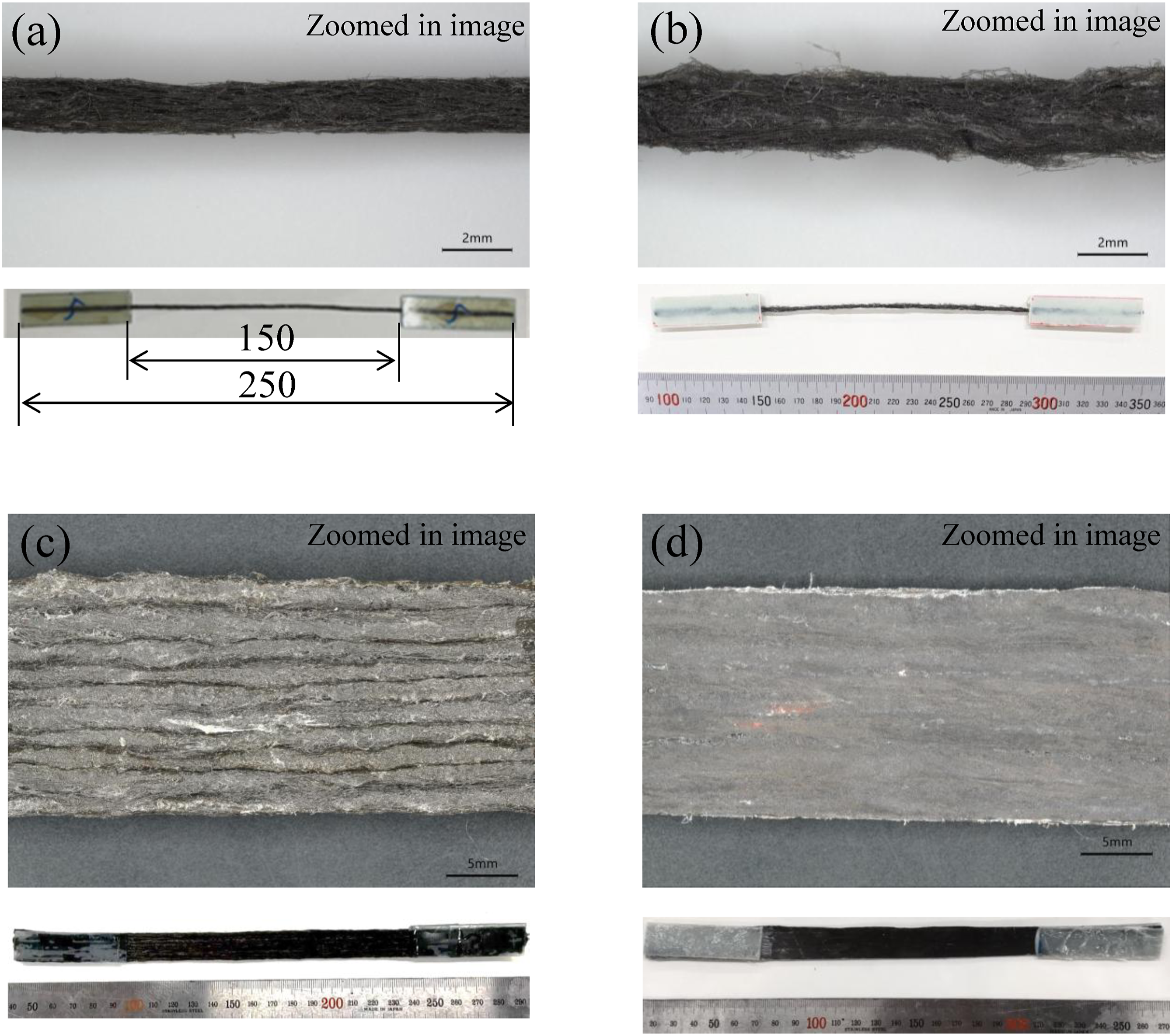
The 3D-printed coupon was hot-pressed to evaluate the effect of the post-consolidation process (Figure 4(d)). The improvement in tensile properties resulting from the post-consolidation process demonstrates the potential advantage of optimizing the 3D printing process. During the hot press treatment, the 3D-printed coupon was placed in a square aluminum frame with inner dimensions of 250 mm × 15 mm × 0.5 mm. The frame containing the coupon was placed between the steel platens of a hot-press machine, and heated to 200°C for 10 min. The thickness of the coupon after pressing was 0.5 mm.
Tensile testing
Tensile tests were performed using a tensile testing machine (AG-IS 150 kN, Shimadzu Corp.) with a 1 mm/min loading speed. The tensile tests were repeated five times on each type of specimen. The stress and strain of the specimens were calculated from the load and displacement of the testing machine. To calculate the tensile stress of the filament, the cross-sectional area was calculated from the average diameter at five different locations of the filament, assuming a circular cross-section. The cross-sectional area of the 3D-printed filament was supposed to be the same as that of the filament. The cross-sectional areas of the 3D-printed and hot-pressed 3D-printed coupons were calculated by multiplying the cross-sectional area of the filament by the total number of parallel print paths. The tensile modulus was calculated based on the slope of the stress-strain diagram between 0.05% and 0.25% strain.
Results and discussion
Cross-sectional observations
Each specimen was filled with a resin. When the resin had cured, it was cut along a plane perpendicular to the longitudinal direction. The cross-sections of each specimen are shown in Figure 6. The filament had an approximately circular cross-section (Figure 6(a)). There was a resin-rich region on the surface. The 3D-printed filament had a flattened cross-section because it was pressed against the build plate by the nozzle tip (Figure 6(b)). It has a bulge in the center since fibers were restricted to rearrange by the spun yarn structure. Surface irregularities from each printing path remained in the 3D-printed coupon (Figure 6(c)). Resin-rich regions were observed at the bottom side due to the oozing out of the resin during printing.
48
The hot-pressed 3D-printed coupon had a flat surface owing to the post-consolidation process (Figure 6(d)). Cross-sections of the four specimens. (a) filament, (b) 3D-printed filament, (c) 3D-printed coupon, and (d) hot-pressed 3D-printed coupon.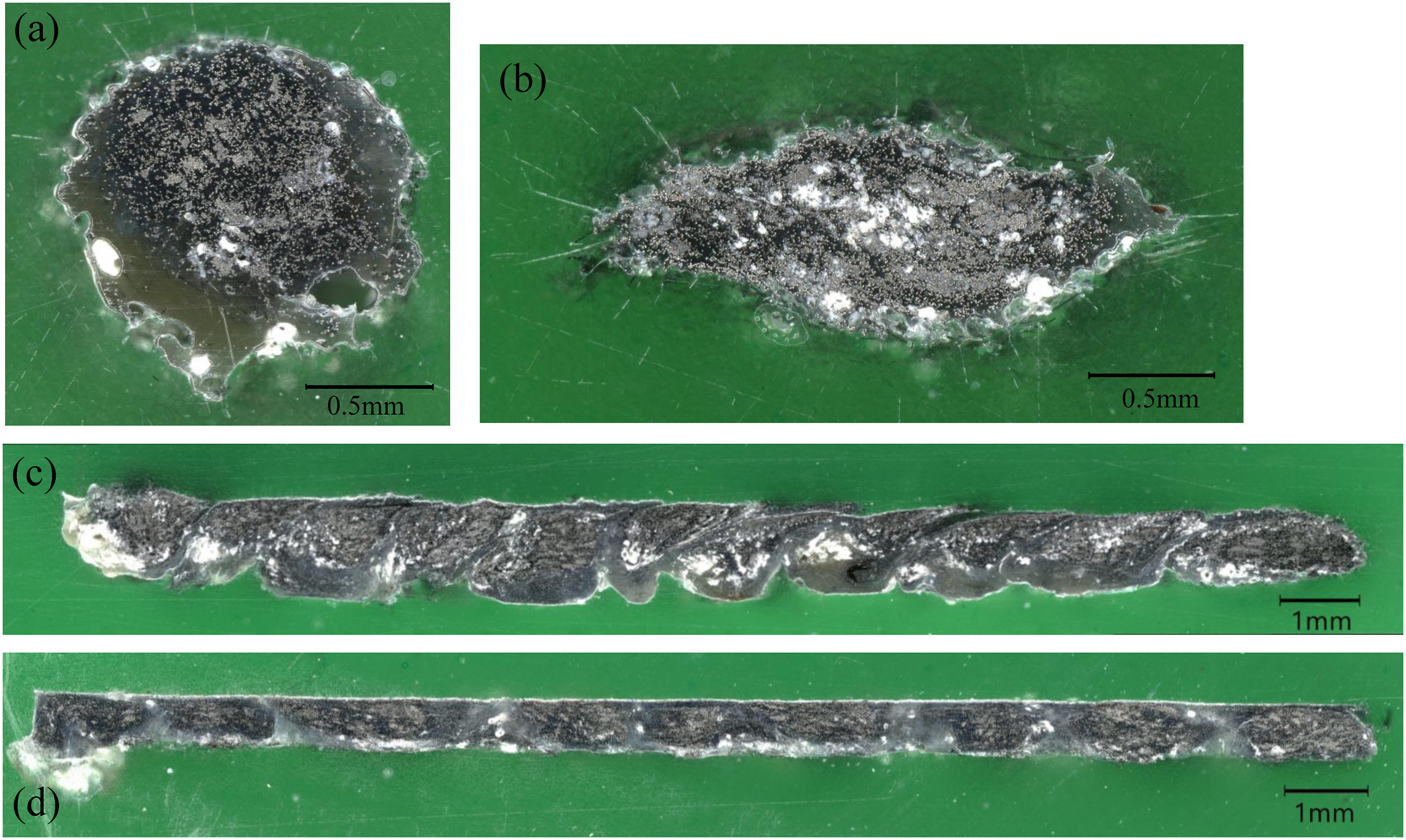
Carbon fiber length
The length of the carbon fibers was expected to reduce due to processing. The lengths of the carbon fibers in the spun yarn were measured using an optical microscope after those were pulled from the spun yarn. The lengths of the carbon fibers in the filament and the 3D-printed coupon were measured after the PA6 and PA12 were removed using a gas burner. In total, 300 carbon fibers were measured for each specimen, and the results are summarized in Figure 7. Cumulative frequencies of the lengths of the carbon fibers.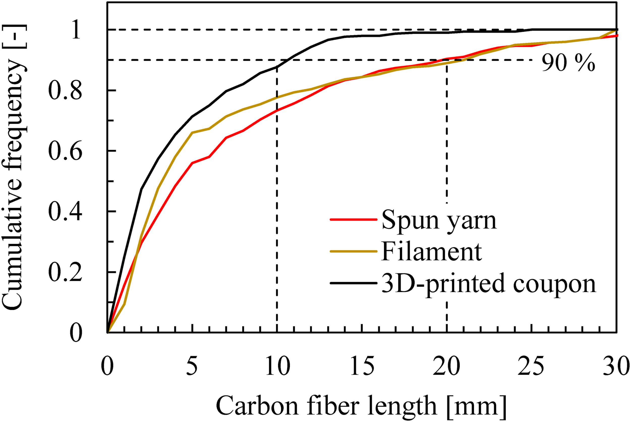
Carbon fibers with a length of approximately 50 mm were used to make the spun yarn, but the fibers were broken during the spun-yarn manufacturing process, resulting in a maximum length of less than 30 mm. The carbon fiber lengths were not significantly changed by the process of molding the spun yarn into the filament. However, they became shorter after 3D printing. This suggests that the tensile properties were adversely affected by the 3D printing process. Moreover, 90% of the carbon fibers in the 3D-printed coupon were 10 mm or less. The filament was bent by 90° and pressed against the print bed by the tip of the nozzle. This damaged the carbon fibers.48–50 The reduction of mechanical properties of continuous carbon fiber-reinforced plastic filaments by the feeding and printing processes during 3D printing was also reported. 50
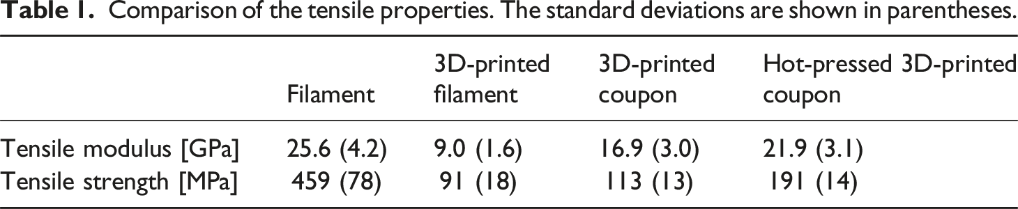
Tensile tests
Typical examples of tensile stress-strain curves are shown in Figure 8. The tensile behaviors were almost linear up to failure for all specimens. The tensile test results are summarized in Figure 8 and Table 1. The filament had the highest tensile modulus and strength. The 3D-printed filament had a lower tensile modulus and strength, demonstrating that the 3D printing process degraded its mechanical properties. This was evidenced by reduced fiber length (Figure 7). The flattening of the filament during 3D printing changed the yarn structure and dispersed the fiber direction (Figure 4(b)), which also adversely affected the tensile properties. Comparison of the tensile properties. (I) Typical examples of tensile stress-strain curves and (II) tensile modulus and strength. (a) filament, (b) 3D-printed filament, (c) 3D-printed coupon, and (d) hot-pressed 3Dprinted coupon. The error bars show the range from the maximum to the minimum value of the measurement results. Comparison of the tensile properties. The standard deviations are shown in parentheses.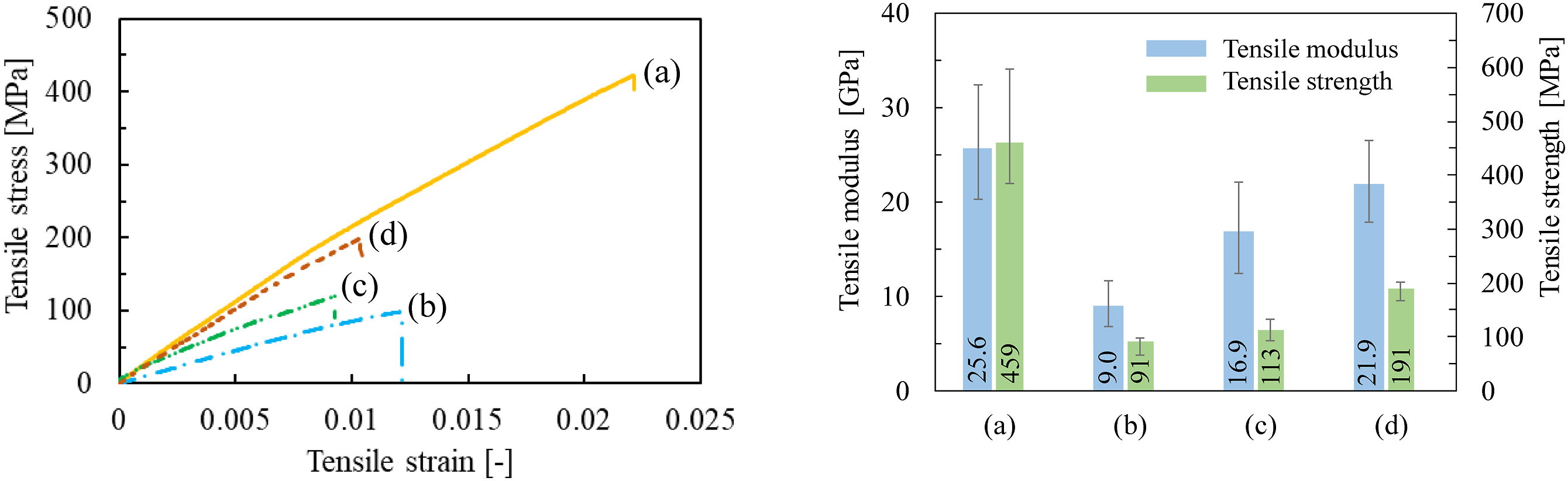
The 3D-printed coupon had an improved tensile modulus and strength than the 3D-printed filament. The 3D-printed filament had a dispersed fiber direction, which caused variability in the modulus and strength along the axial direction. The multiple parallel print paths in the 3D-printed coupon complemented the variability, resulting in improved stiffness and strength. The hot-pressed 3D-printed coupon was stiffer and stronger than the 3D-printed coupon.51,52 The hot press treatment improved impregnation and uniformed the cross-sectional shape, resulting in more uniform stress transmission. The improved interfacial bonding also increased the strength. However, the tensile properties of the 3D-printed coupon did not reach those of the filament, even after the post-consolidation process, owing to the fiber damage and dispersed fiber direction inflicted by the 3D-printing process.
It was reported that the tensile moduli and strengths of a 3D-printed continuous and a milled carbon fiber-reinforced polyamide are approximately 60 GPa and 800 MPa, and 3.8 GPa and 63 MPa, respectively.53,54 In this study, the tensile modulus and strength of the 3D-printed coupon are 16.9 GPa and 113 MPa, respectively, i.e., intermediate between those of polyamides reinforced with continuous or milled carbon fibers. It should be noted that 3D printing techniques for fiber-reinforced plastics are still being developed, and further improvements in the properties of 3D-printed carbon fiber-reinforced plastics are expected.55–58
This paper focused on the tensile properties of the recycled carbon fiber-reinforced composite. Other mechanical and physical properties, such as impact and thermal properties also be expected to improve by aligning the fibers and controlling their orientation.
Fracture surfaces
The specimens after the tensile tests are shown in Figure 9. The fracture surface of the filament was relatively flat, whereas that of the 3D-printed filament was uneven. Increased variation in the fiber direction due to flattening of the filament during 3D printing possibly caused the uneven fracture surface. The fracture surface of the 3D-printed coupon comprised a combination of those of the 3D-printed filament, with irregularities in the cross-section and pulled-out fibers. A relatively flat fracture surface in each print path was produced for the hot-pressed 3D-printed coupon. Long splitting developed, which was similar to the failure mode in a carbon fiber/PA6 composite fabricated from a prepreg sheet.
59
The post-processed results indicate that the mechanical properties of the 3D-printed coupon could be improved by further optimization of the 3D printing process. Fracture surfaces due to tensile loading. (a) filament, (b) 3D-printed filament, (c) 3D-printed coupon, and (d) hot-pressed 3D-printed coupon.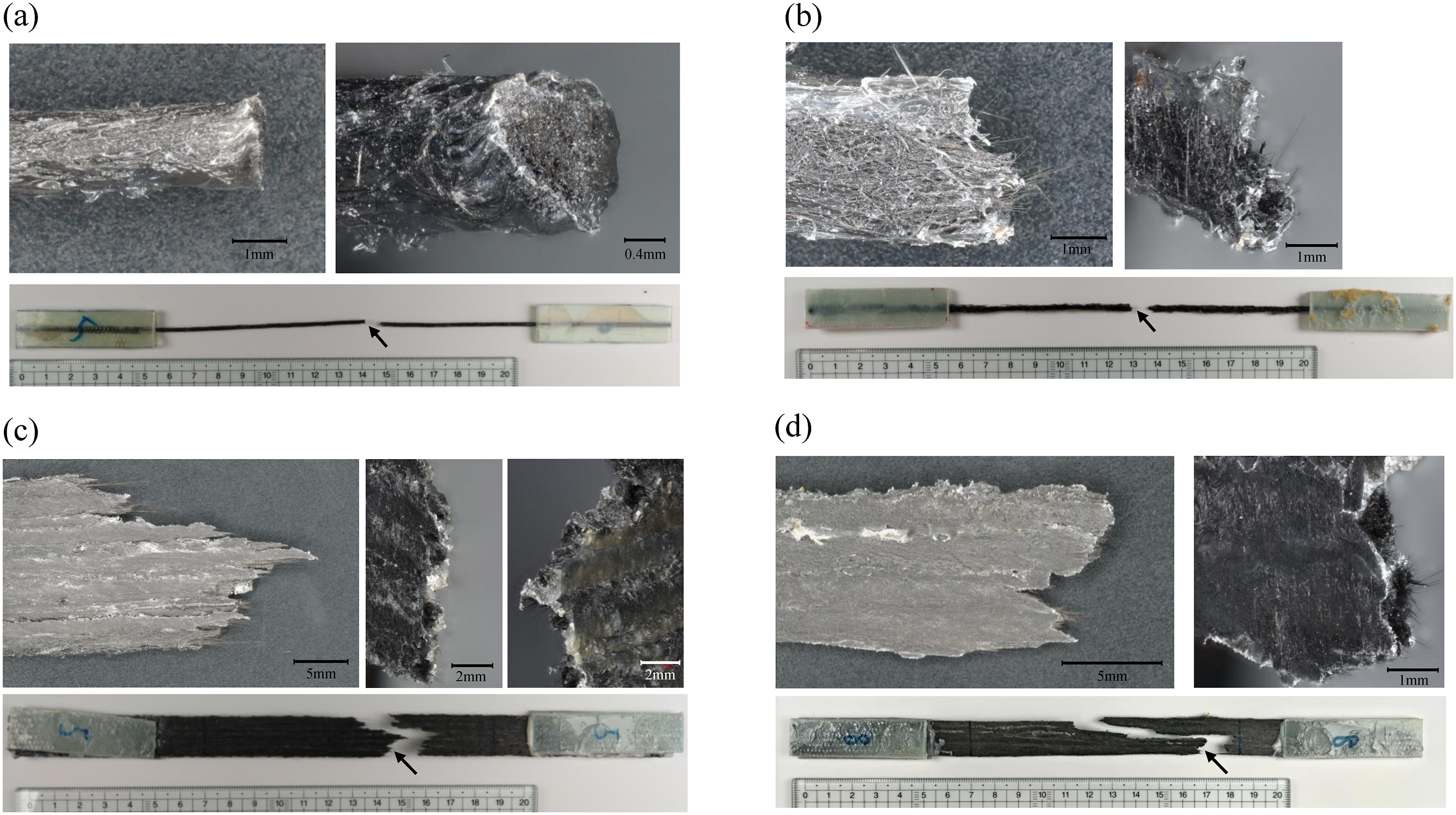
Conclusions
Recycled discontinuous carbon fiber tailoring in a composite by 3D printing was demonstrated. A spun yarn of recycled carbon fibers and PA6 fibers was impregnated with PA12 to form a filament for 3D printing. The filament was 3D-printed unidirectionally, and its tensile properties were determined. The experimental results are summarized as follows. (1) The recycled carbon fibers were aligned almost axially in the 3D-printed filament using the spun yarn technique. The recycled carbon fibers followed the print path. This resulted in favorable mechanical properties in the print direction. (2) The filament had the most favorable tensile properties. The 3D printing process caused fiber damage and dispersed fiber direction, which adversely affected the tensile properties of the 3D-printed filament. Multiplying the filament compensated for the variability in the tensile properties of the 3D-printed filament, which improved the tensile properties of the 3D-printed coupon. (3) Hot-pressing treatment improved the tensile properties of the 3D-printed coupon. Further optimization of the 3D printing process is required to elicit maximum performance from the materials. (4) The 3D-printed recycled discontinuous carbon fiber-reinforced polyamide exhibited tensile properties that were intermediate between those of 3D-printed continuous and milled carbon fiber-reinforced polyamides. 3D printing can be used as a molding technique to effectively use various recycled carbon fibers from continuous to milled forms.
Footnotes
Declaration of conflicting interests
The author(s) declared no potential conflicts of interest with respect to the research, authorship, and/or publication of this article.
Funding
The author(s) received no financial support for the research, authorship, and/or publication of this article.