
Abstract
In this paper, the effects of coupling location on the properties of bending-twist modes are proposed. The static test and modal analysis of the composite plates are investigated. Initial coupling effects are first obtained from the static test of the plates. The frequencies, nodal lines, and the mode shapes are then studied experimentally and numerically. A new method is proposed to quantitatively describe the bending-twist coupling performance of laminates using modal assurance criterion. The results show that the coupling location in the middle coupled plates show good coupling effects at lower order vibrations. These results also show that the effect of coupling stiffness. The conclusions can be considered as a reference to analyze the coupling phenomenon of large composite wind turbine blades.
Introduction
Composite materials have been used in numerous engineering fields, such as aeronautics, wind energy, and automotive engineering. These structures have lower weight, higher strength and stiffness, and better fatigue life. Moreover, the composite structures can be tailored to different needs by using different stacking sequences. There are many coupling deformations which takes advantage of the anisotropy of the materials. The controllability of laminated composite plate is completed by changing the fiber orientation angles and the number of plies and selecting proper composite materials. 1 The bending-torsion coupling (BTC) of beams is mainly considered in the aeronautical and wind energy fields in the literature. Chandra and Chopra 2 proposed an analytical model based on Vlasov theory to take static deformation due to elastic couplings into account. In their work, they applied elastic couplings on the upper and lower of the torsional box, which is part of the internal blade structure. Lobitz 3 proposed realization of BTC through re-orientation of the fibers of the UD material on the spar caps, and they assessed load reduction capabilities as function of the BTC coupling coefficient, of which the values up to 60% of the maximum dictated by material stability concepts, fatigue load reduction of 10–20% was achieved for the coupled blades. Wetzel 4 reported the investigation of the use of off-axis carbon fibers in the all-carbon spar cap of 37-m wind turbine rotor blade to induce twist-flap coupling. Bagherpour 5 accomplished material bend-twist coupling to passively alleviate wind turbine loads by introducing an offset angle on the plies of the unidirectional material over the spar caps, and the bend-twist coupling coefficient distributions along the span are generated with the corresponding ply offset angles. The bending-twist structures such as wind turbine blades can be simplified into box-type cantilever structures, which are composed of upper flanges, lower flanges, and web laminates. Considering that web laminates has no coupling effects, the mechanical equivalent model of bending-twist coupled structures is further simplified only considering the upper and lower flanges as laminates. Many of the researchers have completed relative research about the bend-twist coupling phenomenon of beams or laminates using different static test or vibration-based methods. Cui 6 deduced the necessary and sufficient conditions for composite laminates with extension-shear coupling effect which contribute to the bending-twist structures. Murray 7 presented the experimental verification of a composite FEM by static bending tests of 500 mm ×200 mm BT coupled laminate plates, it was found that the bending and twisting response of samples were linear within the range of applied loads and the sensitivity of laminate thickness and accuracy of ply angles. Cuadrado 8 presented a methodology to obtain a physically more accurate model using experimentally measured modal parameters. Thai 9 illustrated a new tangent shear deformation theory for the static free vibration and buckling analysis of laminated composite and sandwich plates, a weak form for the plates based on ITSDT was derived and solved using isogeometric analysis. Xie 10 gave the first demonstration of the use of a laminated carbon fiber reinforced polymer to create cantilever beams with coupled bending-twisting oscillations for multi-mode energy harvesting applications. For some simulation methods, researchers11–13 provided the numerical studies about the sensitivity analysis for quantifying the influence of uncertain input parameters, which is good method for probabilistic analysis.
In engineering application, the bending-torsion coupling of beams or plates is mainly simplified considering for rotor stability, vibration reduction and flutter issues. Bending-torsion coupling is used to passively twist the blade so that it adapts to wind variations. Walsh 14 illustrated of composite materials for wind turbine blade applications by modeling a wind turbine blade as a simple rectangular beam. Lin and Lai 15 adopted a combined analytical and finite element beam model to examine the factors influence the couplings of wind turbine blades, the results showed that the material, off-axis fibers and coupling positions can provide coupling. Bernard 16 designed bending-torsion coupling laminated beam structure device and conducted static and dynamic analysis to study the influence of each nature of coupling and the associations. Ong and Tsai 17 suggested that the optimal fiber orientations angle relative to the long axis in a composite box beam to produce maximum induced twist is approximately 20°. Thus it is commonplace in the wind turbine industry for carbon fibers to be placed at 20° to test the effects of bend-twist coupling on turbine blade performance. Zhou 18 simplified the blade as the coupling area of laminate beam had an important influence to deformational behavior. The entire beams model is proven to be effective and have greatly contributed to the design of blade structures. The wind turbine was mainly studied as beam type in the above literatures, and there is little research on the composites of non-uniform layup with modal characteristics considering coupling effects.
Based on the vibration method, the effect of coupling plate, scholars and researchers also investigated the relevant parameters. Lobitz and Veers 19 examined the twist angles intended to produce load alleviation using the uniform combined experiment blade; it demonstrated the coupling effects by considering it as several beams. They developed the coupling terms for bend-twist and extension-twist using beam “stress–strain” relations, and assessed that when the tip twist ranged from −3°to 10°for the coupling coefficient varying from −0.8 to 0.8. The definition of coupling coefficient was widely cited. Yoo 20 investigated modal characteristics of a rotating cantilever plate, the effects of the dimensionless angular velocity and the fiber orientation angles were investigated. Nodal lines with the associated mode shape variations are observed. This analysis method was adopted in this paper. Moreover, the principle of nodal lines patterns for the symmetrically stacked plate was illustrated. Maeda 21 presented experimental investigation on the vibrational characteristics of cantilevered laminated plate considering the effect of flexural torsional coupling, the vibrational mode shapes were found to be affected considerably by the coupling stiffness. Sinha 22 modeled the fan blade to determine the natural frequencies of all the fundamental modes of vibration in a physics based analytical model of a composite fan blade under rotating condition, illustrated the camber ratio and elasticity modulus, considered the full coupling of flexural and torsional modes in analytical method. Sinha and Zylka 23 investigated the free vibration characteristics of laminated composite stiffened plates, compared the influence parameters of frequency by experimental and numerical results, which revealed the free vibration behavior of laminated composite stiffened plates for the designing. Baucke and Mittelstedt 24 presented a method for the determination of the buckling loads of symmetrically laminated composites plates under uniaxial compressive load with explicit consideration of bending twisting coupling (BTC), and proposed that the closed form analytical analysis equations were still satisfied in the practical work. According to the literature, most authors have focused coupling effects on off-axis plies design to test the bend-twist behavior qualitatively and most from the static point view. In the next subsection, the coupling will be analyzed from the static point initially. The third part of the paper will explore the coupling effect of coupled plates in dynamic point.
The static experiment set by the end loaded cantilever plates while measuring end deflections and rotations to characterize bend-twist coupling behavior. Two groups of symmetric off-axis orientations 20°coupling plates are fabricated and tested. The modal analysis of the plates is proposed considering the coupling feature. It is observed that the natural frequencies obtained from both the experimental and the finite element methods for these cases are in good agreement. Moreover, the nodal lines and mode shapes are obtained to analyze the coupling features; the modal assurance criterion can quantitatively describe the bending–twist coupling performance of laminates. Further, this study will help in providing knowledge and confidence to the designer for the design of wind turbine blade with bending–twist coupling effects.
Geometric configuration and finite element model
Equations of stiffness
According to the classical laminates theory (CLT) as shown in Figure 1, laminated composite materials can be characterized in terms of their response to mechanical loading, which is associated with a description of the coupling behavior, unique to this type of material, coupling between in plane (i.e., extension or membrane) and out of plane (i.e., bending or flexture) responses when Bij≠0, coupling between in plane shearing and extension when A16 = A26≠0, and coupling between out-of-plane bending and twisting when D16=D26≠0, the equation (1) describes the well-known ABD relation form classical laminate plate theory, it is often expressed using compact notation as equation (2). Hence, the balanced and symmetric stacking sequences, which generally give rise to coupling between bending and twisting, signifying that the elements of the extensional stiffness matrix [A]are simple or specially orthotropic in nature, that is, uncoupled, since A16 = A26=0, the bending-extension stiffness [B]is null, whilst all the elements of the bending stiffness matrix [D]are finite, that is, Dij j≠0. A typical laminated plate (a) Details of lamination (b) Fiber orientation of a lamina.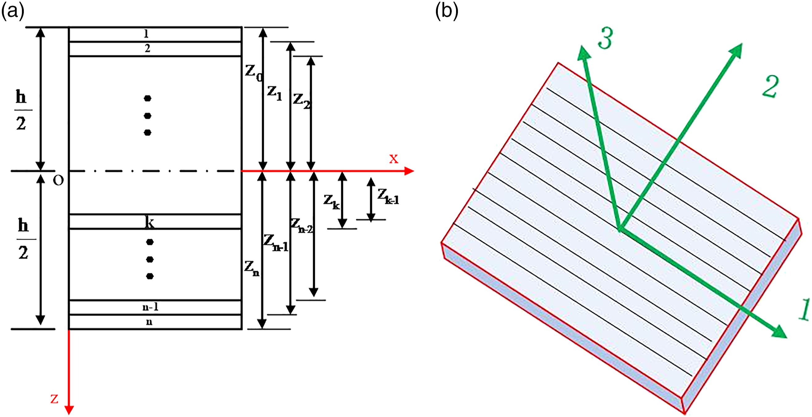
The bending stiffness matrix of a symmetric laminate is equation (3), zk is the position of k-ply lamina in the entire laminates and N is the number of laminates plies.


Fabrication of samples
The dimensions of laminate plates are of 900 mm×200 mm×6 mm. Five different coupling locations along with the length are arranged as shown in Figure 2, with the plates label B to F. The reference plates are made of biaxial glass fabric with two 0° reinforcement laminates, which are glued on the top and bottom of main plates using adhesives. According to the same reinforcement location, the 20° coupling laminate are the same location type. Figure 3 shows this comparison, and it can be seen that the main plates are the same type. Symmetry un-uniform laminates layout. (a) Reference plates without coupling (b) Coupling plates. Comparison of the coupling and no coupling plates laminates layout.

Every plate consists of about 6 mm thickness main layers and 2 mm thick reinforcement layers. The coupling layers stick to the upper and lower symmetrical location, which are cut from the unidirectional fabric plate, with different locations of main plates. These designs provide bend-twist coupling characterization for five plates with different coupling locations.
The main laminated composite plates in experimental study are prepared using vacuum assisted resin infusion method for 48h. The materials used for fabricating the plates are biaxial glass fiber cloth. Final laminates are prepared and the average thickness is 6±0.1 mm. The ±45° biaxial fabric laminates are about 10 layers of glass fiber cloth. The reinforced layers are also manufactured using the same technology to ensure the same process as the main plates. The unidirectional fiber polymers are used to manufacture the plates of coupling location. There are two sizes of plates as shown in Figure 4, the specimen size of 500 mm×300 mm is for fiber orientation 20° and the size of 400 mm×220 mm is for fiber orientation 0°, which can be cut two pieces for each main plate, so the proper size of reinforced plates are retained as the size. After that the reinforced layers stick to the plate using adhesive (WD3135/WD3134) according to the different location as in Figure 3. Cutting size of reinforcement plate.
The vacuum assisted resin infusion technology (VARIT) is completed in the laboratory. The reinforcement specimens were manufactured using the following procedure are shown in Figure 4. The binding material was prepared by adding 75% epoxy resin and 25% harder, the room temperature is 28°C. For fabrication of the plates, the unidirectional glass fiber is cut into required dimension as in Figure 4 and the lamination starts. The plastic sheet is placed on the clean and flat glass table using sealing tape for mold releasing on the bottom, the layer of fiber, the peel ply, flow medium and another plastic sheet are placed in required sequence. The top plastic sheet is much bigger than the bottom one, and the sealing tape is pressed by the roller in all the stage so that there is no gap. Then the VARIT procedure can be done by starting the vacuuming motor.
The stages of fabrication of the reinforcement plates are given in Figure 5. After that the reinforcement plate can be cut into the size of Figure 4. The same orientation coupling plates are placed on the top and bottom of the main plate using adhesive. (a) Cutting of the unidirectional glass fiber, (b) plastic sheet using sealing tape, (c) placing of the fiber and peel ply, (d) put flow medium on peel ply and releasing plastic sheet, (e)weight of the gel coat (epoxy resin and harder), (f) vacuum the system, and (g) demold the peel ply. The stages of fabrication of coupling location plates.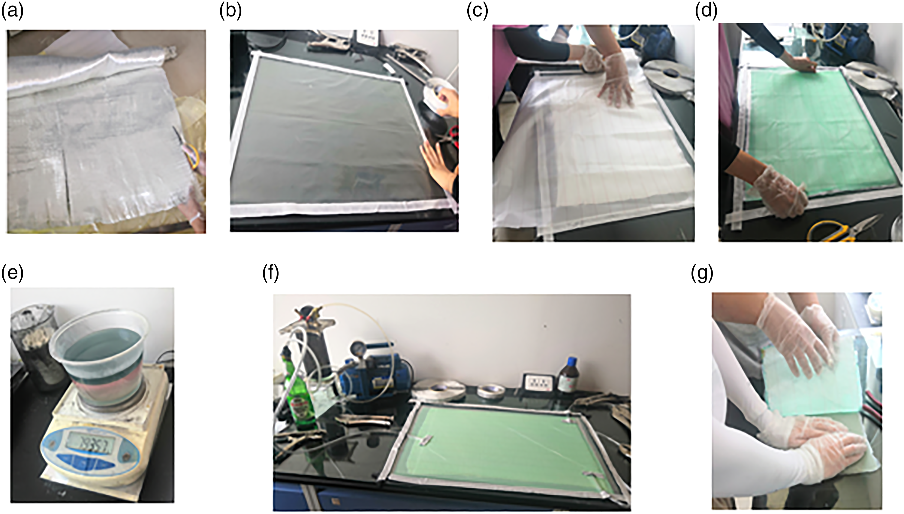
Cross section of the coupon specimen for tensile test.

Material properties of two kinds of glass/epoxy laminated composite.

Static investigation
In order to test the effects of bend-twist coupling, the static test is first completed as Figure 6, the specimen is fixed on the small vibrating table using four screw bolts and nuts. It can be considered as fixed boundary condition. The plate is in a clamp-free configuration. The single point load is applied along the geometric center axis on the upper surface, at the tip of plate (Figure 6). The weight and hook are applied on the point. The mass for the hook is 188 g and 200 g for one weight. So the point load is added step-by-step, and the displacements of plates are retained by the Digital Image Correlation dynamic displacement test system (HPQN-X). Fifteen nodes of two sides are tested for comparison. Static test rig of rectangular coupled plates.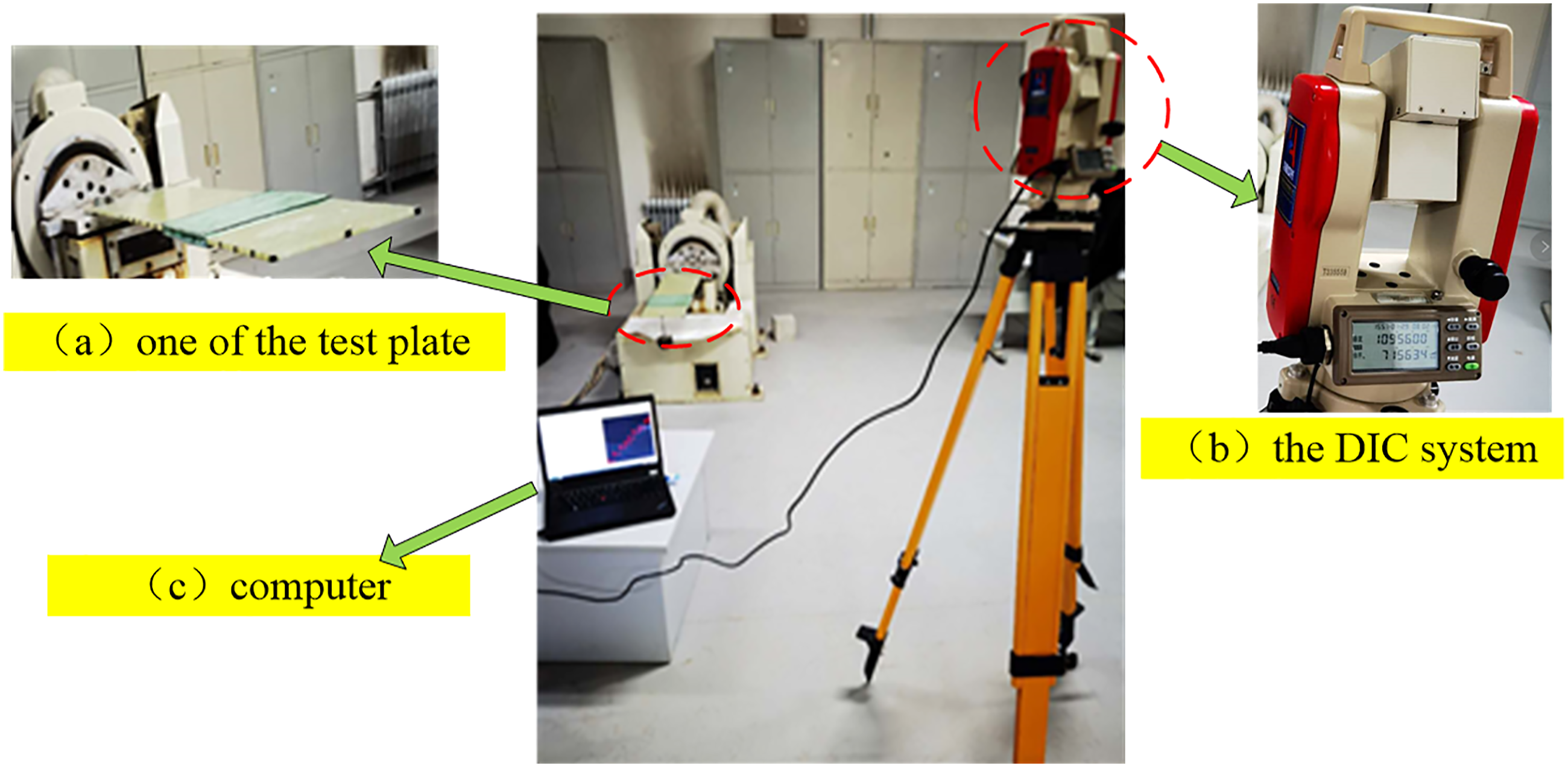
For linear elastic result, the load is given step by step, and the maximum load is 3.88 N with one hook and three weights. The first load is the hook of 188 g. Then the load is increased by 200 g each with one weights. And the test nodes are 4 mm interval for each side by the Number 1 to 15 and 1′ to 15’ Figure 7. Test nodes of static test.
The vertical displacements for the middle centerline OM of the laminate can be obtained using the average deflection of the nodes on two sides. The displacements of the centerline are considered as the bending for the plate. For the twist, the torsion angle can be retained from the vertical deflection of the two sides.
As can be seen in Figure 8, it demonstrates the out-of-plane deflection at the two sides of the laminate plates. The maximum displacement of z direction is the F20 plate, with the off-axis ply fiber orientation is 20°at the end of plate. But the displacement of E20 plate is much bigger in middle part of the plate. Comparison of the z direction displacement of plates.
For the orthogonal ply laminate, the relationship between the stiffness coefficient are D11≫D12 and D11≫D66. So the bending stiffness can mainly depend on the coefficient D11. Obviously, the value of D11 for orientation 0° is bigger than 20°, so the whole bending stiffness coupled with 0°ply laminate plate is relatively large. The displacements for these two kinds of orientation verified this.
It is difficult to define the section twist, so the bending displacements are calculated as average rotation, estimated by the displacements of two points (Figure 7). Taking point 1 and point 1′ as an example, as shown in equation (5)
The results in Figure 9 show that the twist deflection of the two configurations are mostly close to zero. The couplings of different location in the plates generate quite a low twist, whereas the configuration of 20° off-axis ply generates much higher results. From the Figure 9a, the values of twist displacements are mostly lower than 0.00032, this may be due to the test error of the equipment. According to Figure 9b, the coupling plates show different coupling effects of the various locations. It is worth mentioning that the twist of E20 plate is higher in the middle part near the location of coupling. The same trend is retained to the plate of D20, C20, and F20. The maximum twist displacements are mostly near the coupling position of the plate. Comparison of the twist displacement of plates. Model of bend-twist coupling beam.

The coupling coefficients based on the nodal displacement method are shown in Figure 10 with the blade considered as cantilever beam model. The blade coordinate system is from the root to the tip in the x direction, the y axis is for the chord direction, and the z axis is perpendicular to the plane xoy. The solid line is the beam model before deformation and the dashed line is the deformation. Comparison of the coupling coefficient of plates.

Free vibration test
In order to test the coupling effects, the modal tests are performed to obtain the natural frequencies of all plates. As shown in Figure 12, the composite plates are clamped on the small vibrating table using four screw bolts and nuts as the static test. The test is carried out with the signal acquisition instrument, accelerometers, impact hammer, and modal software. The accelerometer sensor type is DYTRAN model, of which the mass is about eight g. The measuring points are set symmetrically. Six sensors are installed to measure the acceleration response signal. The excitation is performed by hammer with force transducer at the measuring point of No 1. The direction is perpendicular to the plate and the input signal is considered as a pure bending excitation. The modal deformation is obtained by means of the predefined mesh with 33 points. Here, the first seven mode shapes will be treated. Modal testing assembly.
Numerical modeling
A finite element models are created using software ANSYS. The plates are meshed with shell181 element type. The plate on the xy-plane is six rectangular with un-uniform on the coupling location. The plate thickness is assumed to compose of a composite laminate which may consist of a number of thin layers along with fiber orientations (Figure 13). The same meshing strategy and boundary conditions are used for all plates. The materials of plates are selected as shown in Table 2. The coupling location is varied with different plates, which divided into five equal areas as shown in Figure 13. The stacking sequences of coupling area in each plate is [20°/45°/-45°]s, and the stacking sequences of uncoupled areas is [45°/-45°]s. Finite element model of plate.
The plate dimension is 900 mm×200 mm, the thickness of each plate is obtained from experiments in Figure 3. After verification by different mesh grid, the convergence results are getting together with 50×50 grid for every coupling location and the total mesh of whole plate are 15,000 elements. The quadrilateral isoparametric element is used to mesh the plates. The plate element has 6 degrees of freedom (dof) at each node, that is, translations in the x,y,z directions and rotations about the x,y,z axes. The integration points is chosen as 3 for each layer. The first-order shear-deformation theory of plates is used in the formulation. The boundary conditions of plate are considered as clamped.
And the governing equation for the undamped plate can be expressed as
{x} is the nodal displacement vectors, [M] and [K] are the assembled consistent mass and stiffness matrices, and {F} is the assembled nodal load vector; let 
Using weak form integral, the boundary conditions are obtained as shown below:
According to the clamped boundary,
Results and discussions
In this part, the coupling effects of plates in different locations are investigated from the frequencies and mode shapes. The experimental and simulated results are discussed to access the influence of the different coupling location.
Frequencies
Modal frequencies of reference plates in experiment and FE analysis.

E, experiment result; F, finite element analysis.
Modal frequencies of coupled plates in experiment and FE analysis.

It can be shown from Tables 3 and 4 that there is good agreement between simulation model and experimental results except the higher order natural frequencies. The gap between experimental and simulation results is very small, most ranges are lesser than 3%. The added mass of acceleration sensors and boundary conditions in experiments may increase the gap. For the results of the same configuration, the gap of the frequencies between 0° and 20° is lesser than 5%. This observed results show that the effect of coupling stiffness on the resonance frequencies is only marginal. Due to the increasing of stiffness, higher frequencies are obtained for the off orientation of 20° all the coupling location. But the coupling effects according to the value of resonance frequencies for the laminates are not apparent.
Nodal lines of modes
The mode shapes can be mainly concluded as two types: the bending-dominant mode and twist-dominant mode. The coupling effects can be further explained according to the nodal lines patterns of the coupling plates. Obviously, there is no nodal lines with the first bending mode of the plate. It is well-known that the nodal lines ignoring the coupling effects will be parallel to the edge of the plates. To show the bend-twist effects, the second and third bending-dominant and twist-dominant modes are compared in Figures 14 and 15. The experimental nodal lines are shown in red lines and the numerical results are displayed using the displacement vector sum contour plot. The blue zones in the left of plates which are almost include the red lines are the nodal lines areas according to the finite element modal analysis. The right blue areas are the boundaries of the plates. Nodal lines of bending coupling mode of experimental and finite element model plates. Nodal lines of twist coupling mode of experimental and finite element model plates. Variation of the nodal lines of the simulation bending and twist.

The nodal lines patterns of coupling plates are found to be variant for different coupling location. It can be concluded from the Figure 14, the experimental nodal lines of the second bending modes that coupled in the middle areas show good coupling effects. The typical second bending-dominant modes are in C20, D20, E20 plate. Additionally, the magnitude of this coupling effect could be identified from the slopes between the central axis direction and the vertical nodal lines of the vibrations, especially for the second modes. The slopes of middle part coupling plates are bigger than the other location. Strong coupling effects are presented in E20 plate in the second bending modes.
Comparing the nodal lines of twist-dominant modes in Figure 15, the nodal lines of the twist modes are asymmetric. It is observed that the coupling has a much significant effect in the E20 plate with bigger curvature of the central axis in the twist mode. It can be seen that the twist-bending coupling effect is present on the nodal lines of the E20 plate in the second twist mode. For the third twist mode, the slopes of nodal lines of the middle coupling location show a rather remarkable coupling with bending deformation.
Comparing the numerical and experimental modes, the comparative results of nodal lines trend show similarities with the experimental results. But for the most nodal lines, the locations of experiment are behind the finite element results, especially in the nodal lines of the second bending modes. This is because of the boundary conditions between the two is not identical, the bolted connections are simplified as clamped. In fact, the experimental boundaries are slightly free in rotation. The nodal lines areas of finite element results are varied according to the coupling location. The bending mode areas of B20 is near the tip, while the C20, D20, and E20 are slight offset to the constraint end. This suggests that the degree of coupling effect depends on the coupling location. And the slopes are apparently different, it can be used as qualitative parameters for bending-twist coupling phenomena. With respect to the twist mode areas, the coupling effects are not distinct like the bending mode. This indicates that the bending stiffness is smaller with respect to the twist stiffness at this twist modes. But the blue area of C20 and D20 plate located with the similar shape. It also has same slopes for the nodal lines, the reason is that the mass of coupling area distribution has influence on torsional deformation. On conclusion, the slopes of nodal areas can be thought as a new qualitative index to describe the coupling effects for some modes.
It is observed that the nodal lines of the bending and twist mode are like the experimental results. This can reveal that the 20° ply orientation can change the local coupling rigidity. As described in experimental nodal lines, it can also be concluded that the coupling location changes the nodal lines distribution. It demonstrates local bending coupling intuitively in the plate of E20.
Mode shapes
In this section, the experimental nodes displacements in z direction are organized from the upper and lower sides of the plates to describe the local coupling feature.
The mode shapes of all coupling plates are rearranged in Figure 16a–(d). Clearly from the figures, it is very intuitively shown the bending-dominant shapes and the displacement gaps of the two sides because of the coupling effects. It is obvious that the coupling area occurs continuously for E20 in most middle part of the plate. Figure 16a clearly shows the coupling effect of E20 plate and D20 plate for the second bending mode in the middle location of the plate. Figure 16b shows the third bending mode variation of gaps for C20 and E20. Observed that relatively gaps for coupled C20 plate is also in the middle of plate. Bending and twist mode shape configuration of coupling plate in experiment.
With this method, the shapes of twist-dominant mode in Figures 16(c) and d are compared. Note that the gaps reveal the local deformations. The local coupling position occurs at the middle part of E20 and D20 plate for the twist modes. It is evident that the coupling effect of F20 plate presented in the second twist mode. The reason for this comes from the D16 and D26 terms which represent the flexural-torsional coupling effects in the matrix Dij of equation (3).
Identification matrix
The coupling effect of each plate is obtained significantly which changes the symmetric of the mode configurations. The nodal lines and the shapes can be described qualitatively. The difficulty lay in the quantification of the amount of bending and twist deformation in Eigen mode. The Modal Assurance Criterion (MAC) is usually used to correlate modal deformation between simulation and experiment. The use of this criterion
27
is based on eigenvectors as in the following equations. Φri is eigenvectors from the reference plate and Φci is eigenvectors from the coupling plate.
Identification matrix of B20’s configuration (%).

Identification matrix of C20’s configuration (%).

Identification matrix of D20’s configuration (%).

Identification matrix of E20’s configuration (%).

Identification matrix of F20’s configuration (%).

With the identification matrix, it is easy to determine the component of bending and torsion of reference plate in each mode of coupled plate. The column value of the matrix can be visually to know the proportion of the mode. For the lower order of the bending mode, the coupling location in the middle plate show good coupling effects. For example, in the second bending mode, the diagonal values of C20, D20, and E20 plate are smaller, which reveals that the three plates coupled in the middle location show high coupling effects for the lower modes, and the modes are composed of some order of bending modes, bend–bend or twist–twist local mode types.
Observed the higher-order modes, the coupling phenomena are more complex. For the second twist mode, the three plate also show great coupling effects. The type is bend-twist coupling for the C20 and E20. From the table, the most coupling mode consist of the lower or higher order mode with local bend or local twist. The B20 plate also show good coupling effects in the higher mode.
Conclusions
The aim of the paper was to present a way to describe the bending-twist coupling for symmetric un-uniform composite laminates. The off-axis ply orientation which contributes to coupling effects are deduced by static test and modal analysis. The nodal lines and shapes of coupling plates are first obtained to describe the coupling effects through experimental and numerical investigation.
It has been verified that coupling effect on the resonance frequencies is very marginal. However, the vibrational mode shapes are significantly affected by the coupling stiffness. Moreover, it should be noted that the coupling effect on the mode shapes becomes maximum at the middle coupled plates, especially for the E20 plate. The coupling region has significant influence on nodal lines distribution. The differences in slopes reveal the differences of coupling stiffness, which are tested to better understand the influence of coupling. The identification matrix proposed can be quantified the coupling effects for each plate. This quantitative method can be used to analyze the degree of bend–twist, bend–bend, or twist–twist for different coupled plates accurately. Finally, the Modal Assurance Criterion method allowed to quantify the coupling effects for more accurate and highlighted the fact that static may not be suitable for optimum dynamic coupling. This experimental process highlighted a coupling effects with different locations which can be used to analyze the dynamic coupling design of wind turbine blade.
Footnotes
Acknowledgments
This work is financially supported by the Natural Science Foundation of China (grant no.51675179) and the Fundamental Research Funds for the Central Universities, NCEPU (grant no.2019QN133).
Declaration of conflicting interests
The author(s) declared no potential conflicts of interest with respect to the research, authorship, and/or publication of this article.
Funding
The author(s) received no financial support for the research, authorship, and/or publication of this article.
Data availability
Some or all data, models, or code that support the findings of this study are available from the corresponding author upon reasonable request (list items).