
Abstract
A semi-analytical method for in-plane vibration analysis of a composite laminated annular and sector plate with elastic constraints is presented. The theoretical model is on the basis of a variational method and a multi-segment technique. Displacement variables are expanded by the Jacobian orthogonal polynomial. Boundary conditions and continuity conditions between segments are characterized by penalty parameters. On this basis, a series of numerical examples are given. The results show that the method has good convergence speed and accuracy. Finally, the parametric study of geometric and material parameters is carried out to provide important support for solving the in-plane characteristics of this kind of composite structure.
Keywords
Introduction
With the development of science and technology, the preparation technology and equipment of composite materials have made great progress, so the application prospect of composite materials is also very promising. As a typical lightweight material, fiber laminated material has excellent mechanical properties such as light weight, high strength and so on, so it has been widely used in aerospace, shipping, automobile and other industries. For elastic plate and shell structures, their vibration forms can be divided into two types: one is the transverse vibration formed by bending wave, the other is the in-plane vibration caused by the longitudinal wave. Because of the wavelength, the frequency of transverse vibration is often in the low frequency region, while the frequency of in-plane vibration is often high frequency. The results show that in-plane vibration is very important in some specific high frequency regions. 1 Therefore, the study of in-plane vibration has also attracted extensive attention of scholars.
Park 1 proposed an analytical solution to study the in-plane vibration of the clamped circular plate of uniform thickness with an isotropic material. Wang et al. 2 applied the modified Fourier–Ritz method to examine the free in-plane vibration of orthotropic circular, annular and sector plates with general boundary conditions. Shi et al.3,4 used the generalized Fourier series method to study the in-plane vibration behavior of annular sector plates with elastic boundary supports. Liu et al. 5 extended the differential quadrature hierarchical finite element method (DQHFEM) to study the free in-plane vibration of plates with several planforms. Chen et al. 6 used the isogeometric finite element method for the in-plane vibration analysis of orthotropic quadrilateral plates with general boundary restraints. Yuan et al. 7 proposed an exact analytical solution for free in-plane vibration of sector plates with simply supported radial edges. Bao and Wang8,9 presented a generalized solution procedure to research the in-plane free vibration of rectangular and annular sectorial plates with general boundary conditions. Farag and Pan 10 employed the series superposition method to study the modal characteristics of in-plane vibration of circular plates clamped at the outer edge. Ravari and Forouzan 11 used the separation of the variables to investigate the in-plane frequency of orthotropic circular annular plate with general boundary conditions. Kim et al. 12 proposed an exact solution to study the in-plane natural vibration behaviors of a circular plate with outer edge restrained elastically. Lyu et al. 13 presented an accurate solution for the in-plane vibration analysis of rotating circular panels with general edge restraints.
The above has summarized the in-plane vibration research of the annular plate, annular sector plate, circular sector plate, circular plate and other structures. It can be found that the current in-plane vibration research is rare for the fiber-laminated structure, and almost no relevant research results have been published for the composite structure studied in this paper. The research on vibration of composite laminated annular and sector plate is mainly concerned with the out-of-plane vibration or three-dimensional vibration. Khare and Mittal 14 applied the three-dimensional finite element method to study the free vibration of thick laminated circular and annular plates. Based on the simplified plate theory, Zhang et al. 15 presented the vibration characteristics of composite laminated annular sector plate, circular sector plate, annular plate and circular plate with various elastic boundary conditions. Malekzadeh 16 proposed an accurate and efficient solution procedure to study the free vibration of thick laminated annular sector plates on the basis of three-dimensional elasticity theory. In the framework of the first-order shear deformation plate theory, Belardi et al.17,18 discussed free vibration characteristics of composite circular plates undergoing transversal loads according to Ritz method.
As mentioned above, it is the in-plane analysis that is very important in the early design for the composite laminated annular sector plate, circular sector plate, annular plate and circular plate. This paper is mainly to develop a unified solution for in-plane vibration analysis of composite laminated annular and sector plate with elastic constraints. A variational method and a multi-segment partitioning technique are introduced for the theoretical model of plates based on the first-order shear deformation shell theory, where the latter was originally developed by the author and coworkers for the dynamic analysis of composite laminated doubly-curved shells of revolution.19,20 The displacement components are expanded by Jacobian orthogonal polynomials. Numerical examples are presented for composite laminated annular sector plate, circular sector plate, annular plate and circular plate subjected to different boundary conditions, geometric parameters and materials.
Theoretical formulations
A composite laminated annular sector and annular plate in Figure 1 is studied. The parameters are expressed in polar coordinates (r, θ, z), located in the middle of the plates. In such a coordinate system, r represents the radial direction, θ the circumferential direction and z the thickness direction. The inner diameter, outer diameter and thickness are indicated by symbols R0, R1 and h. For a sector plate, the circumferential angle is expressed as ϕ, while for an annular plate, the circumferential angle ϕ is equal to 2π. Note here that when R0 is equal to 0, the annular sector plate and annular plate will degenerate into circular sector plate and circular plate. The included angle between the material coordinate of the kth layer and the r-axis of the plate is denoted by
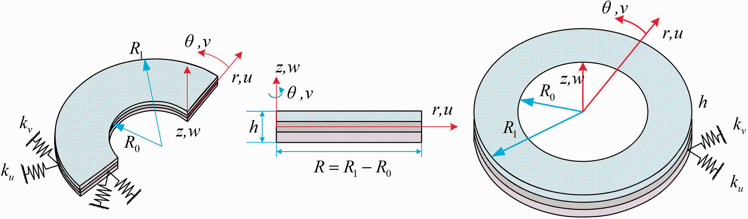
Coordinate system and symbol notations of annular sector and annular plate with general boundary condition.
The theoretical model of the composite laminated annular sector and annular plate can be solved by the variational method and multi-segment technique proposed by the literature.19,20 Under the theoretical framework of this method, general boundary conditions can be easily obtained by setting boundary penalty parameters. For conscience, the modeling procedure will not be shown here in detail.
Because it needs truncating in the radial direction and circumferential direction, it is necessary to expand the displacement function into the superposition form of two-dimensional Jacobian orthogonal polynomials. For the composite laminated annular plate, because of the symmetry in the circumferential direction, it can be expanded by Fourier series, so only the displacement function in radial direction needs to be expanded by a mixed series of one-dimensional Jacobian orthogonal polynomials and Fourier series. Correspondingly, the specific expressions of their displacement functions are as follows
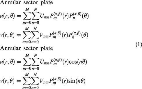
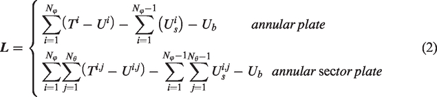
Similarly, for the annular sector plate, the multi-segment technique needs to be carried out along the r direction and θ direction, and the numbers of segments are Lr and Lθ, respectively. For the annular plate, only segment along the r direction and the number of segments is Lr. Therefore, the energy functional of composite laminated annular sector plate and composite laminated annular plate are, respectively, expressed as follows
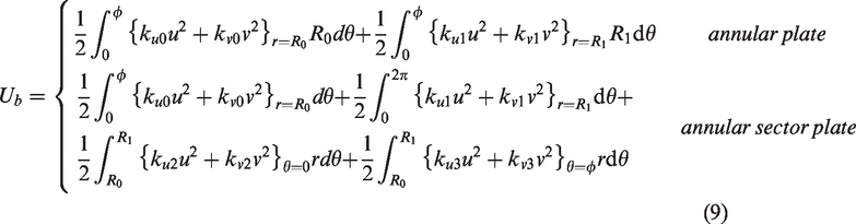
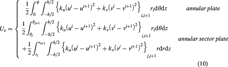
The following kinetic energy functions will be developed in segments. The strain energy and kinetic energy of plate segments are defined as
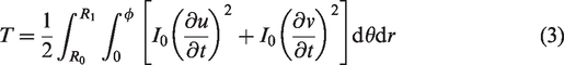
The strain energy for the plate segment is


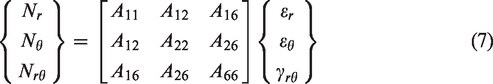
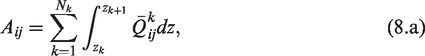
The force and moment resultants relations to the strains and change of curvatures are


The boundary energy stored in the boundary of composite laminated plate can be described as
It must be explained here that the above symbols
Substituting equations (3) to (10) and (1) into equation (2), one obtains the discretized equations of motion for a composite laminated annular sector and annular plate

Numerical results and discussion
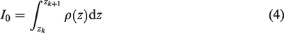
The proposed approach is general and applicable to the in-plane problem of composite laminated annular sector plate and annular sector plate. To validate its accuracy and utility first, numerical results are shown for composite laminated annular sector plate and annular sector plate with various boundary conditions. The vibration results of the composite laminated plate are given in the dimensionless form, expressed as

In the above modeling process, through equations (1) and (2), it can be found that the calculation accuracy of this method strongly depends on the selection of initial calculation parameters, so the first step is to carry out the parametric research. Figure 2 shows the convergence relationship between the calculation results and the number of segments, where m and n are used to indicate a specified mode that has m radial and n circumferential waves in the mode shapes. Geometric parameters and materials are defined as follows: annular sector plate: h = 0.1 m, R0=1 m, R1=3 m, ϕ = π/2; annular plate: h = 0.1 m, R0=1 m, R1=3 m, ϕ = 2π; E1=150 GPa, E2=10 GPa, G12=5 GPa, G13=5 GPa, G23=6 GPa, ρ = 1500 kg/m3, [0°/90°/0°/90°]. The abscissa parameters in the figure are defined as follows:
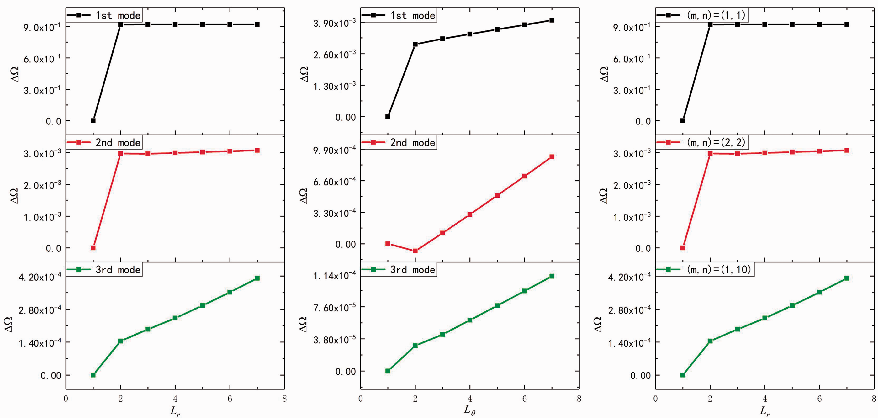
Convergence of frequency results of sector and annular plate with different segment number.
Next, the influence of Jacobian parameter selection on the calculation results is studied. Figure 3 shows the relative error of the calculation results under different Jacobian parameters. The error function is defined as follows:
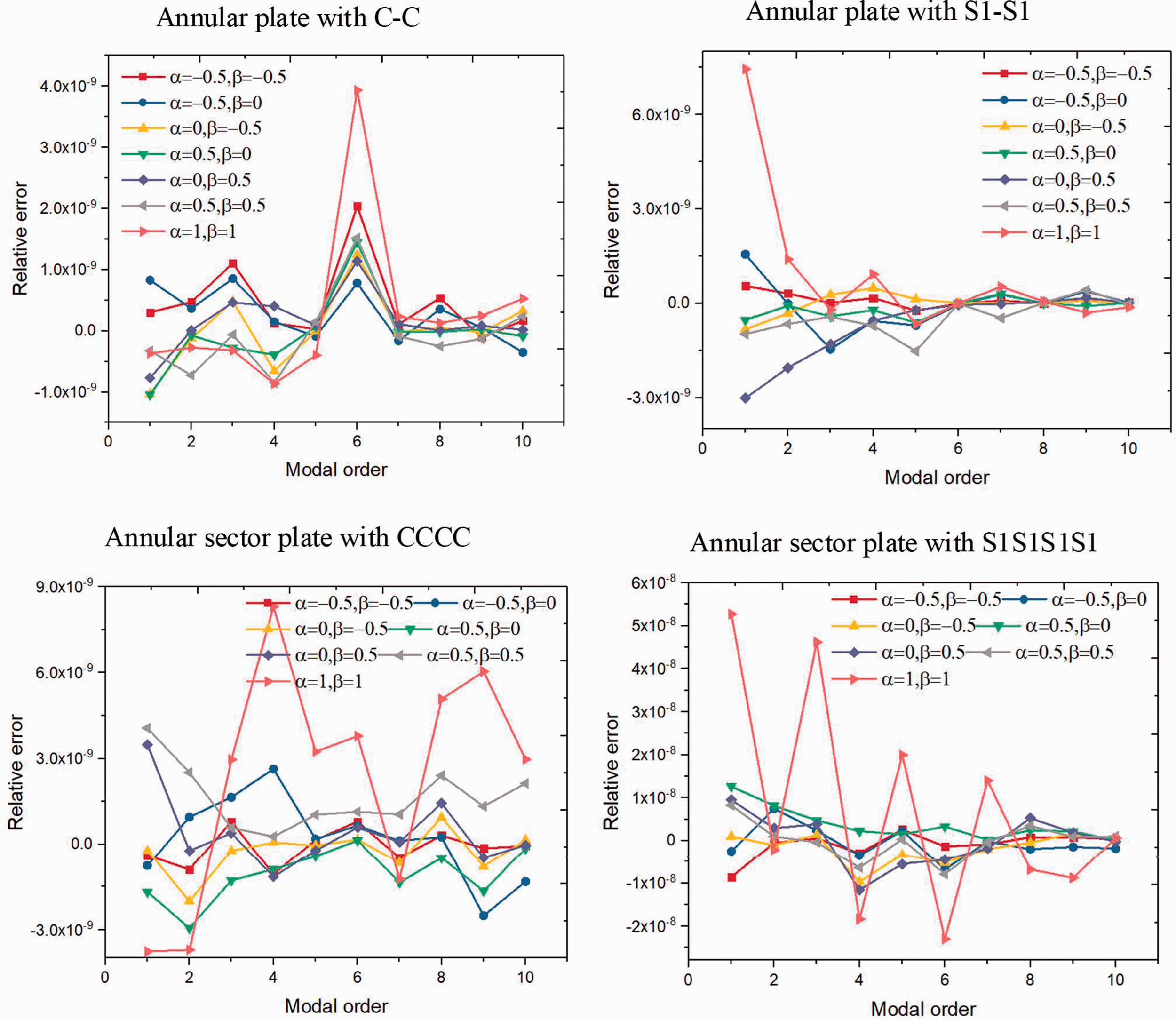
Relative calculation error of annular and sector plate with different Jacobian coefficients.
Next, the influence of the number of expansion terms of orthogonal polynomials on the calculation results is studied. The calculation is given in Figure 4. The boundary condition is the clamped case, and the geometric and material parameters are consistent with Figure 2. The number of expansion items (M or N) is defined as 2, 4, 6, 8, 10. From Figure 4, with the increase of the truncation value (M or N), the calculation result converges rapidly. When the truncation value exceeds 6, it can be found that the calculation result hardly changes. Therefore, in the previous and subsequent examples, the size of all truncation values is set to 8.
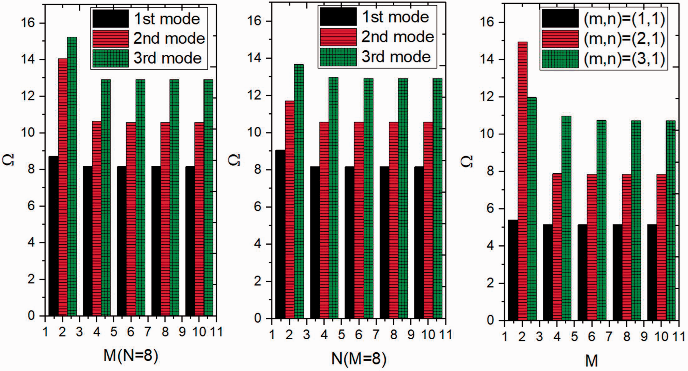
Convergence of frequency results of annular and sector plate with different number of terms of Jacobian orthogonal polynomials.
As described above, the boundary condition and the continuity condition between segments are guaranteed by the penalty function, so it is necessary to study its convergence. Figure 5 shows the convergence of the boundary penalty parameters and the coupling penalty parameters between segments for the calculation results. The geometric and material parameters are consistent with Figure 2. For the study of boundary penalty parameters, regardless of the structural form, only one type of penalty parameter is changed from 0 to 1016, and the other type of penalty parameter is infinite. The remaining edge conditions are all clamped constraints. For the coupling penalty parameter between segments, its variation law is the same as the boundary penalty parameter, and the boundary condition of the structure is defined as the fully clamped constraint boundary condition. It can be seen from Figure 5 that with the increase of penalty parameters, the calculation result converges rapidly. When the penalty parameter value exceeds 1014, the calculation result has hardly changed. Therefore, it is proved that the previous definition of boundary conditions is correct. In addition, three types of elastic boundary conditions are defined here as follows: Elastic boundary conditions 1(E1): ku=109, kv=1014 N/m for r=constants or θ=constants; Elastic boundary conditions 2(E2): ku=1014, kv=109 N/m for r=constants or θ=constants; Elastic boundary conditions 3 (E3): ku=109, kv=109 N/m for r=constants or θ=constants.
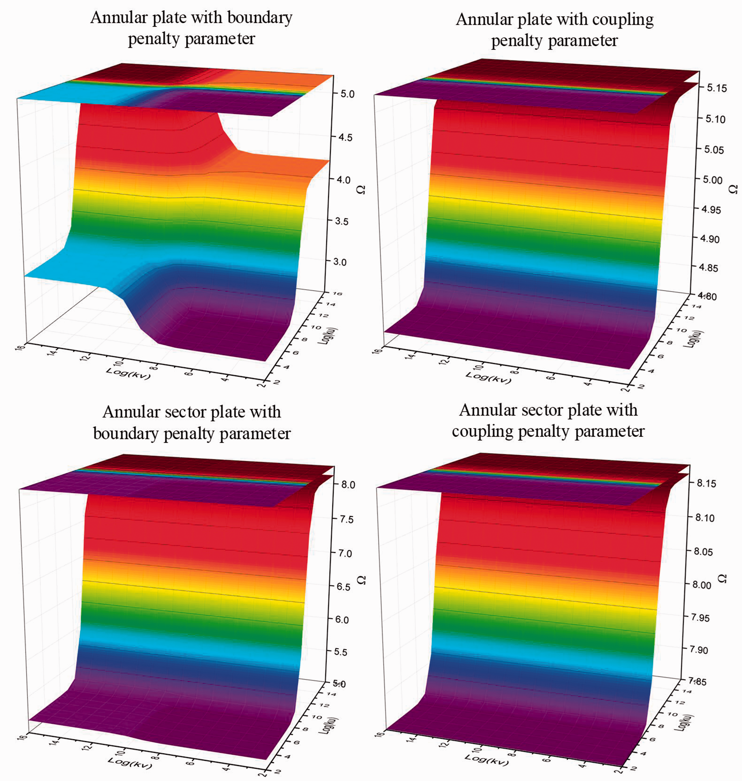
Convergence of frequency results of annular and sector plate with different penalty parameters.
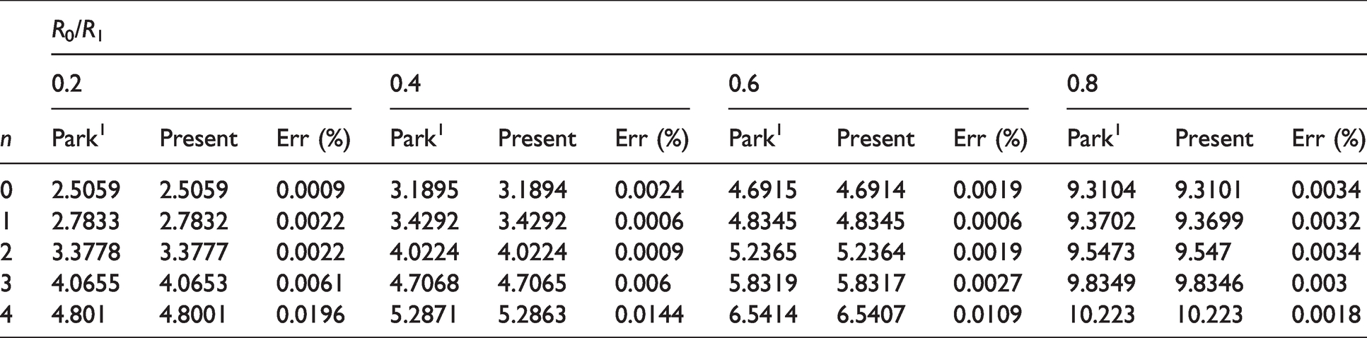
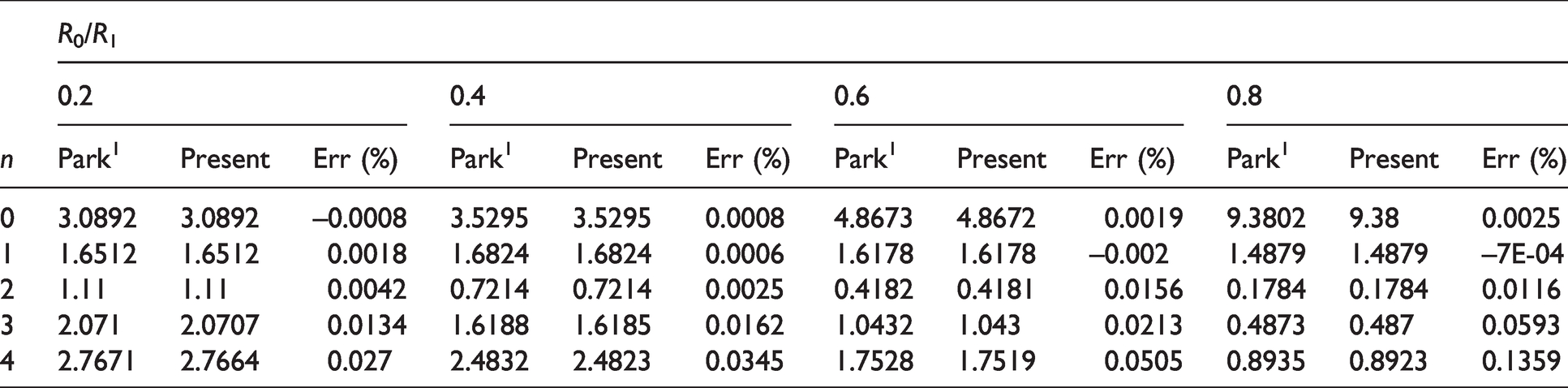
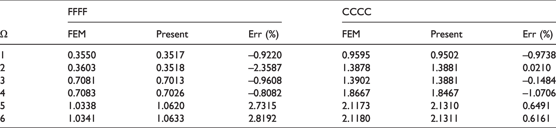
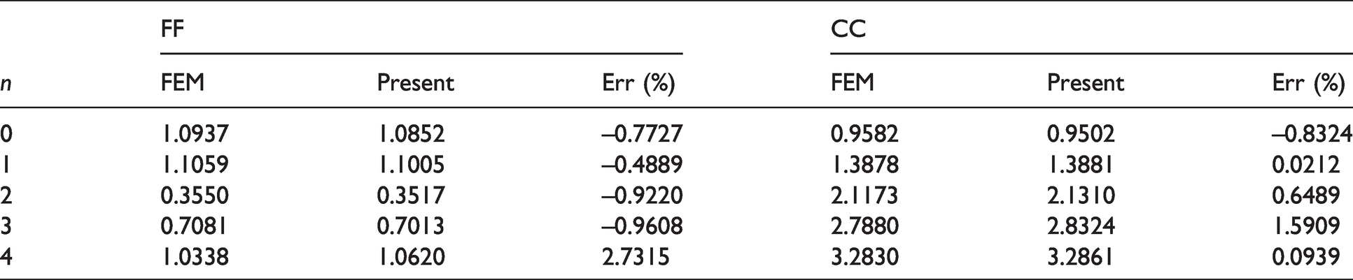
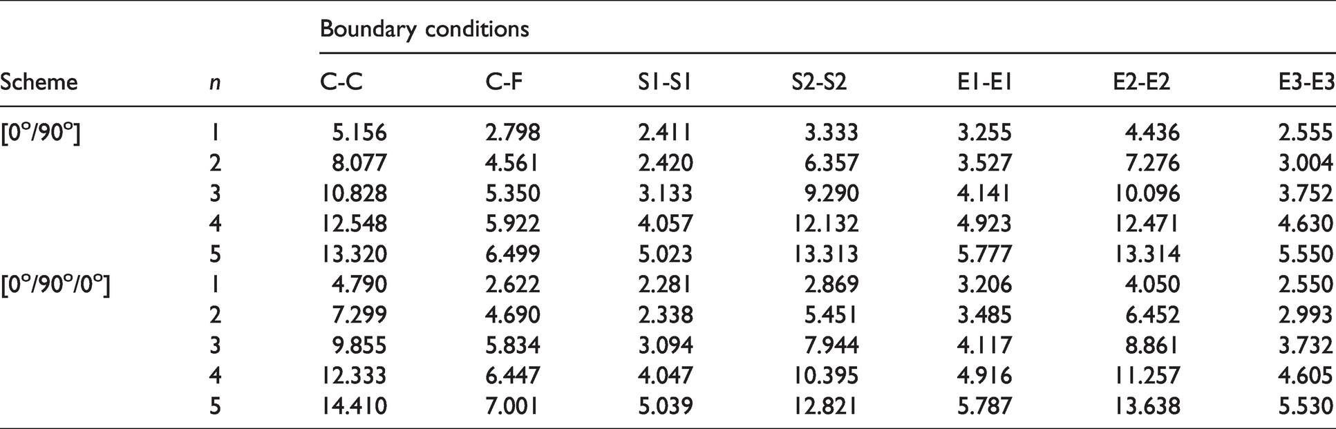
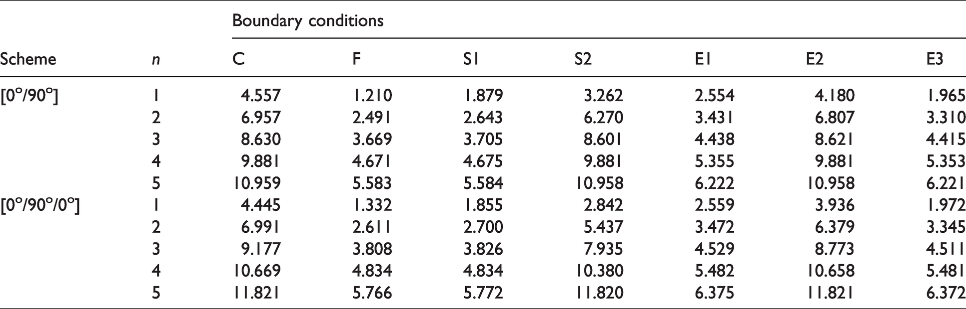
Next, the correctness of the calculation code is studied. Tables 1 to Table 4 show the comparative analysis between the prediction results of this method and the calculation results in the literature. Tables 1 and 2 show the first six frequency parameters of the annular sector plate with CCCC boundary conditions. Geometric and material parameters are defined as follows: h = 0.005 m, R0=0.5 m, R1=1 m; E1=200 GPa, E2=200 GPa, G12= E1/2(1+μ12), G13=G23=G12, ρ = 7800 kg/m3. The reference data 3 are from Ritz method. Tables 3 and 4 show the calculation results of the first five circumferential waves of the annular plate with CC and FF boundary conditions, respectively. Geometric and material parameters are defined as follows: h = 0.005 m, R0=0.2 m, R1=1 m; E1=210 GPa, E2=210 GPa, G12= E1/2(1+μ12), G13=G23=G12, ρ = 7800 kg/m3. The reference results 4 of Fourier series method are also given in the above tables. Tables 5 and 6 show the frequency parameters of annular sector plate with θ1=90 and annular plate of a consistent fiber scheme [0°/90°], where the results obtained by FEM are also presented for validation. The geometric and material parameters are given as: h = 0.1 m, R0=1 m, R1=3 m; E1=150 GPa, E2=10 GPa, G12= 6 GPa, G13 =G12, G23=5 GPa, ρ = 1500 kg/m3, μ12=0.25. Through the comparison of Tables 1 to 6, it can be found that the predicted results are in good agreement with the reference results regardless of the boundary conditions and geometric parameters of the plate.
Comparisons of frequencies of annular sector plate under CCCC boundary.
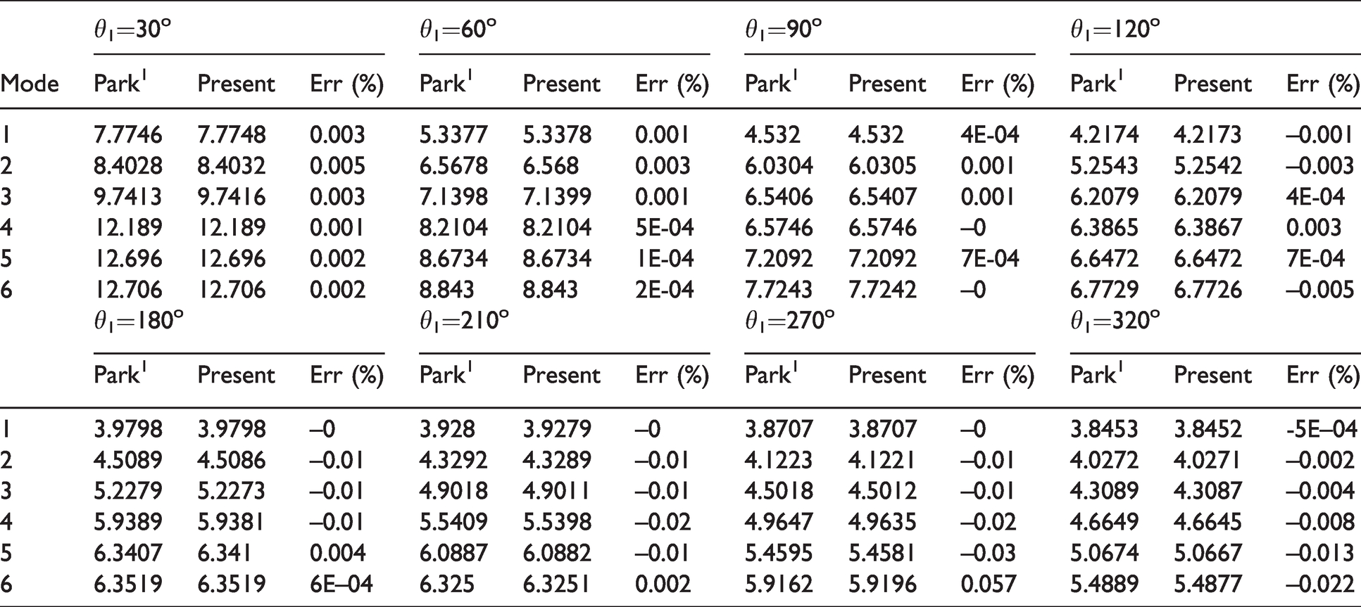
Comparisons of frequencies of annular sector plate under FFFF boundary.
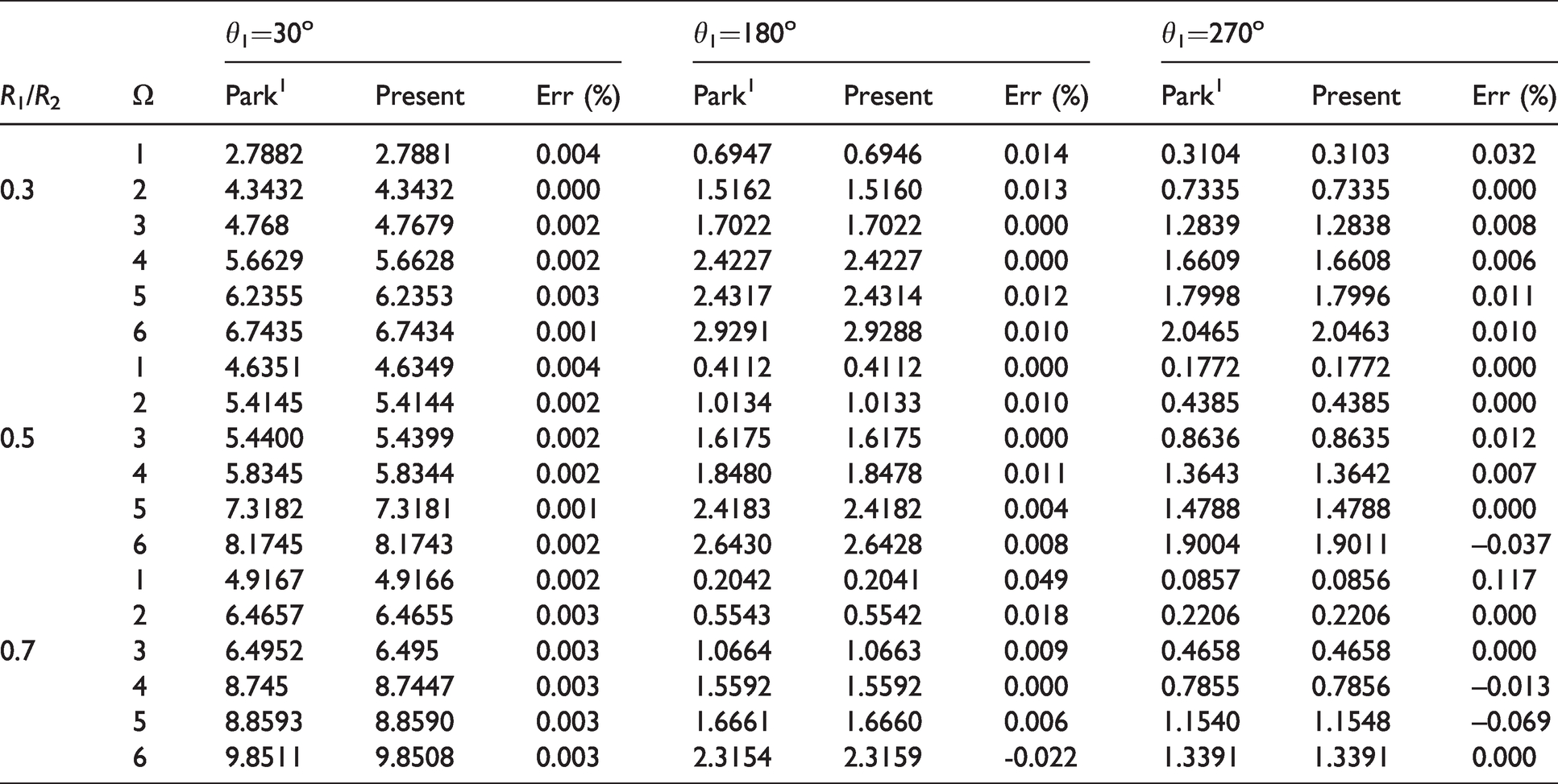
Comparisons of frequencies of annular plate under CC boundary.
Comparisons of frequencies of annular plate under FF boundary.
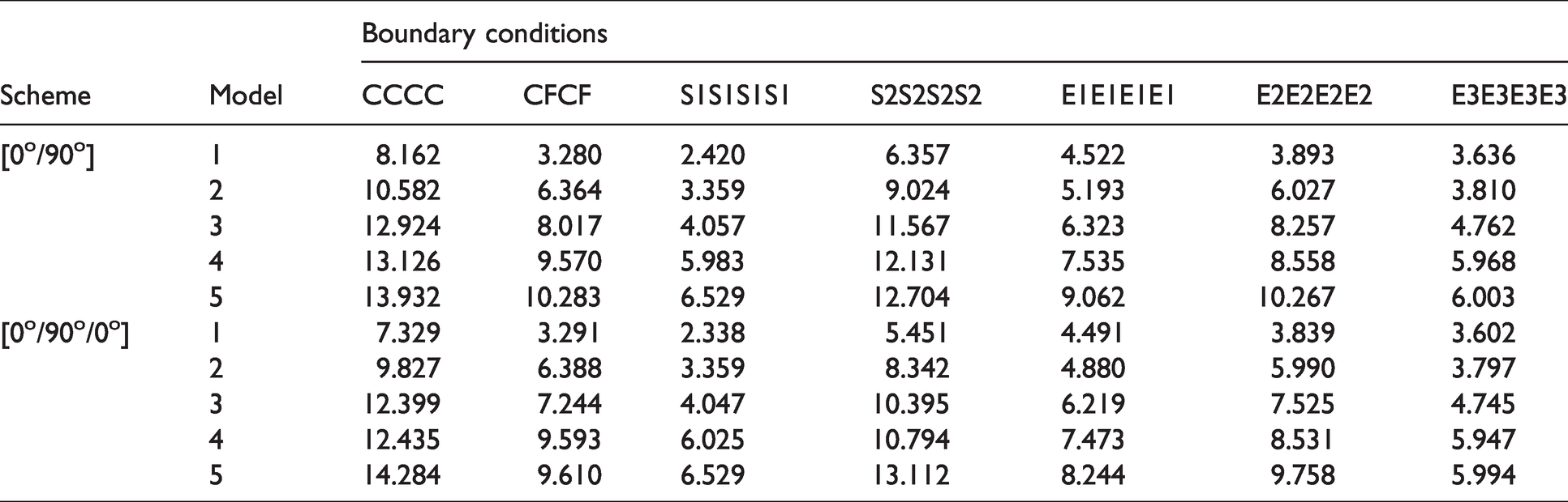
Comparisons of frequencies of annular sector plate with θ1=90 and scheme [0°/90°].
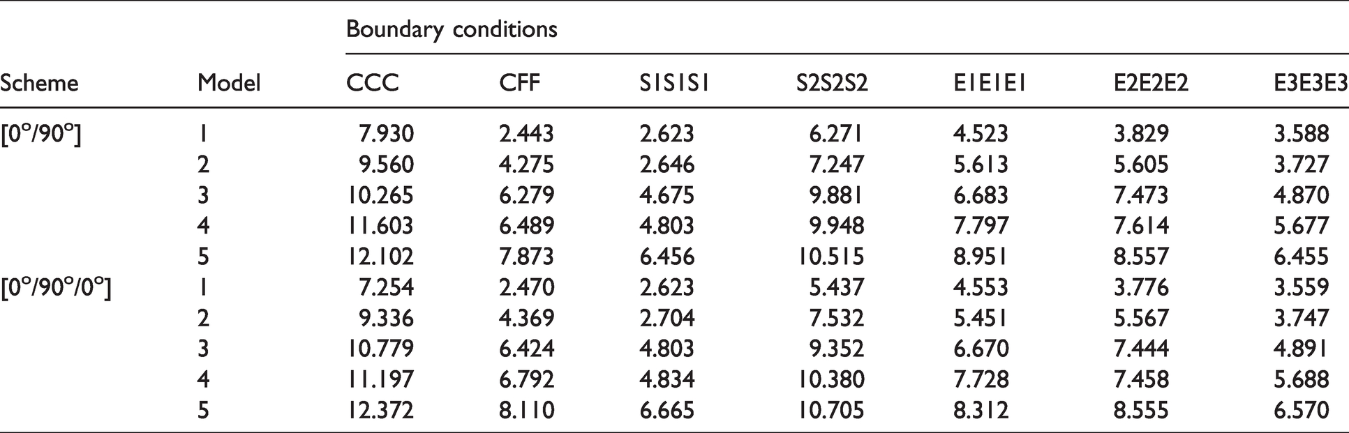
Comparisons of frequencies of annular plate with scheme [0°/90°].
As described above, the research on in-plane vibration characteristics of composite structures in this paper is very rare. Therefore, the first six frequency parameters of composite laminated annular sector plate, circular sector plate, annular plate and circular plate are given in Tables 7 to 10, respectively. The parameters are consistent with Figure 2 except for the fiber scheme. The boundary conditions contain four types of classical boundary conditions and three types of elastic boundary conditions. In addition, in order to provide readers a clearer understanding, some classical in-plane vibration modes are shown in Figures 6 and 7. It can be seen from the above tables that the larger the boundary stiffness coefficient is, the larger the frequency parameter. The above results can provide benchmark data for other scholars in this field.
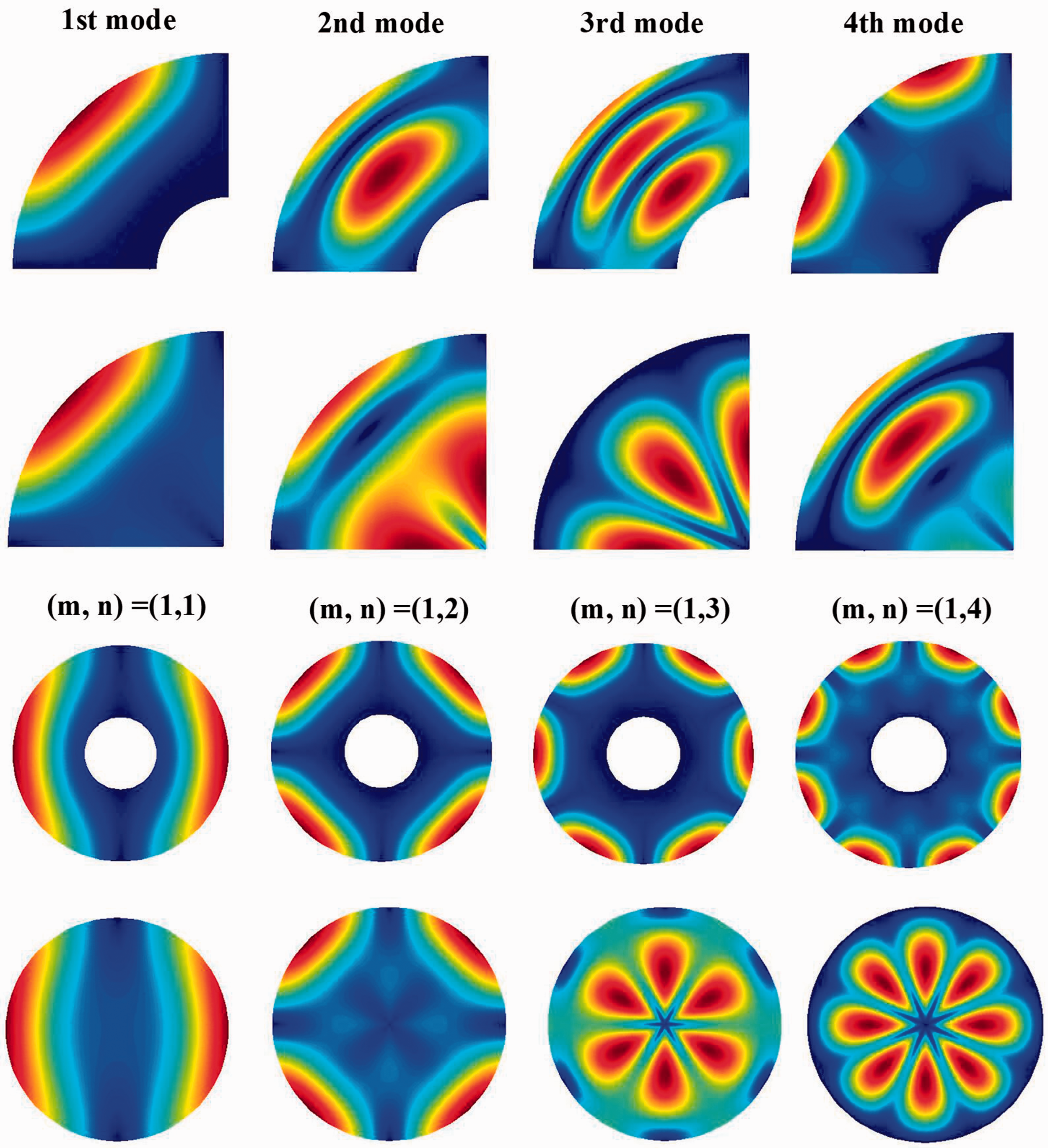
Some mode shapes of sector and annular plate with S2 boundary.
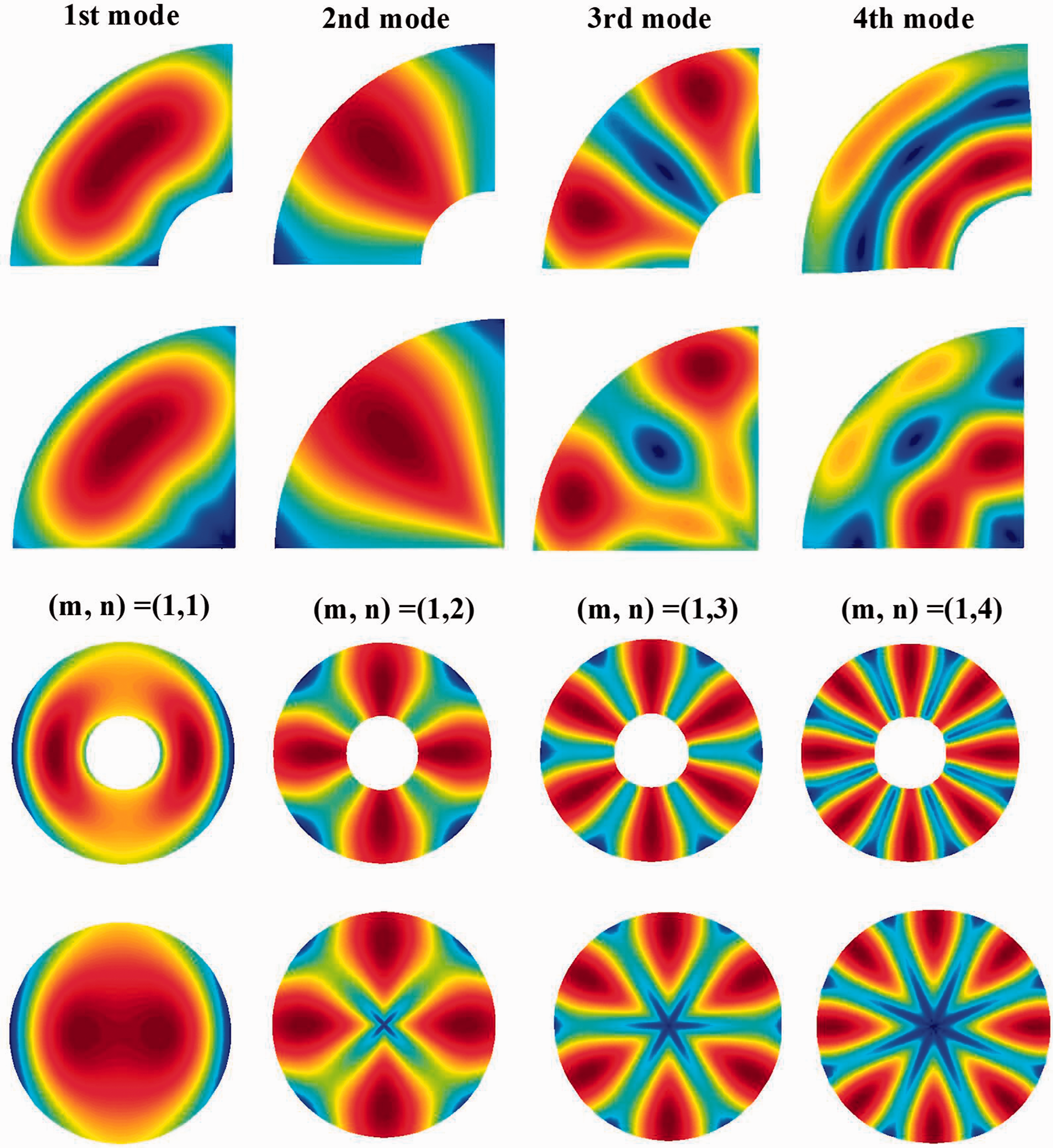
Some mode shapes of sector and annular plate with E3 boundary.
The first five dimensionless frequencies of annular sector plate with various boundary conditions.
The first five dimensionless frequencies of circular sector plate with various boundary conditions.
The first five circumferential (m = 1) dimensionless frequencies of annular plate with various boundary conditions.
The first five circumferential (m = 1) dimensionless frequencies of circular plate with various boundary conditions.
Next, further parameter research will be carried out. Figure 8 shows the first three frequency parameters of the annular sector plates under different radial ratio parameters and boundary conditions. Similarly, the calculation results of the annular plate are shown in Figure 9. The material parameters are consistent with Figure 2, and the radial ratio parameter R1/R0 changes from 2 to 8. It can be seen from Figure 9, regardless of the structure form and boundary conditions, the frequency parameter decreases rapidly with the increase of the radial ratio parameter, because the frequency parameter decreases with the increase of the radial ratio parameter and the increase of the mass matrix.
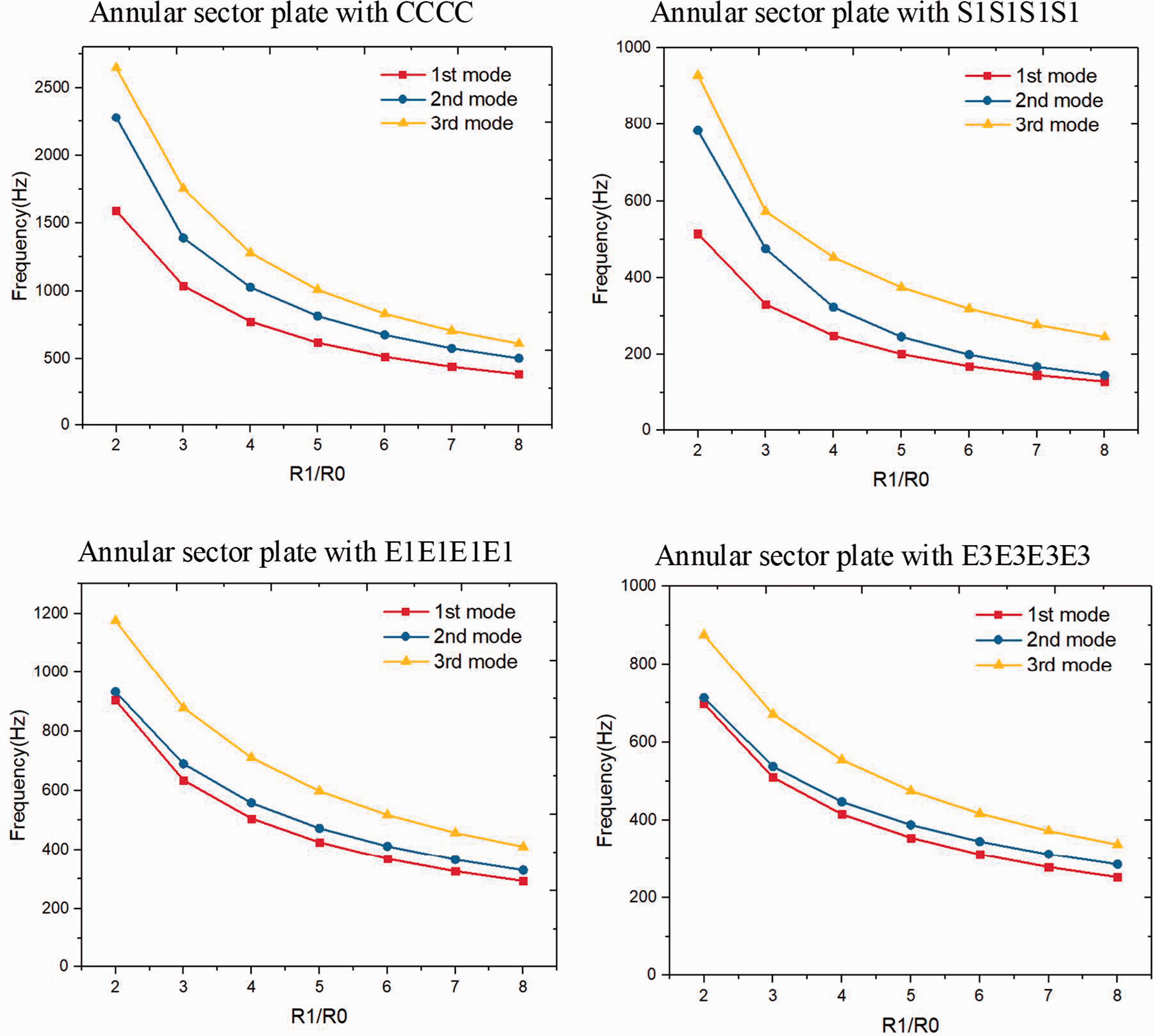
Variations of frequencies of annular sector plates under different boundary condition with respect to various radial ratio R1/R0.
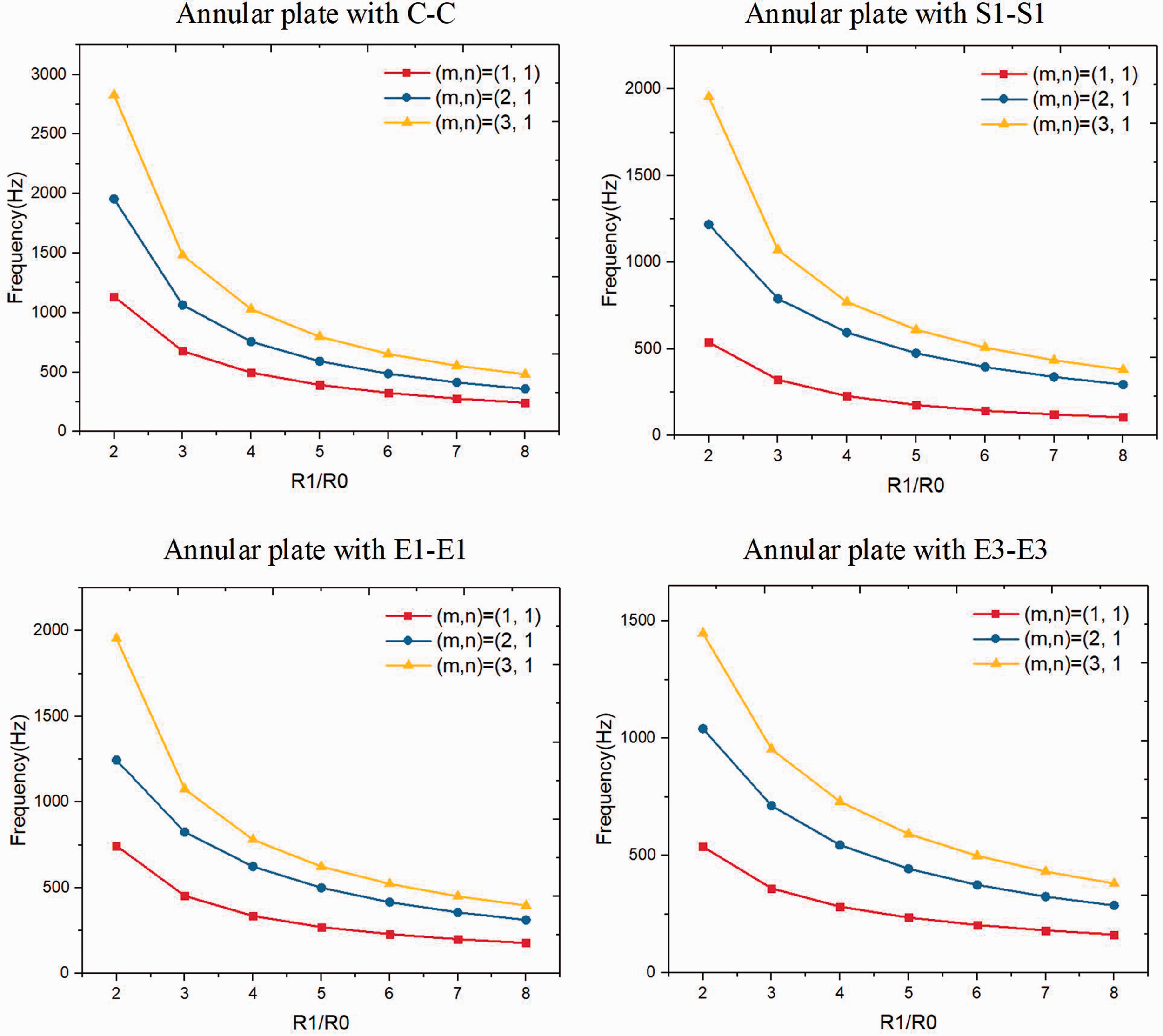
Variations of frequencies of annular plates under different boundary conditions with respect to various radial ratio R1/R0.
Finally, the influence mechanism of fiber angle
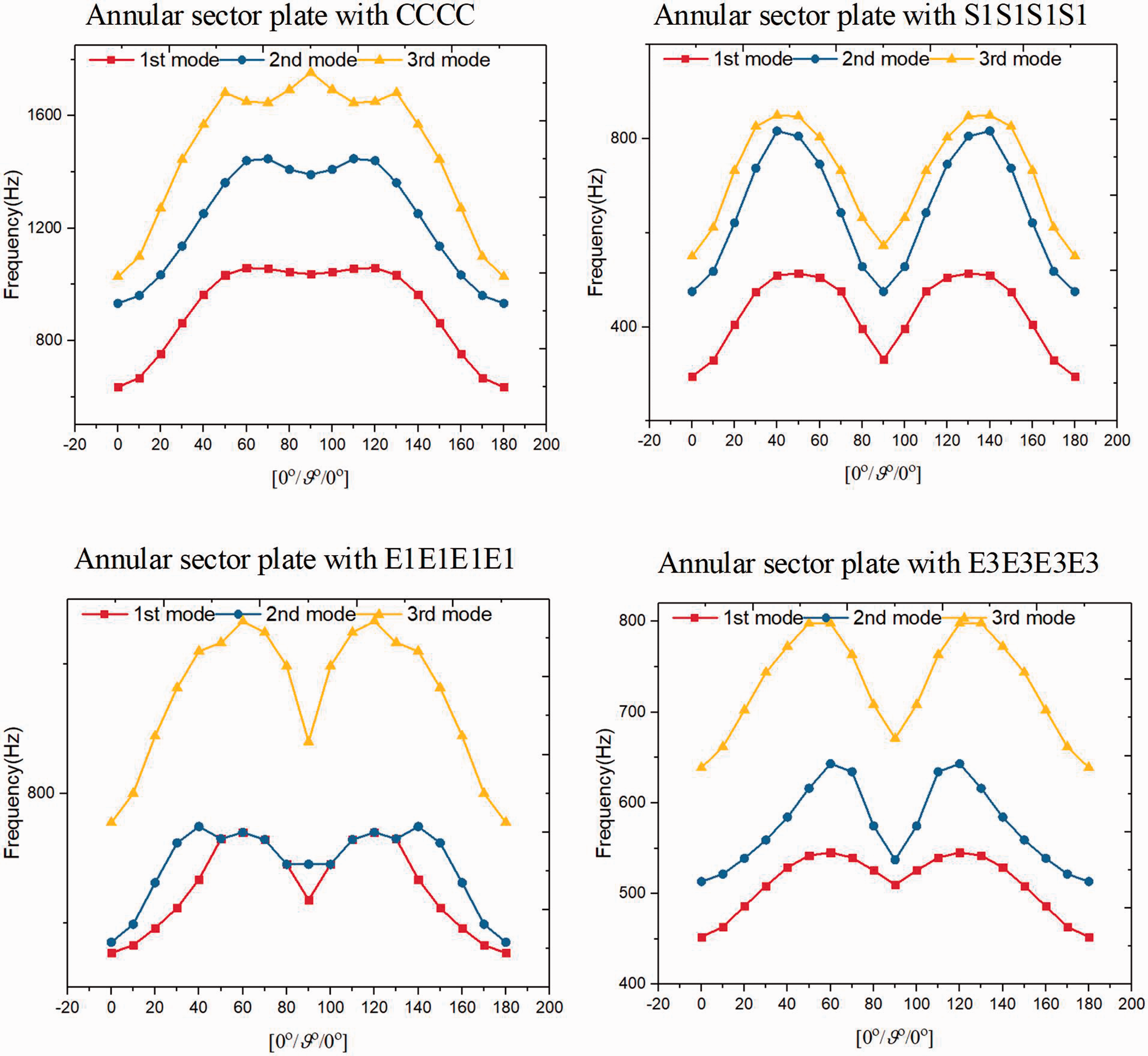
Variations of frequencies of annular sector plates under different boundary condition with respect to various fiber angle
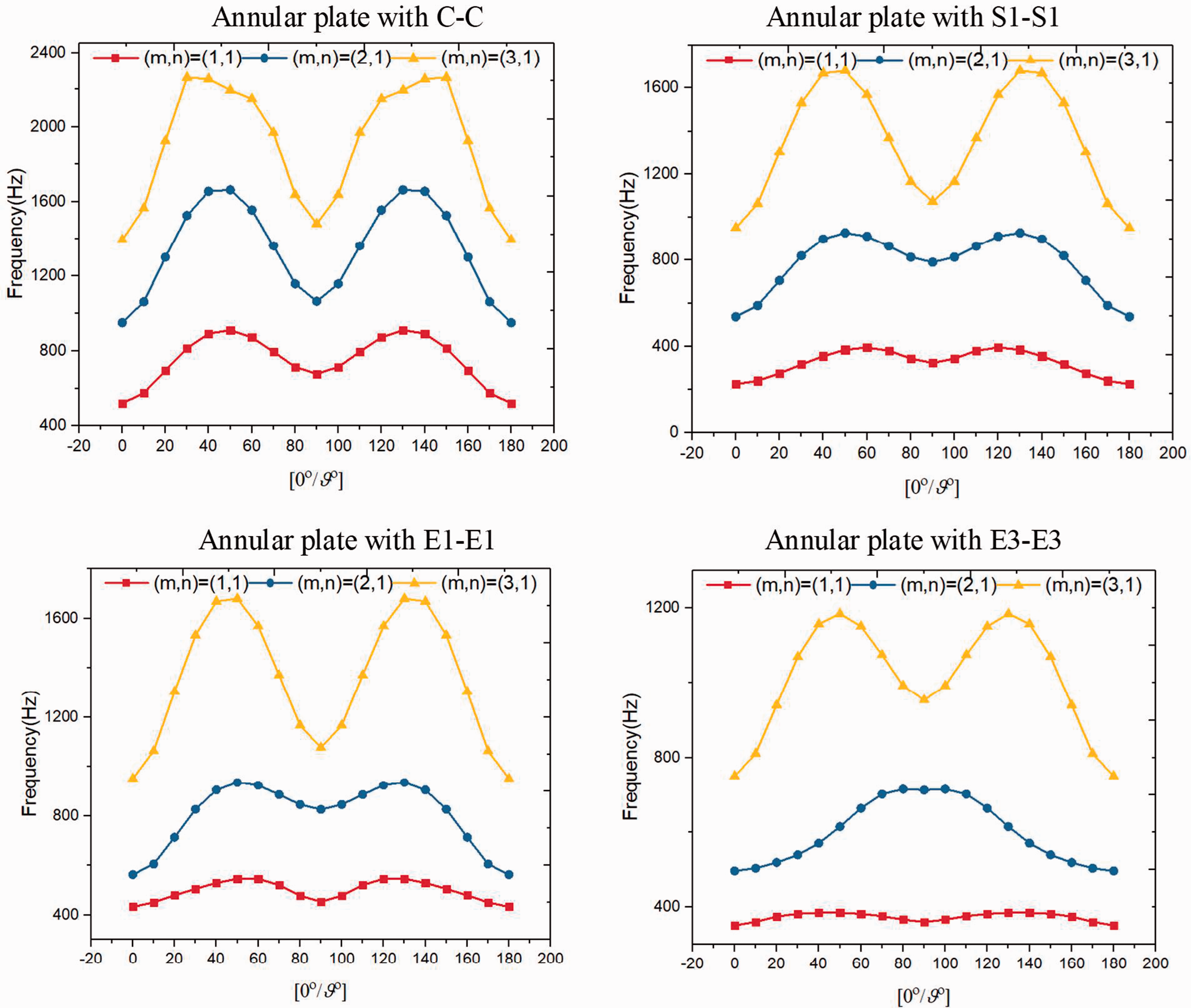
Variations of frequencies of annular sector plates under different boundary conditions with respect to various fiber angle
Conclusions
A semi-analytical method is developed for the in-plane vibration analysis of the composite laminated annular and sector plate with general boundary conditions. Based on the variational principle and multi-segment partitioning method, the theoretical model of composite laminated annular and sector plate is established. Boundary condition and continuous condition between segments are guaranteed by introducing penalty parameters. Compared with the existing methods, when the boundary conditions are changed, there is no need to modify the equations of motion, just modify the boundary penalty parameters, which is simple, convenient and practical. The comparison between the present solutions and numerical results show good convergence and accuracy of the present method. On this basis, some core research on in-plane vibration behavior is carried out, which can be used as benchmark data to provide comparison for future researchers.
Footnotes
Declaration of conflicting interests
The author(s) declared no potential conflicts of interest with respect to the research, authorship, and/or publication of this article.
Funding
The author(s) disclosed receipt of the following financial support for the research, authorship, and/or publication of this article: The authors gratefully acknowledge the financial support from the National Natural Science Foundation of China (Grant Nos. 51705537).