
Abstract
A novel composite wing with Z-pin reinforced foam core sandwich panels was presented. It has high torsional and bending stiffness as well as improved damage tolerance. The collapse modes of Z-pinned core were summarized and developed, and then the failure envelopes under various stress conditions were given based on the Tsai–Wu failure criterion. An analytical approach was developed to assess the bending-twist properties of wing box, and the change of ply orientation of sandwich panel facesheets on the coupling coefficient was demonstrated. The Z-pinning parameter is determined by the applied bending moment and transverse loads. Numerical examples were presented to show the design parameters of Z-pinning for a given load case.
INTRODUCTION
Composites offer advantages over conventional structural materials such as aluminum, steel, and other types of metal. These advantages include high strength and stiffness, low weight, and integral manufacture of large-scale component. More important, the properties of composite structure can be tailored to meet the requirements of a specific design by changing the arrangements of the fibers. The composites aircraft design is an advanced integrative technology for high structural efficiency, aeroelastic tailoring, and excellent stealthy performance (e.g., infrared camouflage). Study and practice show the percentage of load-carrying structure in airplane is more than 70%, so composites should be used as wing materials for an effective weight reduction.
High aspect ratio composite materials wing is generally used on long-duration aircraft, such as UAV (Unmanned Aerial Vehicle). The aspect ratio may exceed 10. This induces high bending moment in the wing box, and buckling of upper wing panel may occur. In addition, the torsional deformation will be excessively large if the torsional stiffness of wing box can not satisfy the requirement; flutter or aileron reversal are prone to happen in this situation.
Sandwich materials are widely used in the critical aerospace, marine, or construction applications for their desirable advantage of high flexural stiffness per weight ratio. Sandwich structures have high bending stiffness due to the separation of stiff composite facesheets by a relatively lightweight and thick core. The wing with sandwich panels has high torsional stiffness compared with a wing with beams at a same structure weight [1]. In addition, it exhibits higher buckling resistance and natural vibration frequency compared with a similar part constructed by monocoque design. Sandwich panels can carry high local aerodynamic force, and prevent wrinkling or buckling of skins under compressive load. More important, the use of composite tailoring of sandwich facesheets can meet the ratio requirement of the torsional stiffness to bending stiffness, wash-in will be reduced, and divergence speed of wing will be enhanced.
Composite sandwich structures suffer from problems such as debonding may occur either in the interface of facesheets and core or between the composite plies when it’s under out-of-plane impact loading, such as tool drop, bullet fragments, and hail impact. These failures will reduce the compression strength and critical buckling load significantly. It is difficult to reach the requirements of damage tolerance design especially for the upper wing panels. A good combination between skin and core material is very important in design consideration of sandwich structures.
The sandwich core should possess low density for the purpose of weight-efficiency when the thickness of panel is increased. Honeycomb or foam core are used in almost all sandwich materials. The polymer foam core is cheaper than honeycomb core, and it’s usually used as energy absorbers and thermal insulating materials. At the same time, foam core can increase surface area and allow stress to dissipate over a larger area than that offered by honeycomb core, which avoids affecting aerodynamic performance by the hollowness.
A novel foam core sandwich structure called Z-pin reinforced foam core sandwich has been developed [2,3]. It was proved that Z-pin reinforcement is effective in improving the mechanical properties of sandwich and enhancing the interfaces between facesheets and core, which improves sandwich damage resistance and tolerance [4,5]. The fabrication process of Z-pinned foam core sandwich is described in Figure 1.
Schematic of Z-pin reinforced foam core sandwich: (a) polymer foam, (b) pin insertion, (c) the core perform is laminated.
Based on the superiorities of Z-pinned foam core sandwich, an innovative mixed structure combined the advantages of wing with longerons and sandwich structures is proposed as illustrated in Figure 2. The wing panels are Z-pin reinforced foam core sandwiches and the longeron is weak compared with that of conventional double-longeron wing. Hereinto, the bending-induced axial load is mostly carried by the longeron flanges and sandwich panels, and the closed-section composed of sandwich panels and longeron webs sustains torque.
A sketch map of the novel wing box.
In the present study, the collapse modes and failure maps of Z-pin reinforced foam core are developed, and then the bending-twist properties of wing box are explored theoretically. The numerical examples are presented to show the design parameters of Z-pinning for a given load case.
THE MECHANICAL PROPERTIES OF Z-PIN REINFORCED FOAM CORE
In this part, the collapse modes of Z-pinned foam core are summarized and developed, and then the failure envelopes under various stress conditions are given based on the Tsai–Wu failure criterion.
The Out-of-Plane Compressive Strength of Z-Pinned Foam Core
The compressive strength of Z-pinned foam core is governed by the elastic buckling of pins, with the foam behaving as an elastic Winkler foundation in supporting the pins [6]. Neglecting the strain disturbance in foam due to the insert of pin, the through-thickness compressive strength of Z-pin reinforced foam core sandwich can be calculated by:
where μ denotes the constraint correction coefficient which reflects the constraint state of Z-pin ends suffered; β is the foundation modulus and represents the reaction force of foam per unit length of pin if the transverse deflection equals unity; Ep and dp are the elastic modulus and diameter of pin respectively; ω is the inclination angle of pin to the face normal; hco is the thickness of sandwich core; Ef is the elastic modulus of foam.
The number of half sine waves the pin buckles m is determined by:
The Out-of-Plane Tensile Strength of Z-Pinned Foam Core
The ability of pin to resist pull-out from facesheets determines the out-of-plane tensile strength of Z-pin reinforced foam core [7]. Based on equilibrium condition and deformation compatibility, we can obtain the out-of-plane tensile strength of Z-pinned foam core:
where ρ is the density of pinning; τj is the shear strength of the pin–facesheets interface; lpin denotes the length of the Z-pin penetrated into the facesheets.
The Shear Strength of Z-Pinned Foam Core
The shear failure modes of Z-pin reinforced foam core include foam shear failure, Z-pin pull-out, and Z-pin buckling under compression.
When micro-cracks initiate in the foam, the shear stress of reinforced core can be calculated consequently by using iso-strain assumption:
where ρe is the effective density of pinning, Gf and τfc denote the shear modulus and strength of foam respectively; Gfe is the equivalent modulus of pin inclusions reinforced foam matrix; which can be calculated by Mori-Tanaka method [8].
Foam shear failure is not the final failure mode, but it can induce the slight stiffness degradation of core.
Furthermore, the strength corresponding to Z-pin pull-out from facesheets can be expressed as follows [9]:
Now, consider the failure mode corresponding to Z-pin buckling under compression, it is described in Figure 3.
The sketch map of Z-pin buckling under compression.
Suppose the maximal shear load the unit cell can carry is Qmax. Based upon the equilibrium condition, we have:
where τf is the stress foam carried; Vp is the volume fraction of pin; σbuc is the buckling strength of Z-pin.
Further:
where lp is the length of pin. Based on the condition of deformation compatibility, the shear deformation of unit cell when pin-2 buckling can be educed: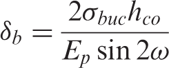
Then we have: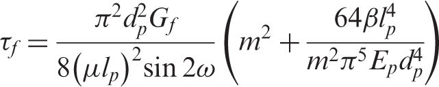
Finally, the shear strength corresponding to Z-pin buckling under compression can be obtained by combining Equations (6)–(9):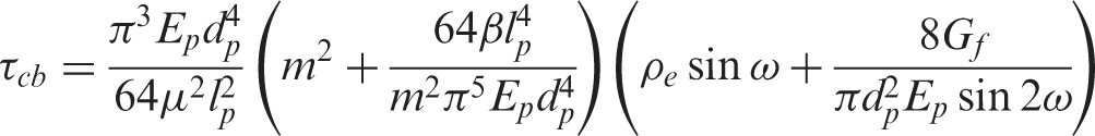
The Failure Envelope of Z-Pin Reinforced Foam Core
For anisotropic materials, the Tsai–Wu failure criterion can be written as the following form:
where σi and σj are on-axis stresses under material coordinates; Fi and Fij are two-order and four-order strength tensors depending on the tensile, compressive, and shear strengths of core.
Out-of-plane shear and compressive stresses are the primary stresses in sandwich core and the failure criterion (Equation (11)) becomes: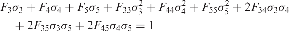
where σ3 = σz, σ4 = τzy, σ5 = τzx. The co-ordinate system is defined in Figure 1.
Because of symmetry, the failure stress is the same for positive shear and negative shear. Equation (12) satisfies this condition only if
Now consider only the stress components of uniaxial tension σt and compression σc in the z direction (Figure 1), and then σ4 = σ5 = 0. With these stresses, the failure criterion (Equation (12)) gives: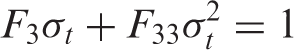
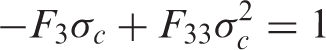
Combination of Equations.(14) and (15) yields: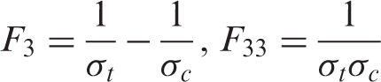
The strength parameters F44 and F55 are obtained in a similar way and given as follows: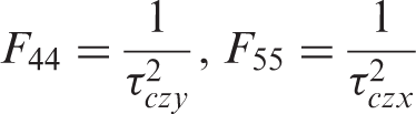
If σt, σc, τczy, and τczx are corresponding strength components, finally the failure criterion (Equation (12)) can be rewritten as:
Figure 4 demonstrates the failure surface of T300 carbon fiber pin reinforced Rohacell® 71 polymer foam core (Ef = 105 MPa, Gf = 42 MPa, τf = 1.3 MPa) in stress space (σz, τzx, τzy). The Z-pinning density is 12.5 pin/cm2, inclination angle of pin is 30°, Z-pin diameter is 0.5 mm, Young’s modulus of pin is 115 GPa, and core thickness is 10 mm.
The failure surface of Z-pin reinforced foam core in stress space (σz, τzx, τzy).
Furthermore, if only out-of-plane stresses σz and τzx are applied, which may be the primary stress status of sandwich beam core, Equation (18) can be simplified as:
The failure envelopes with different Z-pin diameters and inclination angles are plotted in Figure 5. The failure envelope is changed with the Z-pinning parameters. No failure occurs when the resultant stress is inside the failure envelope, and the core is in the elastic deformation stage. The core compression/tension-shear failure occurs on or out of the failure envelope. Because the tension failure mechanism is different from that of compression for Z-pin reinforced foam core, the failure envelope is an elliptical curve. At the same time, because the out-of-plane compressive stress can restrain Z-pin pull-out from facesheets, the center of the elliptical curve is not at the origin of coordinates.
The failure envelopes of Z-pin reinforced foam core in stress space (σz, τzx).
THE BENDING-TWIST PROPERTIES OF WING BOX
The upper and bottom wing panels are composite sandwich structures. Facesheets are thin compared with the sandwich core, and the core’s in-plane stiffness is small compared with the in-plane stiffness of facesheets. The expression for the in-plane loads 
where
It’s considered that the thickness of the sandwich core remains constant and the in-plane stiffness of the core is negligible. Under these assumptions the 
where di (i = 1,2) denotes the distance between the facesheets and reference plane of sandwich; the subscripts ‘1’ and ‘2’ denote the top and bottom facesheets; the extensional, coupling, and bending stiffness matrices of facesheets can be obtained as: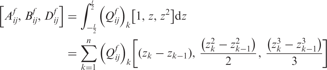
where Qijf are the components of the transformed lamina stiffness matrix and n is the number of laminas in the composite facesheets; zk denotes the distance between kth layer and the medium plane of the skin.
When the top and bottom facesheets are identical and their layup is symmetrical, then 
By neglecting Ny, Equation (23) can be rewritten as: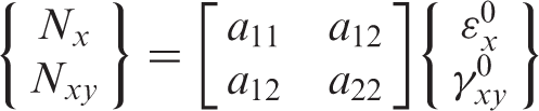
where: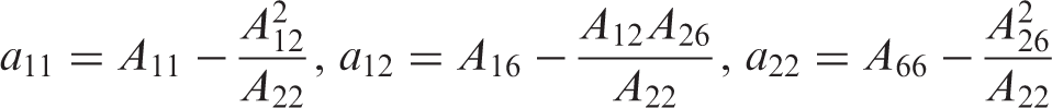
Aij is the in-plane stiffness of sandwich panels, given by Equation (21).
For a wing box subjected to torque Mxy, based upon the equilibrium condition, we have: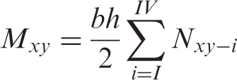
where b and h are illustrated in Figure 6.
The sketch map of wing box.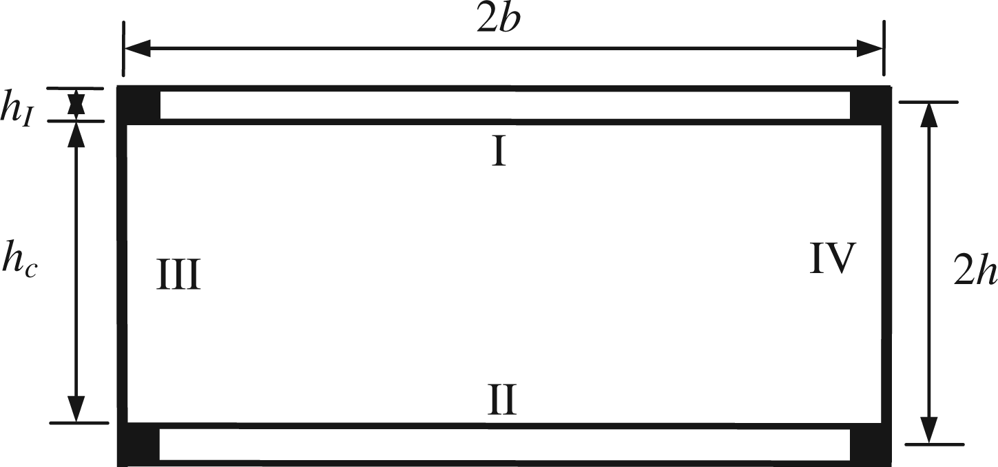
Substitution of Equation (24) into Equation (26) gives: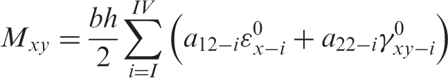
Based on the condition of deformation compatibility, we obtain: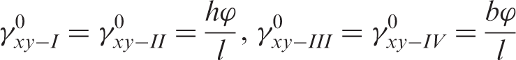
where φ is the torsion angle; l is the length of wing box.
The longeron web sustains shear force mainly, and extension-shear coupling should be avoided, so balanced laminates is used generally. Thereupon, A16 −
III
= A26 −
III
= A16 −
IV
= A26 −
IV
= 0. By using εx = hκx and substituting Equation (28) into Equation (27):
where φ‾ = φ/l.
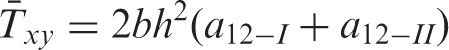
Consequently, the torsional stiffness of wing box is comprised with pure torsional stiffness Txy and twist-bending coupling stiffness 
For a wing box subjected to bending moment Mx, the equilibrium equation is:
where Myt, Mfb, and Mbb are the bending moments carried by longeron flanges, webs, and wing panels. The contribution of the Z-pinned core to the in-plane force is neglected.
The bending moment carried by longeron flanges is:
where Ex − IS−I and Ex − IIS−II are the equivalent tension stiffnesses of front and back longeron flanges respectively; κx is the curvature of reference plane of wig box.
The bending stiffnesses of longeron webs are:
By combining Equations (24) and (32)–(34), the condition of deformation compatibility described before, it yields:
Consequently, the bending stiffness of wing box is comprised with pure bending stiffness Wx and bending-twist coupling stiffness 
Changing the orientations of special one or all, plies are general methods for obtaining an appropriate stiffness of composite structures. In order to demonstrate how the ply arrangements influence the bending-twist properties of wing box, the numerical results are presented in Figure 7.
The coupling properties of wing box vs ply orientation of sandwich panel facesheets: (a) orientation change of 0° layer, (b) orientation change of 90° layer, (c) orientation change of ±45° layer, (d) orientation change of all layers.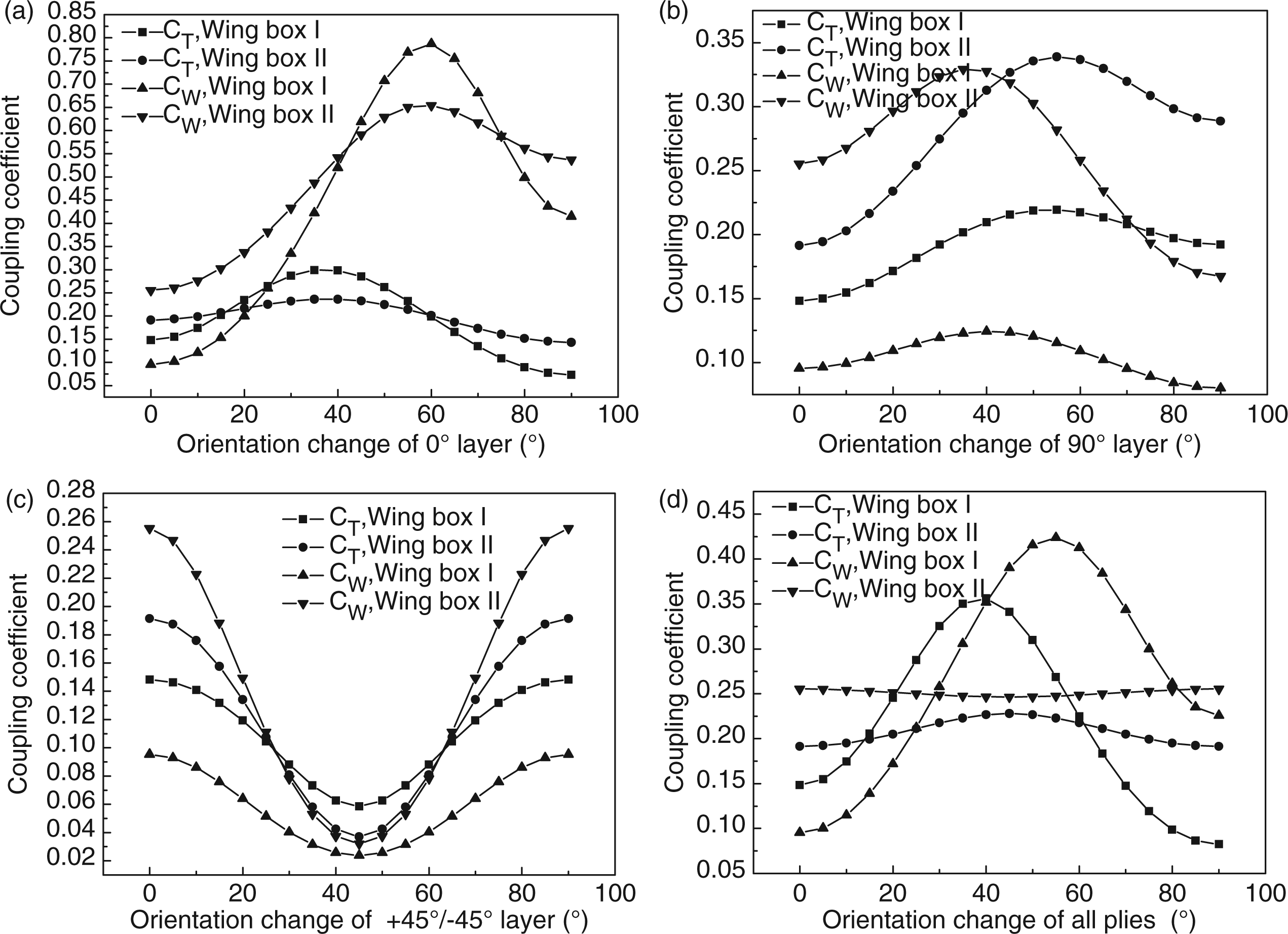
The twist-bending and bending-twist coupling coefficients are defined as CW = W‾/W and CT = T‾/T. Considering two kinds of composite wing box, the first lays the ply stacking and proportion of laminates based on the load condition. The upper and bottom sandwich panel facesheets are combined with a lay-up configuration of [−45/02/45/02/90/0]S and [45/02/−45/02/90]S, respectively. The lay-up of front and back longeron flanges is [45/03/90/0/−45/02]S and longeron webs is [−45/0/45/90/±45]S. All of the lay-up of the second wing box panels is [45/0/−45/90/45/0/−45/90]S and the others are same as the first. The elastic properties of single layer used for the calculations are E_L = 135 GPa, E_T = 8.8 GPa, G_LT = 4.5 GPa, and v_TL = 0.33. The dimensions of wing box section are 300 mm × 150 mm.
Figure 7 shows the bending-twist properties of wing box change with the ply arrangements significantly. Changing the orientation of dominant plies can effectively optimize the stiffness of composite wing. In all the given work, the two coupling coefficients have extremums.
THE DESIGN OF Z-PINNED FOAM CORE FOR WING SANDWICH PANEL
As mentioned previously, the shear stress τzx is the primary stress in sandwich panel core (Figure 2 – here x axis is located along the spanwise direction), and Z-pin reinforcement can enhance the shear properties of foam significantly. For using Z-pin reinforced foam core, a reasonable spanwise Z-pinning parameter should be designed to make the lowest weight of wing. This section will take the upper sandwich wing panel for example, and the subscript denotes the upper panel is leaved out. The analysis of bottom panel is completely similar to that of the upper panel.
The moments acting on the panels when the curvature of wing box is κx: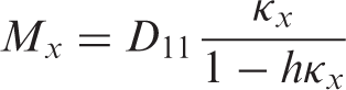
where h is illustrated in Figure 6; D11 is element 1–1 of the bending stiffness matrix of upper panel, which can be obtained from [10].
The thickness of facesheets is small compared with the height of wing box, and it is assumed as membrane reasonably. The facesheets of upper wing panels sustain in-plane compression forces, shown as Figure 8. The bending moment carried by the upper panel can be expressed as: The sketch of the considered problem of wing box.
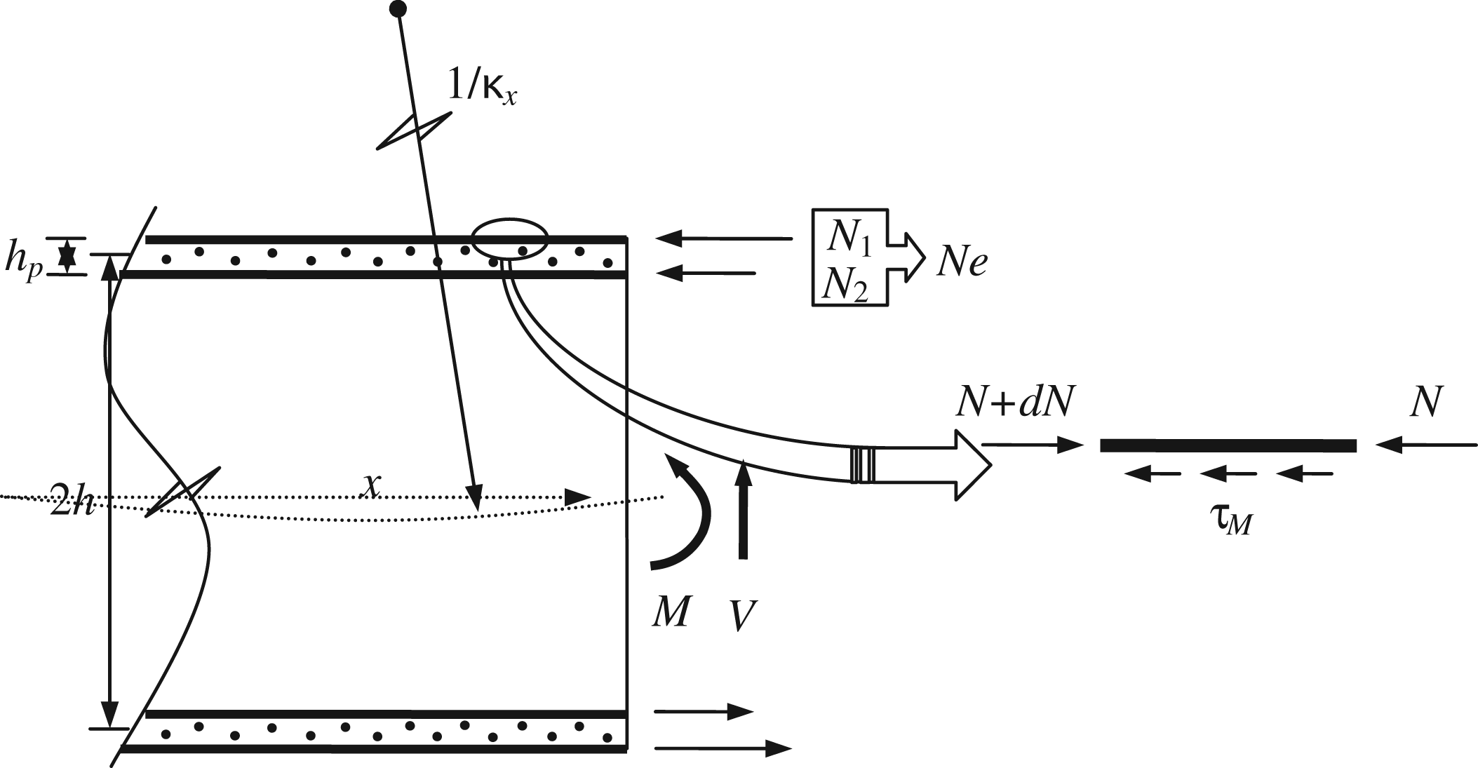
where hp denotes the distance between the midplanes of the sandwich facesheets. Equilibrium of the facesheets requires: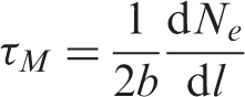
where τM = Gcγc is the shear stress in core induced by moments.
Based on the condition of deformation compatibility and combined Equations (39) and (40), it yields: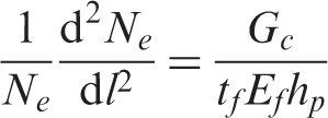
where tf is the thickness; Ef is the equivalent elastic modulus of facesheets. This equation should satisfy the conditions: Ne(0) = 0 and N′e(L/2) = 0.
The shear modulus of the Z-pinned foam core is given by [8]:
At the same time, the rigidity distribution method is used to calculate the shear force in panel core induced by the applied transverse load V:
where Wx-
i
is determined by Equation (34):
where tfi is the thickness; νfi is the Poisson’s ratio of facesheets; δ11- i is element 1–1 of the facesheets bending compliance matrix; hi denotes the distance between neutral planes of the sandwich skins.
Then the total shear stress in sandwich panel core is:
Consider a straight wing box with high aspect ratio subjected to a uniformly distributed load 10 N/mm2. Figure 9 shows the variants of design Z-pinning parameters along the spanwise direction. In the present study, the design of Z-pinned core will account for the shear failure modes described previously. The properties and dimensions of two types of wing boxes are the same as before. The properties of Rohacell® foam 31: Ef = 36 MPa, Gf = 13 MPa, τf = 0.4 MPa; Rohacell® foam 51: Ef = 70 MPa, Gf = 19 MPa, τf = 0.8 MPa. The Young’s modulus of pin is 115 GPa.
The variants of design Z-pinning parameters: (a) the variants of pinning density, (b) the variants of pin diameter (Wing box II).
Figure 9(a) shows that the range from wing tip to 107.4 mm length need not reinforce for wing box I, and this length is 160.1 mm for wing box II. The density of pinning increases in a monotonic manner with respect to the increase of spanwise distance from wing tip when the diameter of pin is fixed at 0.5 mm. When big inclination angel is used, the density of pinning can be decreased. Figure 9(b) shows the range which need not reinforce increases when higher density foam is employed. Here the inclination angle of pin is 20°. The pin diameter increases with respect to the increase of spanwise distance. The increasing trends change at about 500 mm and 600 mm length because the controlled failure modes transfer from Z-pin buckling to pull-out.
CONCLUSIONS
A novel composite wing with foam core sandwich panels was presented in this article. The wing panel was reinforced by Z-pins for enhancing its damage resistance and tolerance. The collapse of Z-pinned foam core was summarized and developed. The failure envelope of reinforced core is ellipsoid surface (elliptical curve), and its center is not at the origin of 3D (2D) stress-space coordinates. The theoretical analysis of bending-twist coupling properties was presented and numerical results were given for two kinds of composite wing boxes. The bending-twist coupling properties change with the ply orientation and this shows that wing box can be tailored to meet the requirements of aerodynamics. The sandwich panel core sustains shear force and Z-pinning parameters can be designed based on the load case.