
Abstract
The development of composite coatings essential to improve the wear and corrosion resistances of the materials employed in numerous applications, such as automobile, chemical, medicine, construction, aerospace, and biomedical industries. In this study, we presented a double-layer coating technique, which consisted of a thermal-sprayed titanium (Ti) layer and a micro-arc oxidation (MAO) film on AISI 1020 steel. The effect of the composite coatings (Ti/MAO) on wear and corrosion resistance was investigated. To obtain a coating thickness from 250 µm to 450 µm, the prepared specimens were coated with Ti (99.9% pure) by arc spraying. Then, the Ti/MAO films were deposited on Ti coatings. The current density of MAO was fixed at 35 A/dm2, the voltages were 250, 300, 350, 400, and 450 V, and the duration of the MAO process was 10 min, Measurements of film thickness, microstructure, microhardness, X-ray diffractometry analysis, and scanning electron microscopic observation were performed for determining the characteristics of the composite coatings (Ti/MAO). Potentiodynamic polarization curves were used to compare the corrosion resistance of these composite coatings. A ball-on-disc wear test, using an oscillation friction wear tester, was carried out at room temperature according to the ASTM G99 standard to determine the wear resistance. Among all the specimens, Ti/MAO (400 V) had the greatest hardness, lowest friction coefficient, least weight loss, and longest sliding distance. The sliding distance of Ti/MAO (400 V) was about 1.7 times higher than those of Ti. The open-circuit potential of Ti/MAO (400 V) was about 1.7 times better than those of Ti. The corrosion currents of Ti/MAO (250 V) and Ti/MAO (400 V) were decreased by MAO about 95% and 92%, respectively. Although the corrosion current of Ti/MAO (400 V) was higher than that of Ti/MAO (250 V), Ti/MAO (400 V) had better effects in other tests. According to the results, Ti/MAO (400 V) presented the best performance among all the specimens and provided improved protection to both Ti and substrate.
Introduction
Currently, titanium (Ti) and its alloys are one of the most attractive materials used in the automobile, chemical, medicine, construction, aerospace, and biomedical industries due to their high strength to weight ratio, low density, excellent corrosion resistance, and high biological compatibility with the human body. 1 However, the low wear resistance and high friction coefficient of Ti and its alloys limit their extensive applications. A series of engineering techniques, such as physical vapor deposition, chemical vapor deposition, thermal spraying, and microarc oxidation (MAO), are used to improve the tribological performance. 2 –4
Thermal spraying is a well-developed coating technique. First, the materials are melted and softened by applying either chemical or electrical energy to particles. Subsequently, the melted particles are sprayed onto a substrate by compressed air or argon. Over the past decade, thermal-sprayed coatings have been widely used in the electronic, chemical, and aerospace industries because of their high deposition rate and low cost. Moreover, this technique can be used with a variety of materials. Thermal-sprayed Ti coatings have several applications, namely, anode and cathode protection of reinforced concrete bridges, erosion-resistant coatings for molten aluminum, biocompatible coatings for human implants, and corrosion-resisting agent in chloride solutions. 5 –8
Composite coatings are generally classified into four types: a metal matrix composite, ceramic matrix composite, polymer matrix composite, and an intermetallic composite. These composite coatings are usually sprayed from an already prepared powder by blending, spray drying agglomeration, mechanical alloying, self-propagating high-temperature synthesis, electroplating, among others. Some of the composite coatings are prepared by posttreatment methods, such as sealing, plating, anodizing, nitriding, carburizing, and sulfurizing. 9,10
MAO, also called plasma electrolytic oxidation, is a novel, simple and environmental-friendly technique capable of depositing oxide ceramic layers on the surface of valve metals, such as Ti, Mg, Al, Zr, and their alloys. 11 –13 The immersion of a metal into an electrolytic solution resulted in the formation of a thick oxidation layer on the metal surface. The oxidation layer was electrically insulated to a great extent and exhibited excellent resistance to wear and corrosion. 14 –16 In comparison with conventional anodizing processes, the MAO process could be carried out at higher voltages and current density, hence resulting in a higher deposition rate than that of traditional anodized layers. 17 MAO is a complicated process as it combined the properties of diffusion, electrophoresis, thermal chemistry, and phase transformation. In this process, the local instantaneous temperature inside the microarc discharge channels can lead to the melting of the metal. 18,19 The molten metal ejected from the discharge channels is cooled by the electrolyte solution, forming a ceramic layer on the metal surface. 20,21 The effects of the MAO process parameters, including current mode, spark voltage, current density, impulse frequency, duty ratio, and pulse duration time on the plasma characteristics, surface morphology, microstructure, and corrosion resistance of oxides grown on Ti alloy, were abundantly studied. 22 –26
However, the high cost of Ti and its alloys is another restriction for their use in those applications compared to aluminum and steel alloys. To reduce the production costs and to preserve the good performances of Ti and its alloys, duplex coatings were presented in recent years. 27 –34 Although steel can be used as the substrate to reduce the production costs, the MAO process cannot be applied to steel directly, because the ferric oxide escapes from the substrate during oxidation process. Chang et al. 35 presented a solution for this problem by first applying a coating of aluminum on the steel substrate using a thermal spraying technology. Durdu et al. 36 used electro-spark deposition and MAO processes to improve the mechanical properties and the tribological performance of steel.
In this study, we developed a double-layer coating comprising a thermal-sprayed Ti layer and MAO oxide film for application on AISI 1020 carbon steel substrates to retain the advantages of Ti, whilst strengthening the wear and corrosion resistance of both Ti and the substrate and reducing the production costs. The MAO voltage operated at 250, 300, 350, 400, and 450 V and the current density was 35 A/dm2. The duration of the MAO process was 10 min. The coating characteristics, wear performance, and corrosion performance of the double-layer coatings were evaluated using scanning electron microscope (SEM), X-ray diffractometry (XRD), microhardness testing, electrochemical polarization, and ball-on-disc tribometry, and the effects of the anodizing parameters on the wear and corrosion performances were discussed.
Experimental method
Experimental apparatus and procedure
A commercially AISI 1020 low carbon steel with 3-mm thick was cut into several smaller plates of 50 × 50 mm2; the cutout plates were used as specimens in this experiment. All the specimens were grit-blasted to grade SA3 in compliance with the Swedish standard SIS 05 59 00. Subsequently, the specimens were cleaned with ethanol and distilled water. To obtain a coating thickness between 250 µm and 450 µm, the prepared specimens were coated with Ti (99.9% pure) by arc spraying with an arc current of 200 A, an arc voltage of 28 V, and an atomizing pressure of 60 psi. Prior to carrying out the MAO process, the Ti-coated specimens were polished to obtain an average surface roughness (Ra) of less than 1.6 µm. Then, the specimens were masked with 3M aluminum foil tapes and plastic epoxy on the edges for water resistance. To prevent the chemical reaction of steel in the MAO process, the specimens were immersed in the sealing agent for 10 min, avoiding the penetration of electrolyte through the pores of Ti coatings into steel. The power would centralize on the steel if the electrolyte contacted steel in the MAO process. Consequently, no arc spark was observed on the surface of the Ti coatings. The ferrous hydroxide produced on the steel would cause the peeling of the Ti coatings. The prepared specimens were subsequently connected to the anode and immersed in an alkaline electrolyte composed of NaOH (5 wt%) and Na2SiO3 (0.5 wt%). The temperature of the electrolyte was adjusted to 20°C using a cooler system. The DC power supply was operated at 250, 300, 350, 400, and 450 V and the current density was 35 A/dm2. The duration of the anodizing process was 10 min. The treated specimens were denoted as Ti/MAO (V), respectively. The duty cycle and frequency were designated to be 50% and 1000 Hz, respectively.
Analysis of coatings characteristics
Measurements of film thickness, microstructure, microhardness, and XRD analysis were carried out to determine the characteristics of the double-layer coatings. The thickness of the Ti/MAO coatings was measured using a thickness measurement gauge (Defelsko Positector 6000, Proctor Avenue Ogdensburg, NY, USA) at five randomly selected locations. The surface and cross-section morphologies of the specimens were investigated by SEM (Nova Nano-SEM 450; FEI Company, Oregon, Ohio, United States). The Vickers hardness (Hv) of the TiO2 coatings was measured using a microhardness tester (Shimadzu HMV-2, Nishinokyo Kuwabara-cho, Nakagyo-ku, Kyoto, Japan) under an indentation load of 100 g and 15 s of testing time. XRD analysis (Bruker D8 ADVANCE, Belmont Business Park, Bede House, Durham DH1 1TW, United Kingdom) was used to examine the phase composition of the coatings by scanning in the range of 2θ = 10–90° and 0.02° step size.
Corrosion test
A potentiostat (VersaSTAT 4; Ametek Scientific Instruments, Cassatt Road Berwyn, PA, United States) was used to plot the potentiodynamic polarization curves. The measurements were performed in a three-electrode cell: platinum was used as the counter electrode, a saturated calomel electrode was used as the reference electrode, and a specimen was used as the work electrode. The test area of the specimens was 1 cm2. Prior to the test, the specimens were immersed for 10 min in sodium chloride (NaCl, 3.5 wt%) solution prepared with deionized water (18 MΩ cm) obtained from a Millipore (Burlington, Massachusetts, United States) Milli-Q SP water purification system to balance the potential of the specimens. The polarization scan rate was 1 mV/s.
Ball-on-disc wear test
A tribometer (Anton Paar, Timber Ridge Dr. Ashland, VA, United States TRB3: pin-on-disk tribometer) was used to perform a ball-on-disc wear test. Tungsten carbide balls with a diameter of 6.35 mm and hardness in the range of 1500–2000 Hv were in the test at room temperature according to the ASTM G99 standard. Constant loads of 2 N were applied to the specimen. The sliding track diameter, velocity, and distance of the test ball were 6 mm, 8 m/min, and 200 m, respectively. The friction coefficients of the coatings were also recorded during the tests. The antiwear performance of the test specimen was defined by the coefficient of friction, weight loss, and the sliding distance. The sliding distance is defined as the distance the coatings wear through. The weight loss of the specimen was measured using an electronic analytical balance (Mettler AT261; Mettler) with a minimum reading of 0.01 mg. After the sliding tests, the worn surface morphologies of the coatings were investigated by SEM analysis.
Results and discussion
Coatings characteristics
By polarizing the metal to its dielectric breakdown voltage in a suitable electrolyte in the MAO process, these coatings formed at the sites of high-temperature microdischarges had advantages of both electrochemical and thermal oxidations simultaneously. 37 The high-voltage intensity will form a coarse coating surface and increase the discharge density. 38
During the MAO process of all specimens, the applied voltage and current were slowly increased. After about 120 s, the applied current was constant, and the voltage fluctuated slightly. The micrograph of the surface of Ti, Ti/MAO coatings, and the cross section of Ti/MAO is shown in Figure 1(a) to (c).
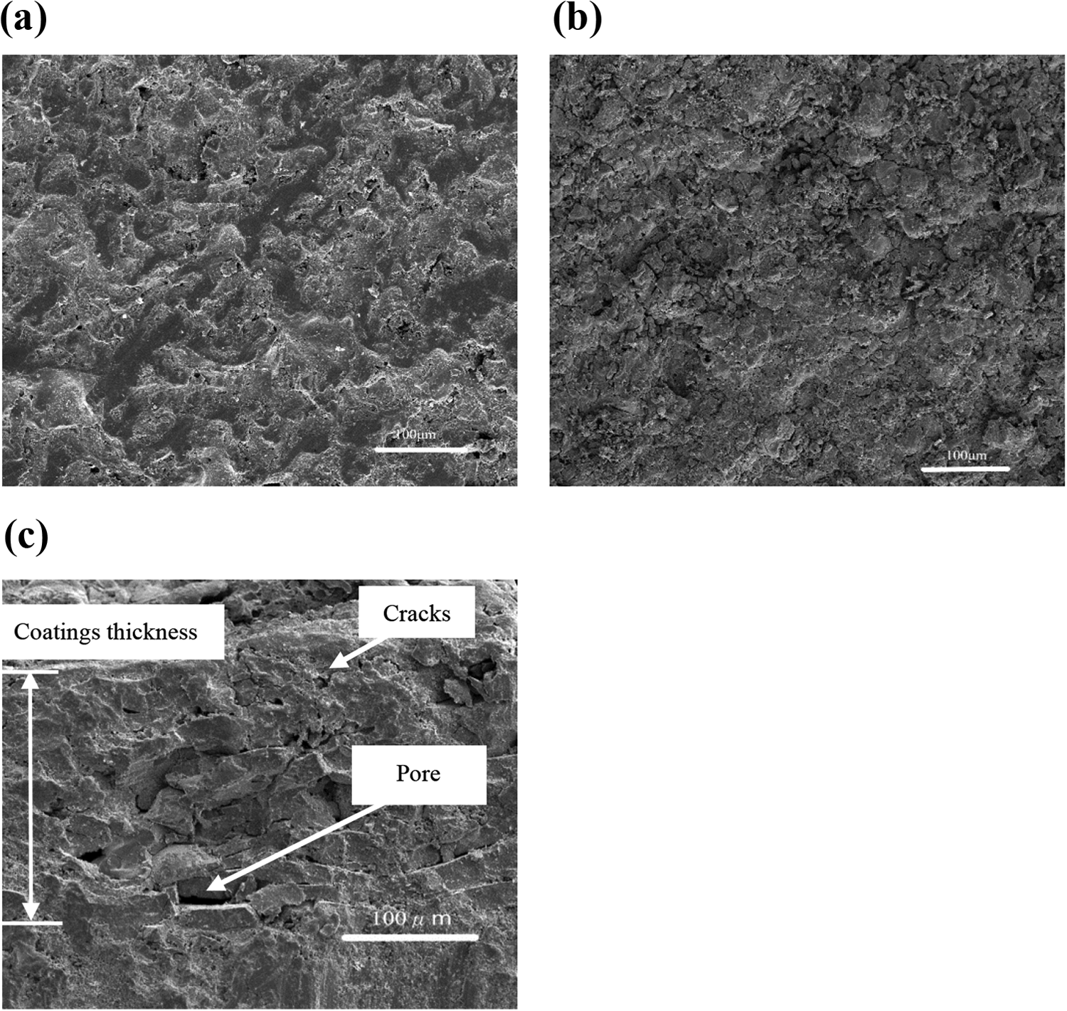
SEM observation of Ti and Ti/MAO coatings. (a) Ti surface ×500, (b) Ti/MAO (250 V) surface ×500, and (c) Ti/MAO cross section ×500. SEM: scanning electron microscope; Ti: titanium; MAO: microarc oxidation.
Figure 1(a) shows many irregular protrusions connecting each other and no apertures or microcracks could be observed on the Ti surface. Figure 1(b) shows several craters, hills, and microcracks on the Ti/MAO coating surface. Figure 1(c) shows no significant interface between the Ti and the coating layers but a few pores and microcracks can be observed. These pores and microcracks could have been interconnected and probably extended from the surface to the base of the material, thus decreasing corrosion and wear resistance. 39
In Figures 2(a) to (e) and 3(a) to (e), representing MAO voltages of 250, 300, 350, 400, and 450 V and a duration of 10 min, the craters, hills, and microcracks are observed on the surface of all Ti/MAO coatings. Figure 2(a) and (d) shows fewer craters and microcracks on the surface of Ti/MAO (250 V) and Ti/MAO (400 V). But the surface of Ti/MAO (400 V) is flatter than that of Ti/MAO (250 V). In Figure 2(b), (c), and (e), more craters, hills, and branches are visible on the surfaces of Ti/MAO (300 V), Ti/MAO (350 V), and Ti/MAO (450 V). Therefore, the surface of Ti/MAO (300 V), Ti/MAO (350 V), and Ti/MAO (450 V) is more complex than those of the other MAO coatings. Figure 3(a) to (e) shows that microcracks, craters, and hills gradually grew up as the MAO voltage increased. The craters of Ti/MAO (350 V) are bigger than the other Ti/MAO coatings. The branches can be observed on the surface of Ti/MAO (250 V), Ti/MAO (300 V), Ti/MAO (350 V), and Ti/MAO (450 V). The branches gradually grew up from Ti/MAO (250 V) to Ti/MAO (350 V) and became more and shorter at Ti/MAO (450 V). But the branches decreased at Ti/MAO (400 V). It implied that the surface of Ti/MAO (400 V) was denser than the other Ti/MAO coatings. The craters, branches, and microcracks on the surface are considered as adverse factors for coating properties. 39
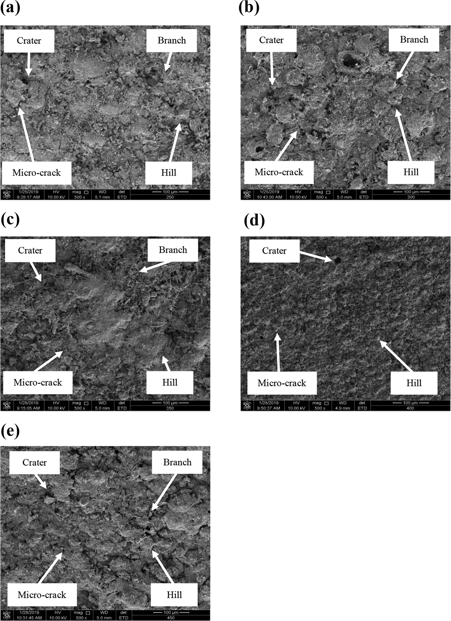
SEM micrographs of Ti/MAO coatings prepared at various voltages: (a) 250 V, ×500, (b) 300 V, ×500, (c) 350 V, ×500, (d) 400 V, ×500, and (e) 450 V, ×500. SEM: scanning electron microscope; Ti: titanium; MAO: microarc oxidation.

SEM micrographs of Ti/MAO coatings prepared at various voltages: (a) 250 V, ×5000, (b) 300 V, ×5000, (c) 350 V, ×5000, (d) 400 V, ×5000, and (e) 450 V, ×5000. SEM: scanning electron microscope; Ti: titanium; MAO: microarc oxidation.
The thickness of the Ti/MAO coatings is shown in Figure 4 and it can be observed that the thickness of the Ti/MAO coatings depended on the voltage of MAO. It implied that the higher voltage provided higher power and a coating growth rate in the MAO process.

The thickness measurement results of Ti/MAO coatings at each MAO voltage. Ti: titanium; MAO: microarc oxidation.
The compositions of Ti and Ti/MAO are illustrated in Table 1, revealing that elements from electrolytes were incorporated into the Ti/MAO coatings. For the samples with Ti/MAO, there were vestigial amounts of Fe from the substrate on the coating surfaces and this amount decreased when the MAO voltage increased. In addition, there was extra Ti, Si, and a smaller amount of Fe, C, O, and Na on the surface of Ti/MAO (400 V).
Wear test results of Ti/MAO coatings.

Ti: titanium; MAO: microarc oxidation.
The hardness measurements of the surface of Ti/MAO are shown in Figure 5. Five measurements were performed for Ti and all the Ti/MAO coatings, and the average hardness value was calculated. The hardness of Ti is 322 Hv; the hardness ranges of Ti/MAO are 232–338 Hv. There is no obvious trend to prove the hardness related to MAO voltage. According to the surface micrographs (Figures 2 and 3), the coating structure of Ti/MAO (250 V) and Ti/MAO (400 V) has less craters, branches, and microcracks. The coating structure of Ti/MAO (250 V) and Ti/MAO (400 V) is more compact than those of other Ti/MAO coatings. When the MAO voltage increases from 300 V to 400 V, the hardness of Ti/MAO coatings increases gradually, and Ti/MAO (400 V) has the highest hardness.

Microhardness measurement results of Ti and Ti/MAO coatings. Ti: titanium; MAO: microarc oxidation.
Table 1 presents the composition of Ti/MAO coatings, it could be observed that the hardness increased when the amount of Si and Ti increased. Ti/MAO (400 V) has extra Ti, Si, and a smaller amount Fe, C, O, and Na, and it has the highest hardness. Ti/MAO (450 V) has more craters, microcracks, and shorter branches on the surface, and it has the lowest Si and Ti, therefore, the hardness is the lowest. The results are similar to the previous research. 30
The XRD analysis results of Ti and the Ti/MAO coatings are shown in Figure 6. The diffraction profile indicated that the compositions of the Ti and Ti/MAO coatings are different. The XRD analysis results of Ti show the peaks of Ti and Ti3O. The XRD analysis results of Ti/MAO show the peaks of TiO2. The presence of TiO2 suggested that the vigorous oxidation reaction had occurred on the Ti surface during the MAO process. After MAO processing, the rutile TiO2 could be observed in the main composition of the coatings. The rutile TiO2 was formed at the temperature range of 550–1000°C. The rutile TiO2 has a symmetrical and stable crystal structure, better corrosion, and higher hardness. 40
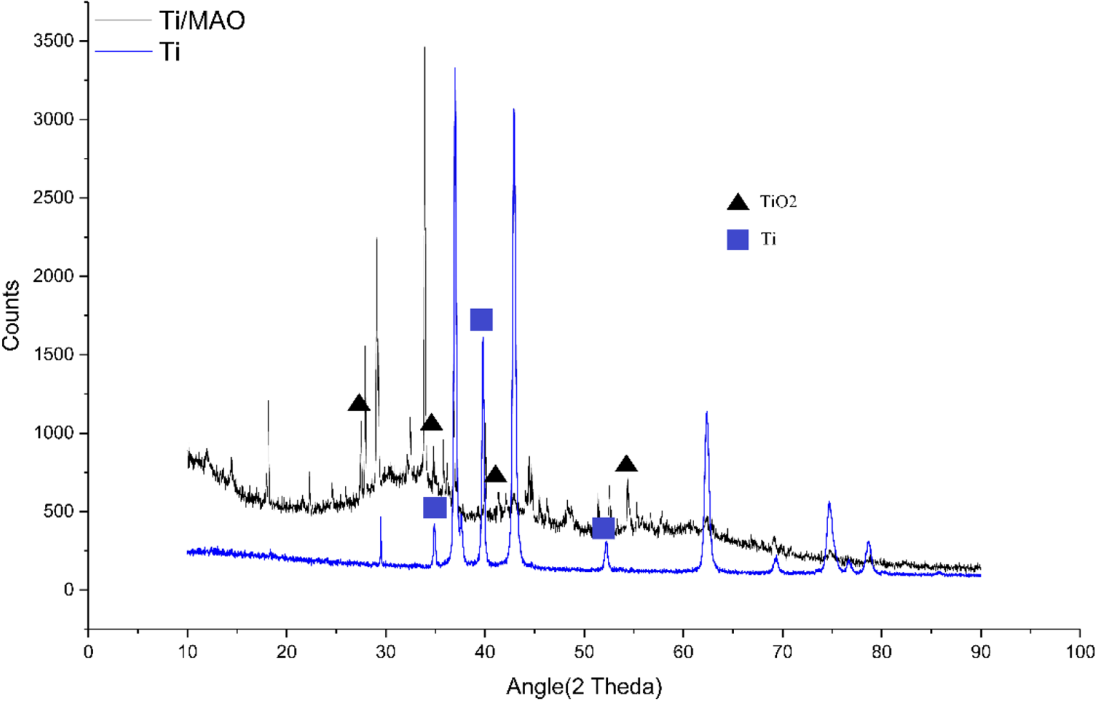
XRD analysis results of Ti and Ti/MAO coatings. XRD: X-ray diffraction; Ti: titanium; MAO: microarc oxidation.
Corrosion test
The potentiodynamic polarization curves of the Ti and Ti/MAO coatings are shown in Figure 7 and Table 2. The open-circuit potentials of the Ti, Ti/MAO (250 V), Ti/MAO (300 V), Ti/MAO (350 V), Ti/MAO (400 V), and Ti/MAO (450 V) coatings are approximately −0.78 V, −0.47 V, −0.52 V, −0.54 V, −0.44 V, and −0.54 V, respectively. The results imply that all Ti/MAO coatings have better corrosion resistance than Ti. Moreover, Ti/MAO (400 V) has the highest corrosion potential, and it was about 1.7 times better than those of Ti.

Potentiodynamic polarization test results.
Corrosion test results of all samples.

The corrosion current of Ti is 2.74 × 10⁻³ (A/cm2) higher than all the Ti/MAO coatings; thus, the corrosion velocity of Ti was highest. Ti/MAO (250 V) had the lowest corrosion current (1.46 × 10⁻⁴ A/cm2), so it had the lowest corrosion velocity. The corrosion currents of Ti/MAO (250 V) and Ti/MAO (400 V) were decreased by MAO about 95% and 92%, respectively.
Because of the more compact structure, the NaCl solution hardly penetrates through the pores of Ti/MAO penetration into the substrate. Therefore, Ti/MAO (400 V) has better corrosion resistance. As a result, the corrosion test proved that the MAO coatings provided better coverage than Ti because of the formation of a thicker layer on their surfaces.
Ball-on-disc test
The micrographs of Ti and Ti/MAO surface slid 300 cm by the tungsten carbide ball are shown in Figure 8(a) to (c). The results of the ball-on-disc test are presented in Table 3 and Figure 9. For comparison, Figure 8(a) and (b) is dissimilar but the abraded surface could be observed. In Figure 8(a), no significant removal can be observed. Some “fish scales” are present on the worn track of Ti, indicating that the abrasive wear occurs in the wear process. In the beginning, when the tungsten carbide ball wore against the MAO coatings, the presence of irregular protrusions, craters, hills, and microcracks on the surface caused an unstable friction coefficient (Figure 8(b) and (c)). Also, the irregular protrusions on the surface of Ti/MAO endure the normal stress and shear stress at the contact points with the tungsten carbide ball. After a while, the irregular protrusions of the coatings were crushed and the surface became flat. Therefore, the friction coefficient became stable gradually. The formation of the microcrack on the coating surface was caused by repeated sliding contact. 41 The microcracks on the worn surface can propagate freely and cause the subsequent delaminating because of the brittleness of Ti/MAO and the presence of wear reciprocating stresses. On the worn surface of the MAO coating, extensive abrasive wear and adhesive peel holes can be observed.

Surface optical microscope images of ball after wear test under load of 2 N and a traveling speed of 8 m/min. (a) Ti, ×500, (b) Ti/MAO, ×500, and (c) Ti/MAO, ×5000. Ti: titanium; MAO: microarc oxidation.
Wear test results of all samples.

The antiwear properties of the composite coatings were evaluated by the average friction coefficient, the wear loss weight, and the sliding distance. Figure 9 and Table 3 presents the average friction coefficient, the wear loss weight, and the sliding distance of Ti/MAO coatings. For all Ti/MAO samples, in the wear process, the very fine debris fill in the microcracks and pores acts as the solid lubricant to decrease average friction coefficient. The average friction coefficient of Ti/MAO (250 V) and Ti/MAO (400 V) is the lowest of all the samples. As a result, the sliding distance of the Ti/MAO (250 V) and Ti/MAO (400 V) is longer than that of Ti. In addition, the weight loss of Ti/MAO coatings was the weight scraped by the tungsten carbide balls in the ball-on-disc test. Ti/MAO (400 V) has the least lost weight and the longest sliding over distance, hence having the greatest wear resistance. In summary, Ti/MAO (400 V) has more compact structures than that of other Ti/MAO. The Ti/MAO (400 V) coatings prepared with 35 A/dm2, 400 V, and 10 min exhibited the best wear resistance because of the formation of uniform and dense layer.

Wear test results of Ti and Ti/MAO coatings. (a) The average friction coefficient and sliding over distance. (b) The sliding over distance and lost weight. Ti: titanium; MAO: microarc oxidation.
Conclusions
In this study, we developed a process involving a combination of thermal spraying and MAO to produce a double-layer coating consisting of a thermal-sprayed Ti film and a Ti/MAO coating on AISI 1020 steel. Ti films were coated by arc spraying with an arc current of 200 A, arc voltage of 28 V, and atomizing pressure of 60 psi, to a thickness of 250–450 µm. Ti/MAO coatings were coated by MAO with the voltage of 250, 300, 350, 400, and 450 V and current density of 35 A/dm2 for the anodizing process of 10 min, respectively. Various measurements, including film thickness, SEM observations, microhardness tests, and XRD analysis, were performed to determine the characteristics of the double-layer coatings. A summary of the main conclusions is presented as follows. The craters, hills, and microcracks were observed on the surface of all Ti/MAO coatings. The branches can be observed on the surface of Ti/MAO (250 V), Ti/MAO (300 V), Ti/MAO (350 V), and Ti/MAO (450 V). The branches gradually grew up from Ti/MAO (250 V) to Ti/MAO (350 V) and became more shorter at Ti/MAO (450 V). But the branches were decreased at Ti/MAO (400 V). It implied that the surface of Ti/MAO (400 V) was denser than the other Ti/MAO coatings. The results of compositions, microhardness tests, and XRD analysis implied that the rutile TiO2 was formed after MAO processing and it provided better corrosion and higher hardness. Ti/MAO (400 V) has extra Ti, Si, and a smaller amount Fe, C, O, Na, and it has the highest hardness. In the corrosion test, the open-circuit potential of Ti/MAO (400 V) was about 17 times better than those of Ti. The corrosion currents of Ti/MAO (250 V) and Ti/MAO (400 V) were decreased by MAO about 95% and 92%, respectively. Because of the more compact structure, the NaCl solution hardly penetrates through the pores of Ti/MAO penetration into the substrate. Therefore, Ti/MAO (400 V) has better corrosion resistance. The average friction coefficients of Ti/MAO (250 V) and Ti/MAO (400 V) were the lowest of all the samples. Ti/MAO (400 V) has the least lost weight and the longest sliding distance (about 1.7 times higher than those of Ti), hence having the greatest wear resistance. On the worn surface of the MAO coating, extensive abrasive wear and adhesive peel holes can be observed.
According to these results, Ti/MAO (400 V) had the greatest corrosion and wear resistance. Because of the formation of the MAO coating layer, the Ti/MAO coatings could provide improved protection to both Ti and substrates.
Footnotes
Declaration of conflicting interests
The author(s) declared no potential conflicts of interest with respect to the research, authorship, and/or publication of this article.
Funding
The author(s) received no financial support for the research, authorship, and/or publication of this article.