
Abstract
A device for measuring the depth of the borehole base on the magnetic grid during orthopedic surgery is proposed in this article. It consists of a magnetic grid, winding sleeve, two Hall sensors, and control circuitry. The magnetic grid comprises permanent magnets and coil windings. The device fixes on the electric hand drill and works during the surgical operation. An axial pressure keeps the shaft end of the magnetic grid in contact with the surface of the bone or the plate steadily during the electric handheld drilling of the bone. The pressure is an electromagnetic force generated by the interaction between the permanent magnets and the coil windings. The force should be large enough to support the weight of the magnetic grid and a low fluctuation is maintained. The larger the device, the higher the electromagnetic force will be generated. The electromagnetic force is simulated and obtained with the software of Maxwell. The factors that influence the force were the permanent magnet, and the others are the length of permanent magnet and the turns on the coil. The results of orthogonal simulation show that the primary factor is the diameter of the permanent magnet. The optimized parameters include the following: the diameter of the magnet is 7 mm, length of each permanent magnet is 5 mm, and the turns on the coil are 80. Then the pressure force range is approximately 0.485–0.716 N, and the variance of the force is 0.137.
Introduction
In fracture repair surgery, the doctor needs to drill a hole in the bone and measure the depth of the hole, and then select a screw with appropriate length to fix the plate. 1 –3 The depth of the borehole is commonly measured with a mechanical measuring instrument. For example, Jacobs et al. provided a faster and more accurate measurement for the depth of the borehole 4 Lin et al. provided a multifunctional portable instrument for measuring the depth of the borehole of the bone.. 5 But all these contact measurement methods are time-consuming because they have to measure after drilling the bone. A real-time measuring method is urgently required for an orthopedist. The real-time measuring method for the depth of the hole will play an important role in fracture repair surgery. It could improve the accuracy of measurement as well as decrease the surgery time, thereby reducing the chance of infection caused by exposure of the tissue to the air and alleviating the fatigue of the operator. 6,7
The magnetic grid is widely used in high-accuracy displacement measures. An electromagnetic device for measuring the depth of the borehole while drilling the bone base on the magnetic grid is proposed in this article, as shown in Figure 1.

The process of measuring: (a) about to drill and (b) finished drilling.
An axial force is necessary to push the magnetic grid in the axial direction to keep it in contact with the surface of the bone steadily while the handheld drill works. The key of the device is how to apply the axial force to keep the magnetic grid in contact with the surface of the workpiece stably.
Electromagnetic fore is usually used for a linear motor. The structure of the permanent magnet linear motor (PMLM) mainly includes the flat type and the cylindrical type. Considering the iron core structure, the PMLM is classified as the iron core type and no iron core type. 8,9 Many kinds of research focus on PMLM. For example, Guangyu Xiong 10 presented an analytic formula based on the principle of magnetic charge and mirror-image method. DL Trumper et al. 11,12 derived differential equations of vector magnetic potential by Maxwell, an electromagnetic field analysis software produced and released by ASFOFT in 2003, which can get an analytic formula for magnetic density, thrust, flux linkage, self-inductance, and back electromotive force (EMF). Nicola Bianchi analyzed the cylindrical PMLM with axial and radial magnetization structures. 13 –15 He also analyzed the influence of the main dimensions of motors on the magnetic field strength. Haiwei Lu et al. designed a miniature no-slot cylindrical PMLM for different applications. 16,17 F Marignetti proposed an axially magnetized cylindrical PMLM and found that the size of the motor has a significant effect on its performance. 18,19 Cylindrical-type permanent magnet motor was selected and analyzed instead of flat type one in this article because the former has higher winding utilization, thrust density, and more symmetrical radial force. 14,20
Based on the above analysis, an axial electromagnetic force can be generated by electromagnetic induction of cylindrical-type permanent magnets and coils. Therefore, a magnetic grid sensor based on electromagnetic induction was designed and optimized in this article. The force should be big enough to support the weight of the magnetic grid and maintained in a low fluctuation. It can be considered the larger the size of the permanent magnets and the magnetic grid, the bigger the electromagnetic force will be generated. The size of the device depends on the required force. The force should be big enough to support the weight of the magnetic grid. To avoid the fatigue of the doctor, the weight of the institution should be as small as possible, and the smaller the force, the better is the fluctuation. So, the goal for designing the device is to induct a sufficient and stable electromagnetic force as well as making the device in a small size.
Method for measurement and the structure of the device
The device is composed of a magnetic grid, winding sleeve, two Hall sensors, shell, and control circuitry. It can assemble on the electric handheld drill and work during the surgical operation. Figure 1 shows a simplified structure of the real-time measurement device. The shell fixes on the electric hand drill. The winding sleeve mounts inside the shell. Two Hall sensors assembled at the sleeve. 21,22 The magnetic grid can slide along the axial direction of the sleeve.
The magnetic field signal presented by the magnetic grid is a sinusoidal function. When the electric drill drills down, Hall detects the initial phase of
The winding made up of six groups of coils evenly spaced around the slot of the sleeve. The geometry structure of the pressure device is shown in Figure 2. There are permanent magnets evenly distributed in the matrix of the magnetic grid. The material of the permanent magnetic is Nd-Fe-B. The material of the magnetic grid base and sleeve is nylon. The corresponding symbols of the general dimension parameters are listed in Table 1.

The geometry of the pressure device.
Dimension parameters of the pressure device.

The purpose is to keep the pressure force in the same direction all the time and to minimize the fluctuation of it. When the two sets of windings are energized, as A i and B i shown in Figure 3, the magnetic grid will acquire a vector sum of force caused by windings A i and B i , respectively. The forces generated by two sets of windings are shown as two curves in Figure 4 (a), the black curve means the force generated by winding A, calls phase A. The blue curve means the force generated by winding B, calls phase B. The direction of two forces changes periodically, thus the combined force will change direction periodically too. But this is not the result we expected.

The electromagnetic schematic.

Electromagnetic force schematic diagram: (a) electromagnetic force of two phases, (b) reverse the half-circle of winding B, (c) the combined force by controlling the energized sequence.
If the current in winding A was reversed at point P and winding B was reversed at point Q, then both the forces will be in the same direction. Reverse the current direction of the two phases at the time of the half-cycle respectively, the forces of two phases and the combined force of them are shown in Figure 4(b). There is noticeable fluctuation in the combined force.
To solve this problem, in the range of O–O1 and O2–O3, winding B i is energized, and winding A i is powered off. Besides, winding A is energized, and winding B is powered off in the range of O1–O2 and O3–O4. Then the curve of electromagnetic forces is shown in Figure 4 (c). Although the combined force is still fluctuating, the fluctuation has been reduced greatly. Theoretically, the smaller the fluctuation value, the better.
The finite element method is often used in the simulation and optimization of structures. 23 –25 The geometry of the pressure device was optimized by the method of the finite element to reduce the fluctuation of force. 26,27
The static electromagnetic forces were simulated by the software of Maxwell. The electromagnetic forces of the coil relative to each point of the magnetic scale can be obtained separately by simulation. The initial sampling position is 0.5 mm, and the electromagnetic force is sampled once per 1 mm. A formula for dynamic force can be fitted by a polynomial method using Software of MATLAB base on the discrete electromagnetic force obtained by the simulation with Maxwell. Then a continuous blue curve indicates the dynamic force can be drawn, as shown in Figure 5.

The dynamic force.
The mean value of the fitted dynamic electromagnetic force is


where
Validating simulation model
Model building
The accuracy of finite element simulation results depends on the rationality of the simplified physical model. The key to simplifying the model is to ignore some unimportant factors, 28 then make the simulation as easy as possible based on reliability. A simulation model is set up, which includes five permanent magnets made up of N35 and three sets of copper coils by Maxwell as shown in Figure 6. When the drill is working, the magnetic grid is kept stationary and the coil sleeve can move along the axis of the magnetic ruler by the electromagnetic force. The area of the cross-sectional area of each coil can be calculated with equation (3), where d 0 is the diameter of the copper wire, and N is the total turns of wires in each coil

Simplified model.
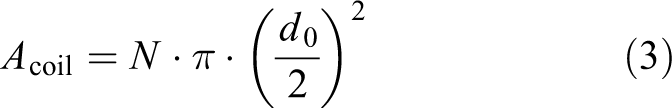
The whole thickness of the wires on the shaft section of the coil will be larger than the theoretical thickness because of the gaps between wires. When the coil is wound for 80 turns of wires, the actual thickness will be 0.7 mm larger than that by the theoretical value. So, the section thickness of a coil h can be obtained, as shown in formula (4)

The handheld electric drill used in the experiment is the same type as that used by doctors in orthopedic surgery. The width and length of the handheld drill are 30 mm and 80 mm, respectively. The device needs to be mounted on the handheld drill. Therefore, the size of the device should be according to the size of the electric drill. Based on the above analysis, the dimensions of pressure device are determined as in Table 1. The prototype of the device was prepared by 3-D printing, as shown in Figure 7.

The prototype of the pressure device.
Verify the electromagnetic force
A measuring experiment for the electromagnetic force was carried out. The schematic is shown in Figure 8. The prototype of the experiment is shown in Figure 9. The measurement platform is composed of a sleeve, winding, magnetic grid, force gauge, slide rail, ruler, power, and supported shelf. The dynamometer was fixed on the slide rail and can slide vertically on the slide rail. The magnetic grid was hung on the hook of a dynamometer. A ruler was placed beside the slide rail to measure the distance that the magnetic grid moves. The sleeve is held with the winding and it is made sure that the magnetic grid can move relative to the sleeve by the electromagnetic force when the coil is energized. A weight was hung under the magnetic grid to improve stability during the measurement.

Schematic for measuring the electromagnetic force.
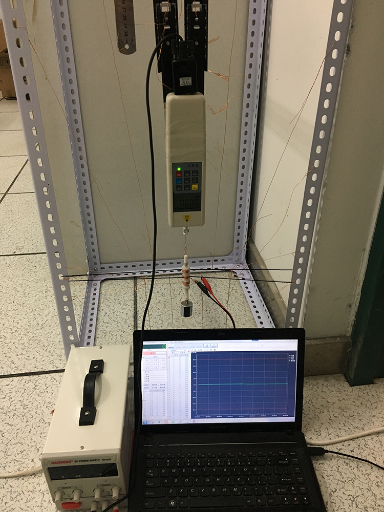
The experiment of measuring electromagnetic force.
The dynamometer is moved along the slide rail to different positions. Then, the value of force displayed by the dynamometer and its corresponding position by reading the scale of the ruler are recorded . Next, the experiment force of this device is drawn as the red curve in Figure 9. And the theoretical electromagnetic force simulated by Maxwell is drawn as the black curve in Figure 10. The curve obtained by the experimental measurement is obviously below the calculated curve. It can also be found that the force measured by the experiment is 31% lower on average than that by theoretical calculation.

Theoretical and experimental forces.

Expression (5) is the formula for the average relative error of the theoretical value to the measured value. Where
Simulation and optimization of the device
The magnetic force on the magnetic scale must be greater than the total weight of the magnetic grid, which ensures that the magnetic grid is kept in contact with the surface of the bone or plate while the drill working. Considering the actual force measured by experiment is 31% lower on average than that by theoretical calculation from Figure 10, the rate force of the device needs to multiply by a correction factor of 1.31. So, the required force can be obtained by equation (6)

where F
0 is the required force,
The aim of designing the device is to meet the rated electromagnetic force and minimize the fluctuation of force. The influences of various factors on the electromagnetic force were analyzed by orthogonal experiments. 29,30
From Figure 4, we can see that the fluctuation of force is related to cycle time and amplitude. The cycle time is influenced by the length of permanent magnets, and the amplitude is affected by the diameter of permanent magnets and the number of turns on the coil.
The smaller the weight of the device, the more advantageous it is. The aim is to minimize the weight of the device operated by the surgeon while measuring the depth when drilling bone.
The size of the device should be as small as possible and should match the hand drill. The minimum size of a cylindrical permanent magnet easy to get is the diameter of 2 mm and the length of 2 mm. According to formula (6), the required force is about 0.4 N. Based on the required force, the electromagnetic force can meet the requirement when the diameter of the magnet is greater than 5 mm, the length is greater than 5 mm, and the turns on coil should be greater than 70.
Three-factor and three-level orthogonal simulations were carried out based on the above by changing Dm , N, and L 1, as listed in Table 2.
Factor level.

The level of factors determined through preliminary tests is listed in Table 3
L 9 (33) Orthogonal simulation results.

As the boldface tentries shown in Table 3, the electromagnetic force that can meet the minimum required is five groups, test number is 5, 6, 7, 8, and 9. The value of S 2 reflects the amplitude of the electromagnetic force. The value of S 2 in the eighth test is the smallest. The aim of designing the device is to minimize the fluctuation of the force. So, the eighth group of parameters was selected as the optimal parameters of the magnetic scale. The parameters are as follows, the diameter of the permanent magnet is 7 mm, the length of each permanent is 5 mm, and the turns on the coil are 80.
After the orthogonal simulations, the method of range analysis was used to analyze the factors. The results are listed in Table 4. Ki is the sum of all results whose factor index is i, ki is the average of Ki . The symbol R is the range value of the orthogonal simulations. It can be obtained by the equation as follows
Comprehensive evaluation results.
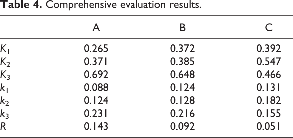

According to the theory of the range analysis, the factor which has larger R will have a greater effect on the optimal target. After analysis, it can be seen the degree of influence on electromagnetic force is the diameter of the permanent magnet, the turns of the coil, and the length of the magnet in order from largest to smallest. The optimized parameters of the device are listed in Table 5. The electromagnetic force of the device varies from 0.485 to 0.716 N; the fluctuation of the force is 0.231 N. And the variance of the force is 0.137.
The optimized parameters.

Based on the above, there are still some future works to be done. The circuit control needs to be designed. Then the fluctuation of electromagnetic force could be measured dynamically and reduces the variance by optimizing the structure of parts. The application for orthopedic surgery will be appealing if we complete these works.
Conclusion
A device for measuring the depth of the borehole in real time during orthopedic surgery was proposed. The function of the device for measuring the linear distance is based on the magnetic grid. Optimal parameters of the device were obtained by simulations and orthogonal analysis. The primary factor is the permanent magnet diameter. The optimized diameter of the permanent magnets is 7 mm, the length of the permanents is 5 mm, and the turns on the coil are 80. The electromagnetic force of the device varies from 0.485 to 0.716 N; the fluctuation of the force is 0.231 N. And the variance of the force is 0.137.
Footnotes
Declaration of conflicting interests
The author(s) declared no potential conflicts of interest with respect to the research, authorship, and/or publication of this article.
Funding
The author(s) disclosed receipt of the following financial support for the research, authorship, and/or publication of this article: This work was supported by “National Nature Science Foundation of China” [no. 51375180] and “Science and technology plan project of Quanzhou” [Z1624059].