
Abstract
This paper addresses the multi-physical field coupling problem of electromagnetic vibration in permanent magnet synchronous motors (PMSMs), and presents a fast calculation method for multi-harmonic decoupling of electromagnetic forces based on subdomain analysis and an equivalent ring model. This method breaks through the simplifying assumptions of traditional models regarding the non-uniform distribution of tangential electromagnetic forces and high-frequency nonlinear effects. By introducing a modified modal participation factor and an orthogonal anisotropic stiffness superposition criterion, it achieves a low-order modal frequency error of <7% for the stator-winding system and constructs a nonlinear mapping model between tangential forces and high-frequency vibrations. Compared with existing studies that neglect the non-uniform distribution of tooth surface forces and end constraint effects, the proposed method exhibits spectral localization accuracy better than 5% in the low-frequency band (<3 kHz) and improves computational efficiency by 80%. It significantly alleviates the modeling complexity of traditional finite element methods under multi-speed conditions and high-frequency prediction deviations. Experimental verification shows that this method can accurately characterize the electromagnetic vibration characteristics of motors, providing an effective technical approach for the early suppression of motor vibration and noise.
Keywords
Introduction
Vibration and noise are critical performance indicator for motors, with electromagnetic vibration and noise being the dominant component of overall motor vibration and noise.1,2 Accurate analysis and prediction of electromagnetic vibration during the design phase enable the implementation of effective measures to reduce vibration and noise at an early stage, thereby preventing severe vibration and noise issues in later stages. In addition, the accurate analysis of the electromagnetic vibration noise of the motor is also helpful to find the root cause of the vibration noise problem of the motor and an effective solution.3–5 Therefore, the accurate analysis and prediction of electromagnetic vibration noise of motor has important theoretical significance and engineering application value.
However, motor vibration and noise constitute a complex multi-physical-field problem, encompassing electromagnetism, mechanics, structural dynamics, and acoustics. The main research methods for electromagnetic noise of motors at home and abroad include AM, FEM, and experimental method. Torregrossa et al. 6 proposed a field reconstruction method for motor noise analysis and calculation. Li et al. 7 presented a hybrid subdomain model that takes into account the slotting effect, rotor significance and iron nonlinearity to calculate the magnetic field distribution of an internal permanent magnet motor. Ghalavand et al. 8 proposed an improved magnetic equivalent circuit method for calculating tooth and yoke flux densities in built-in PMSM. The nonlinear elements are used to consider the magnetic saturation of the core, and the iteration method is used to update these elements, but the model only considers the permanent magnet and the air gap permeability, and the calculation results are not accurate enough. The magnetomotive force permeability method can obtain a clear motor structure and the magnetic density of the air gap, and then the relationship with the electromagnetic force, which is widely used in electromagnetic vibration and noise analysis. 9
Regarding the finite element method and experimental approaches, Islam et al. 10 developed a 2D motor vibration model. While this model enables rapid stator vibration calculations, it struggles to accurately reflect real-world stator dynamics due to its neglect of complex stator tooth-winding structures and end-cover constraint effects. In terms of numerical prediction of vibration and noise, Torregrossa et al. 11 obtained the transfer characteristics of the stator structure by applying pulsed excitation through a force hammer, and then loaded the electromagnetic force at the center of the teeth to calculate the vibration of the structural surfaces. Santos et al. 12 established a numerical prediction model for switched reluctance motors with multi-physical fields (including circuit, electromagnetic force, vibration, and acoustic models), which is able to better reflect the main peaks and general trends of noise. However, the literature 13 and 14 both ignored the non-uniform distribution of electromagnetic forces along the stator surface by integrating the electromagnetic forces within a tooth pitch and then equating them to the tooth center. Kim et al. 13 and Sebastian et al. 14 used a similar method of equating the electromagnetic forces, and this type of force loading ignored the non-uniform distribution of the electromagnetic forces along the tooth surface of the stator and increased the error in the vibration and noise calculations.
The accurate calculation of stator natural frequency is the key premise for analyzing electromagnetic vibration of motor. The finite element method was used to study the influence of the stator core structure parameters on the stator natural frequency, and the accuracy of the finite element results was verified by the hammer method.15–17 Yu et al. 18 comprehensively considered the anisotropy generated by the stator teeth, winding, stator core and stator casing, and the natural frequency calculated by using the integral component exceeded the natural frequency based on the independent consideration of the stator core. The accuracy of the results is verified by numerical simulation and experimental measurement of a permanent magnet synchronous motor with 5 poles to 12 slots. Considering the moment of inertia and transverse shear deformation of the cylindrical casing, for improving the calculation accuracy of the stator intrinsic frequency, Xing et al. 19 analyzed in detail the effects of tooth foot and tooth shoulder, and proposed to model the stator core and stator casing as cylindrical casings, respectively, and to add axial rib structures on the inner and outer sides of the casings. At the same time, the rotational inertia and transverse shear deformation effects of the cylindrical casing are considered. Galerkin diffusion method and Rayleigh–Ritz method are used to discrete the vibration displacement of the continuous system. Based on the three-dimensional casing theory, the stator characteristic equation under free vibration is derived, and the natural frequency of the stator under anisotropic material is obtained.
Verma et al. 20 proposed an improved methodology for calculating the natural frequencies of stators in IPMSMs. This approach overcomes the limitation inherent in prior analytical methods, which simplistically treated the influence of stator teeth on natural frequencies as merely an additional mass effect. Subsequent studies21–24 employed the FEM to map electromagnetic forces onto structural models. These analyses examined the vibrational displacement and acceleration response of the stator outer surface under electromagnetic excitation, enabling accurate prediction of motor vibration performance. It is noteworthy that during motor operation, the tangential electromagnetic force, serving as the direct source of torque or thrust, exhibits a highly nonlinear relationship with electromagnetic state variables such as winding current and magnetic flux linkage. This nonlinearity arises primarily from factors including ferromagnetic saturation and harmonic effects, rendering traditional linear models inadequate for precise characterization.25–27 Consequently, nonlinear mapping models for the tangential electromagnetic force have been developed. These models aim to establish the nonlinear relationship between inputs and outputs, thereby laying the foundation for high-precision prediction, optimized design, and advanced control strategies. However, the development of such models involves highly intricate multi-physical field coupling, resulting in a complex modeling process and significant computational burden.
To address the issues in existing literature, such as insufficient accuracy due to model simplifications, neglect of structural constraints and force distribution characteristics, and low computational efficiency of the FEM, this study focuses on the multi-physical field coupling problem of electromagnetic vibration in PMSMs and proposes a multi-harmonic decoupling method for electromagnetic forces based on subdomain analysis and an equivalent ring model. This method abandons the simplifying assumptions of traditional models regarding the non-uniform distribution of tangential electromagnetic forces and high-frequency nonlinear effects. By introducing a modified modal participation factor and an orthogonal anisotropic stiffness superposition criterion, it controls the calculation error of the low-order modal frequencies of the stator-winding system within 7% and constructs a nonlinear mapping model between tangential electromagnetic forces and high-frequency vibrations. Compared with existing studies, this method achieves a spectral localization accuracy better than 5% in the low-frequency band (<3 kHz) and improves computational efficiency by 80%, effectively alleviating the problems of complex modeling and high-frequency prediction deviations in traditional FEM.
Analysis of electromagnetic force
In this paper, based on the classical Maxwell stress tensor method, the calculation of radial and tangential electromagnetic forces can be expressed as follows

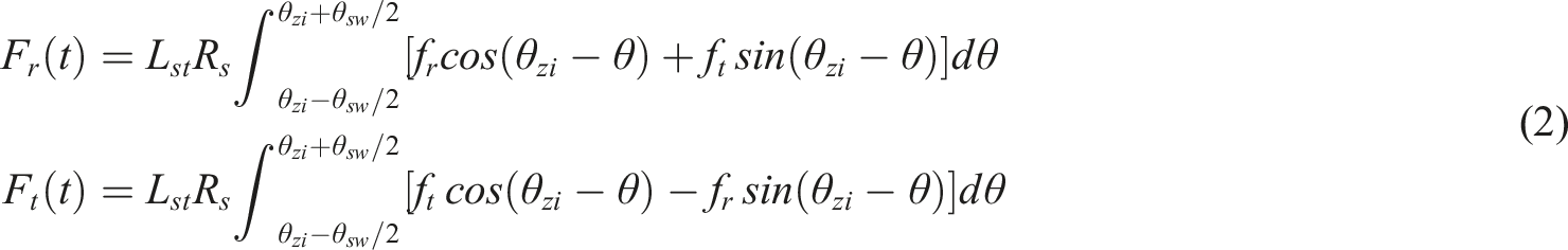
Figure.1 illustrates the analytical model of the PMSM, where: denotes the rotor position and the angle between the center line of the permanent magnet and the center line of a certain tooth is α. Assuming that the magnetic permeability of the rotor core tends to infinity and the magnetic pressure drop in the stator core can be neglected, the distribution of the magnetic density in the air gap in the radial and tangential directions can be expressed as Analysis model of surface mounted permanent magnet synchronous motor. Main parameters of the motor.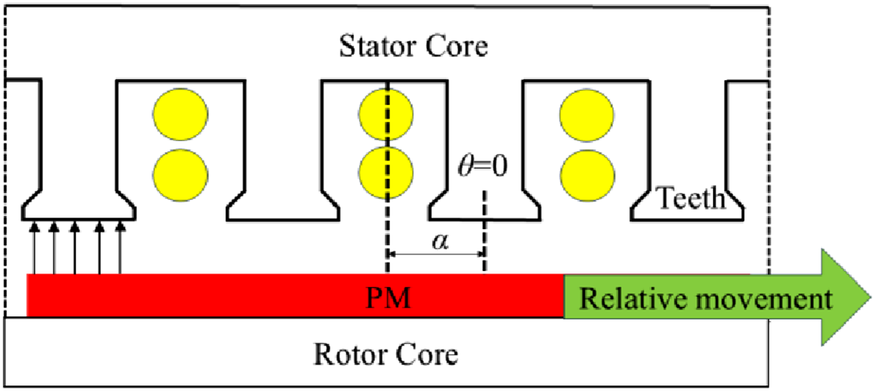
As shown in Figure 2, under the slotted condition, due to the complex geometric structure of the stator tooth shape, the magnetization curve shows obvious demagnetization under the action of current. In contrast, under unslotted conditions, the magnetization effect of the magnet is more ideal, and no obvious demagnetization phenomenon is observed. However, both of them show obvious nonlinear characteristics in the magnetization process. Magnetizing curve under slotted and unslotted conditions.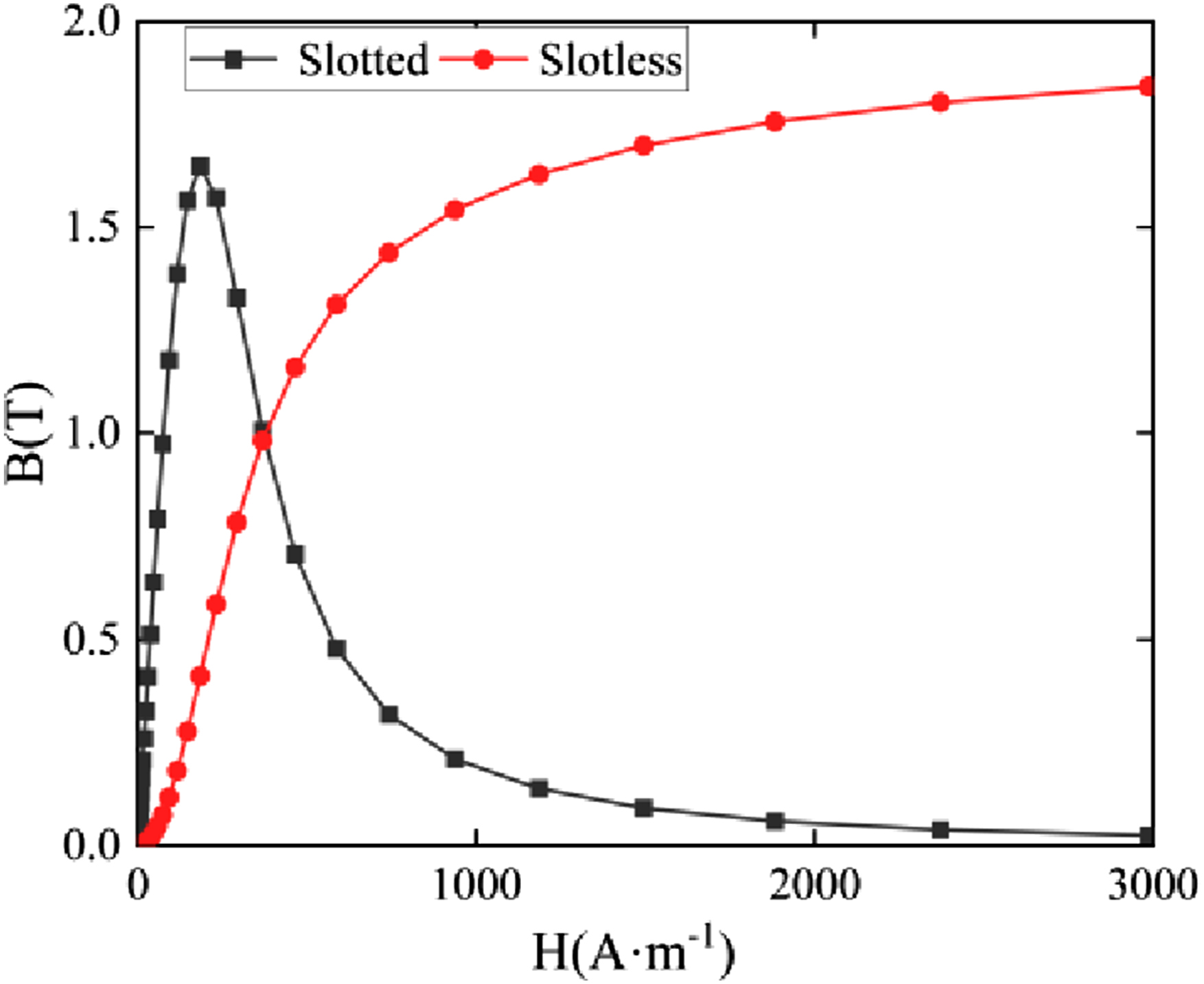
Calculation of no-load air-gap MMF
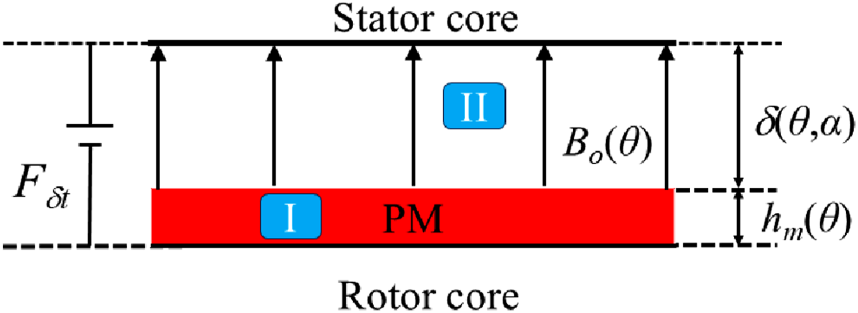
As shown in Figure 3, the slotless permanent magnet synchronous motor can be modeled based on the subdomain method as consisting of two subdomains: the permanent magnet subdomain I and the air gap subdomain II. Among them, the air gap magnetic flux distribution under no-load conditions F1(θ) and the magnetic flux density distribution in the no-load air gap B0(θ) is the key quantity; δ represents the air gap length. h
pm
indicates the axial length of the permanent magnet Motor structure diagram without slots.

Here, F1r(θ), F1t(θ), B
or
(θ) and B
ot
(θ) represent the radial and tangential components of F1(θ) and B
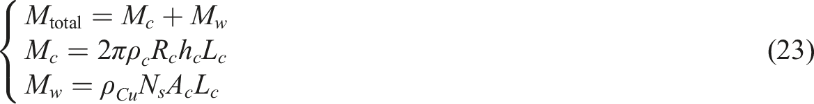
o
(θ), respectively, and j is the imaginary operator. Although F1r(θ) and F1t(θ) contain the same harmonic components, they differ in amplitude and phase. Using subdomain methods,27,28 B
o
(θ) can be quickly and accurately derived for the tree-free sloth model. Moreover, the MMF F
1
(θ, t) can be expressed as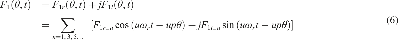
Calculation of air-gap magnetic density
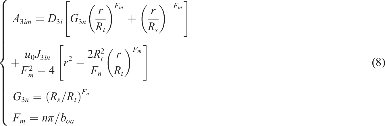
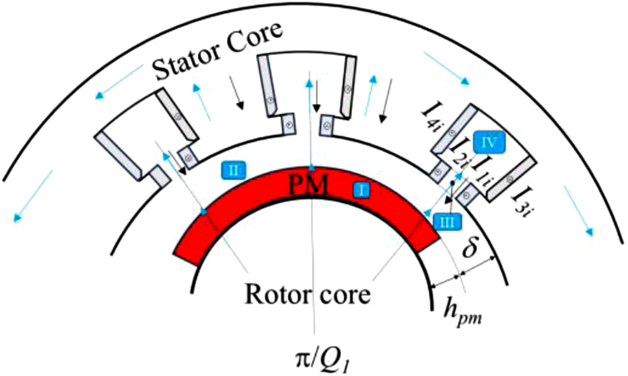
Figure 4 shows the slot structure of the PMSM, where Q1 represents the number of slots. The range of tooth centerline offset is set to be between -π/Q1 and π/Q1, which is the arc of the permanent magnet pole. This model divides the motor into four sub-regions: the permanent magnet region I, the air gap region II, the slot opening region III, and the slot cavity region IV. The stator tooth saturation effect can be simulated by applying an equivalent surface current on both sides of the tooth to generate an opposing magnetic field. The calculation follows the iterative method described in reference 20. Usually, the saturation effect on both sides of the slot opening is ignored and is regarded as air medium. Based on the equivalent surface current on both sides of the slot opening, the vector magnetic potential A
z3i
in region III can be solved according to the expression given in reference 29 The motor has a tooth slot structure diagram.


In slot-shaped subdomain IV, the magnetic vector potential A
z4i
can be directly solved analytically. By solving the coupled system of equations established through the boundary conditions of each subdomain, the undetermined coefficients Q
3i
and D
3i
in subdomain III, as well as the undetermined coefficients in other subdomains, can be determined. Additionally, the equivalent air-gap permeance λ(θ) within the pitch period can be obtained by calculating based on the air-gap flux density distribution B
δt
(θ), which needs to be analytically characterized within the range of a single pitch angle

The air gap permanence λ(θ) can also be represented as
Calculation of MMF of armature reaction
The fundamental magnetomotive force and the V-harmonic magnetomotive force generated by the three-phase symmetric current are, respectively

The three-phase synthesized magnetomotive force of the stator winding can also be expressed as
Calculation of air-gap flux density
Based on the magnetic flux permeability method, this paper derives the radial and tangential components of the air-gap magnetic flux density under no-load conditions, as well as the air-gap magnetic flux density due to armature reaction. The relevant formulas are presented as follows
Therefore, the air gap flux density on the load is

Verification of calculation methods
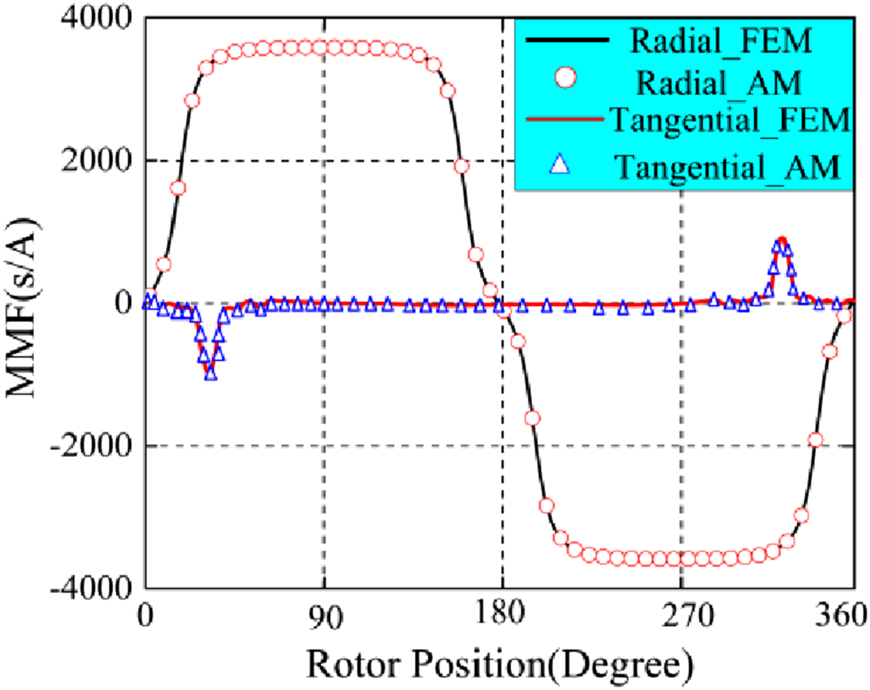
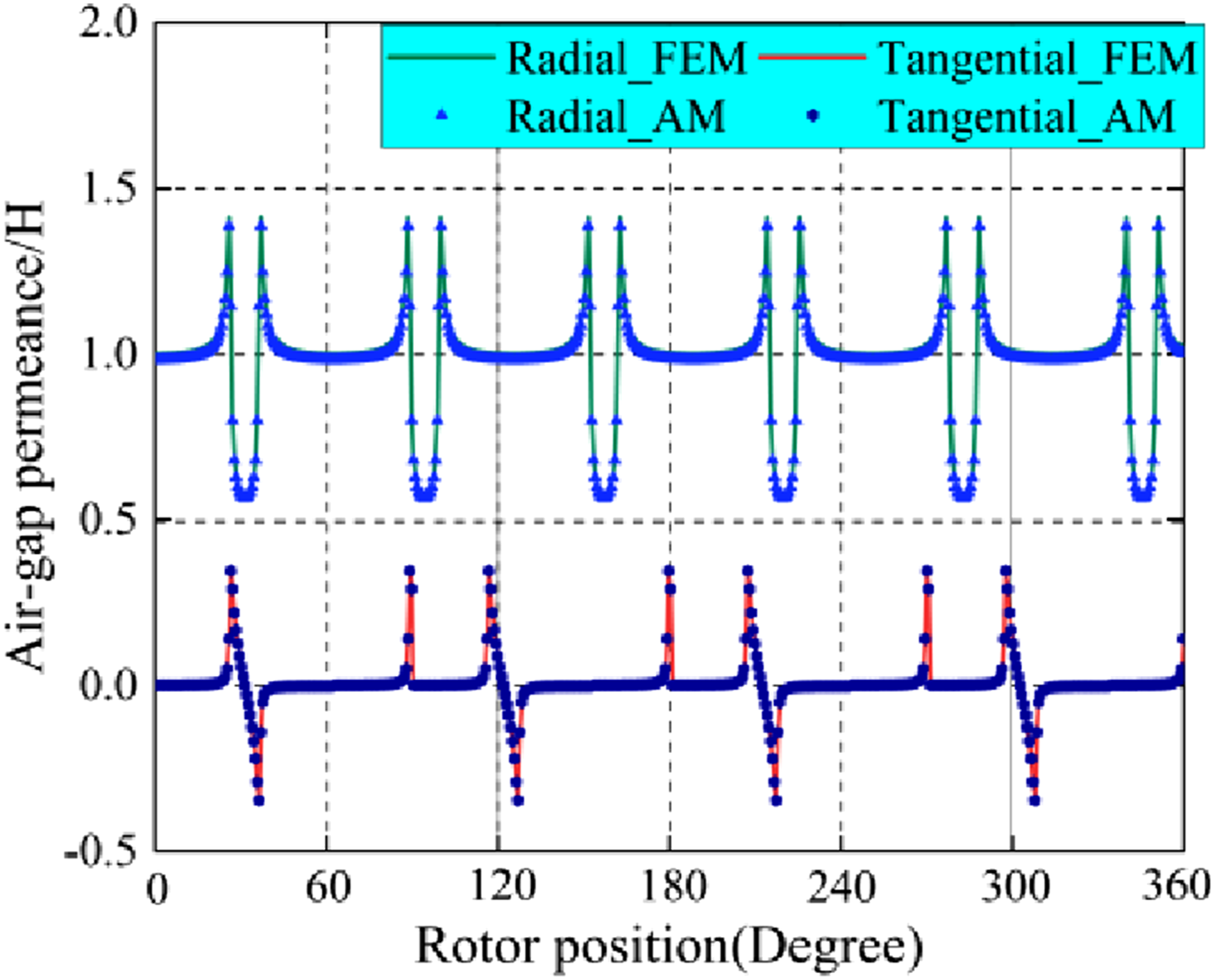
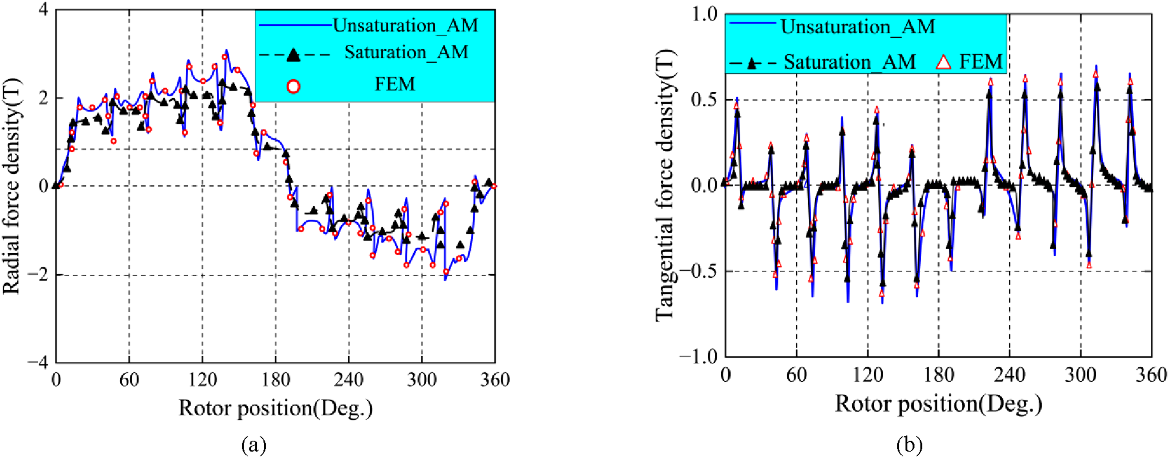
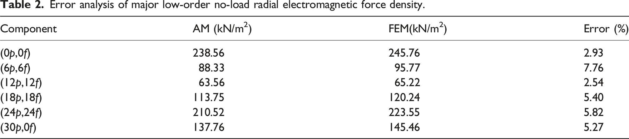
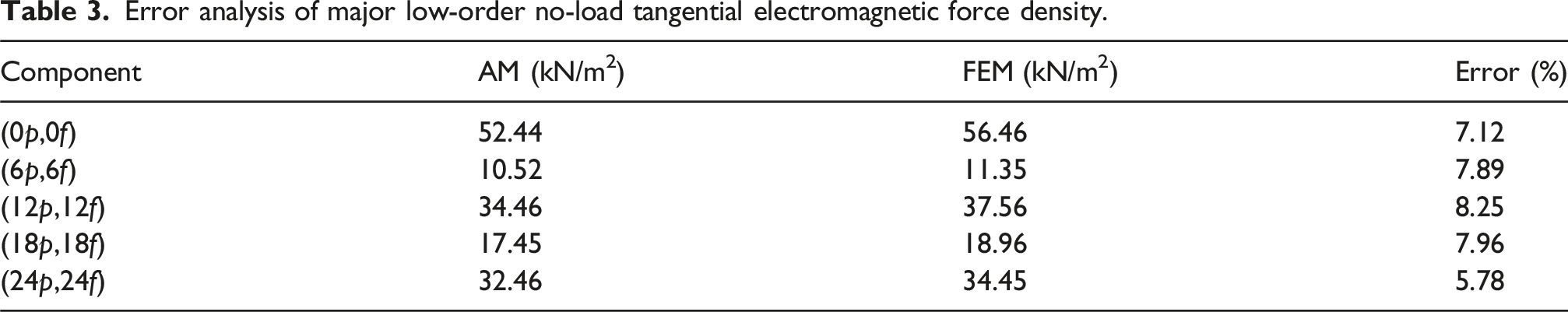
This paper validates the electromagnetic force characteristics of surface-mounted permanent magnet synchronous motors through comparisons between the AM and FEM (Figure 5). Under no-load conditions (Figures 6, 7 and 8), AM accurately characterizes the periodic permeability distribution modulated by cogging effects, with the radial and tangential electromagnetic force density distributions showing high consistency with FEM in both amplitude and harmonic components. Figure 9 compares the electromagnetic force density of AM (including unsaturated and saturated cases) with that of FEM under a 50 Nm load. The unsaturated AM, due to the neglect of core saturation, deviates significantly from FEM; the saturated AM, considering the saturation effect, shows a trend closer to FEM, verifying the necessity of saturation correction in improving the accuracy of AM under load conditions. Error analysis (Tables 2 and 3) shows that the maximum calculation errors for the low-order harmonics of radial force (6p-6f, 24p-24f) and the dominant harmonics of tangential force (12p-12f) are controlled within 8.5% and 8.25%, respectively. The study reveals the impact of model simplification assumptions on high-frequency vibration prediction, indicating that modified mode participation factors are required to characterize the local bending vibration features at high frequencies. This work confirms the engineering applicability of the analytical model in electromechanical coupling characteristic analysis. Finite element model of PMSM. No-load air gap MMFs for PMSM. Air gap permeability of PMSM. Comparison of the AM method and the FEM method for radial and tangential electromagnetic force densities under no-load conditions. Comparison of the AM method and the FEM method for radial and tangential electromagnetic force densities under a load of 50 Nm. Error analysis of major low-order no-load radial electromagnetic force density. Error analysis of major low-order no-load tangential electromagnetic force density.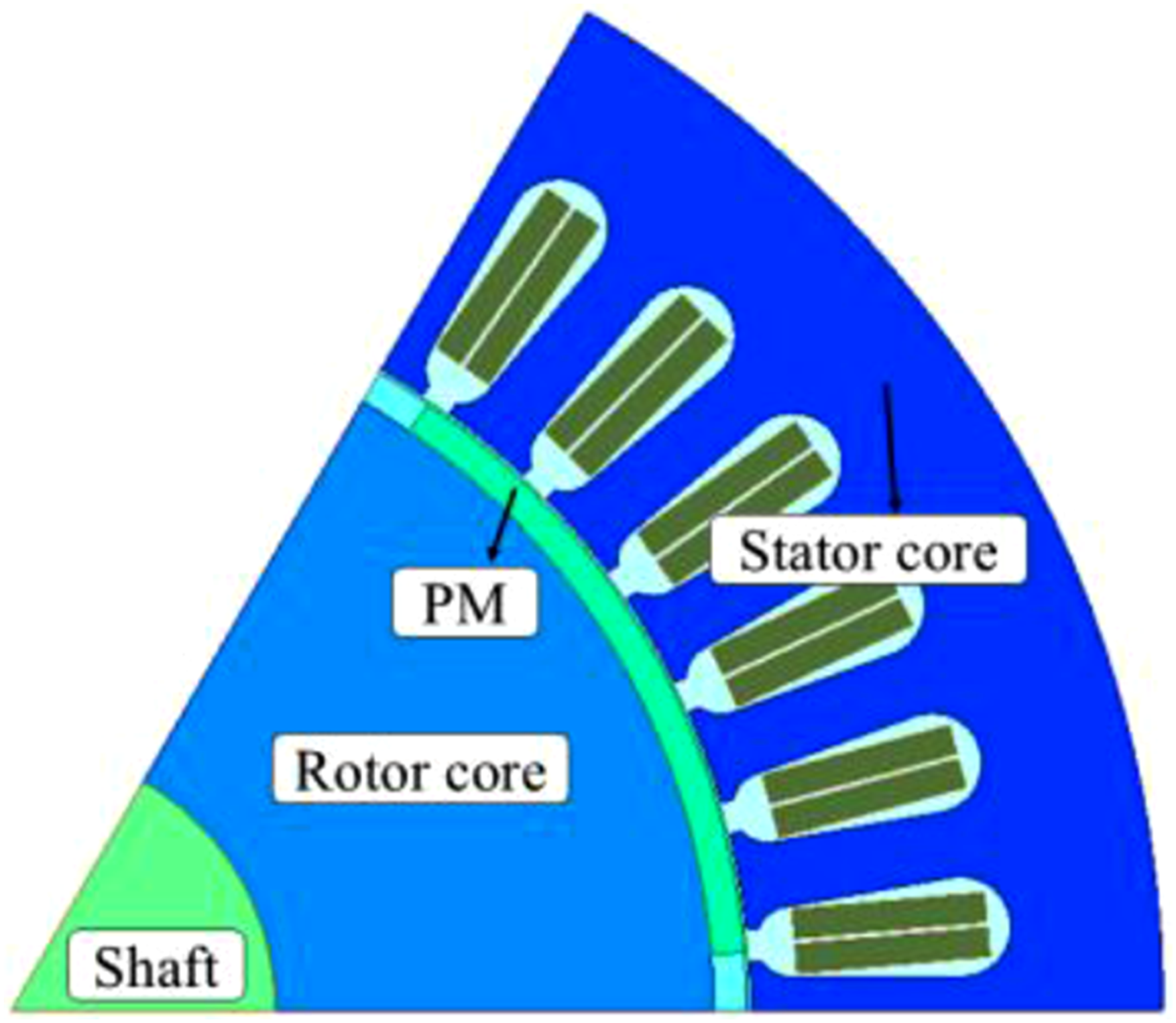
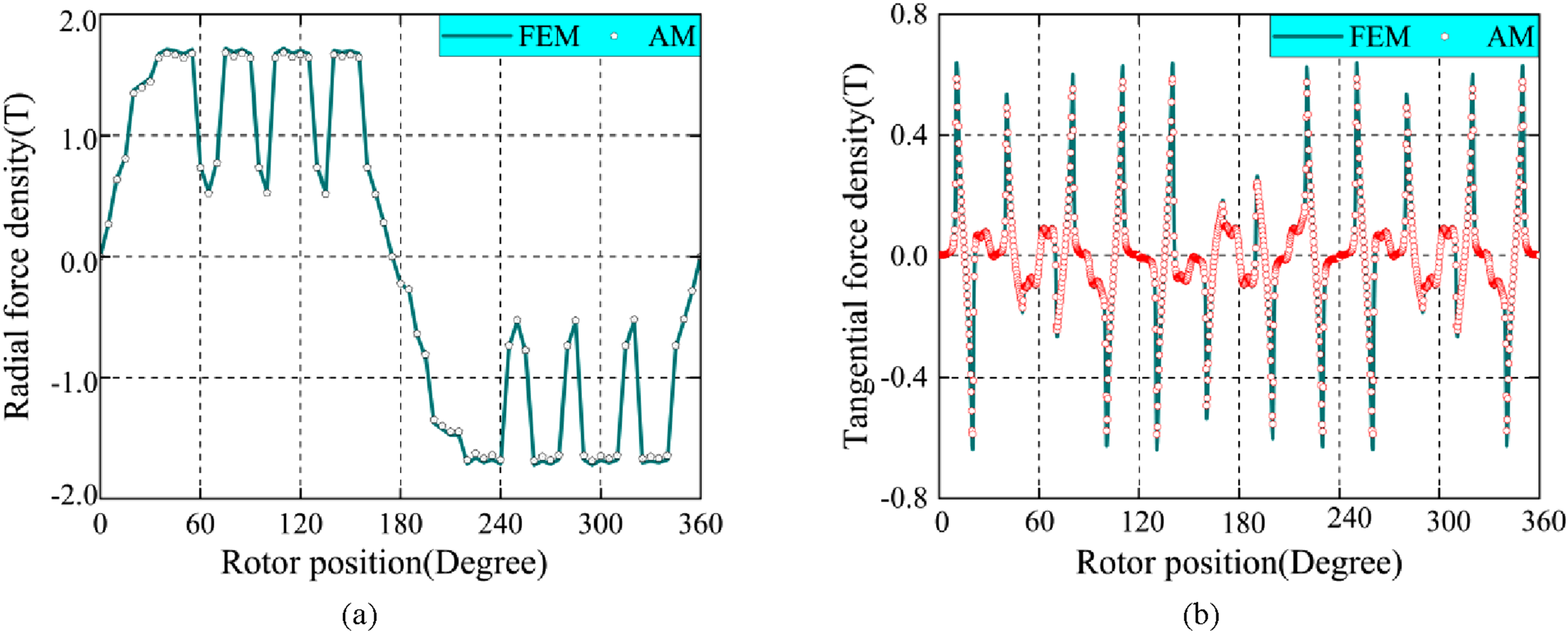
As shown in Figures 9 and 10, when the frequency exceeds 5000 Hz, the radial electromagnetic force decreases significantly, while the tangential electromagnetic force increases, thereby exacerbating the lever arm effect caused by the tangential electromagnetic force.
31
Therefore, the influence of tangential electromagnetic force should not be neglected. The spatial distribution of electromagnetic force under load conditions. (a) Radial; (b) Tangential.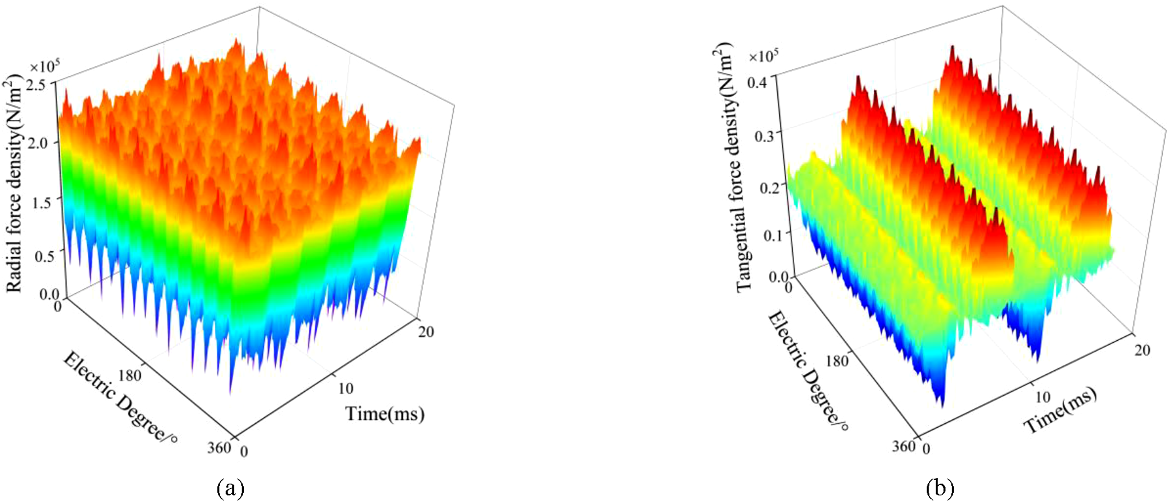
Calculation of stator natural frequency
Calculation of natural frequency of equivalent stator core with windings
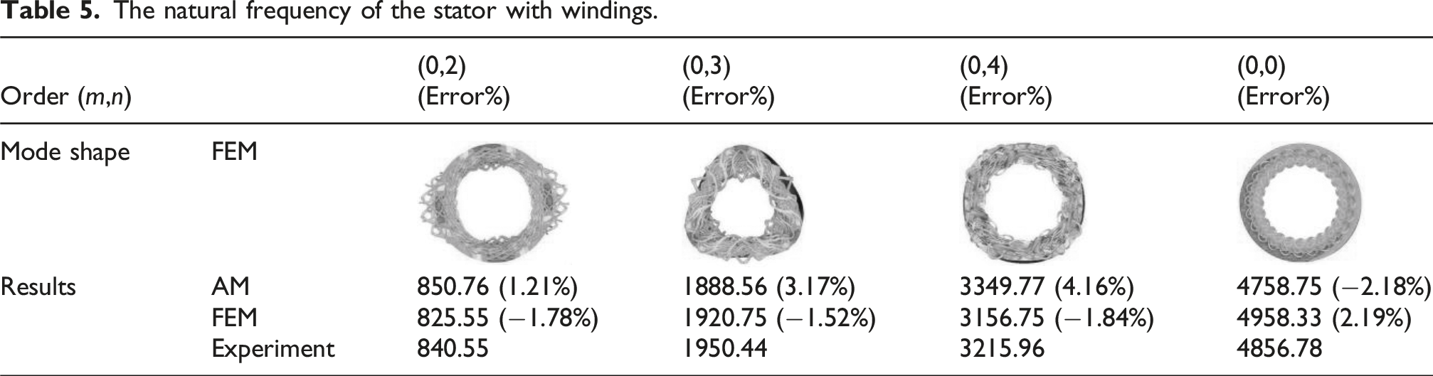
To address the limitation of traditional methods in neglecting the integrated stator anisotropic characteristics, this study presents an analytical method for the natural frequency of the stator-winding system based on an equivalent cylindrical model. By decomposing the stator core into a double-ring system consisting of a stator ring and a winding equivalent ring, and synthesizing the stiffness contributions and mass distribution characteristics of both, the inner diameter parameter of the equivalent ring is determined based on the stiffness equivalence criterion, achieving high-precision solutions for low-order circumferential modal frequencies. This method effectively characterizes the system’s anisotropic characteristics through equivalent parameter reconstruction and significantly improves the calculation accuracy of radial vibration modes (Figure 11). Schematic diagram of stator and equivalent stator.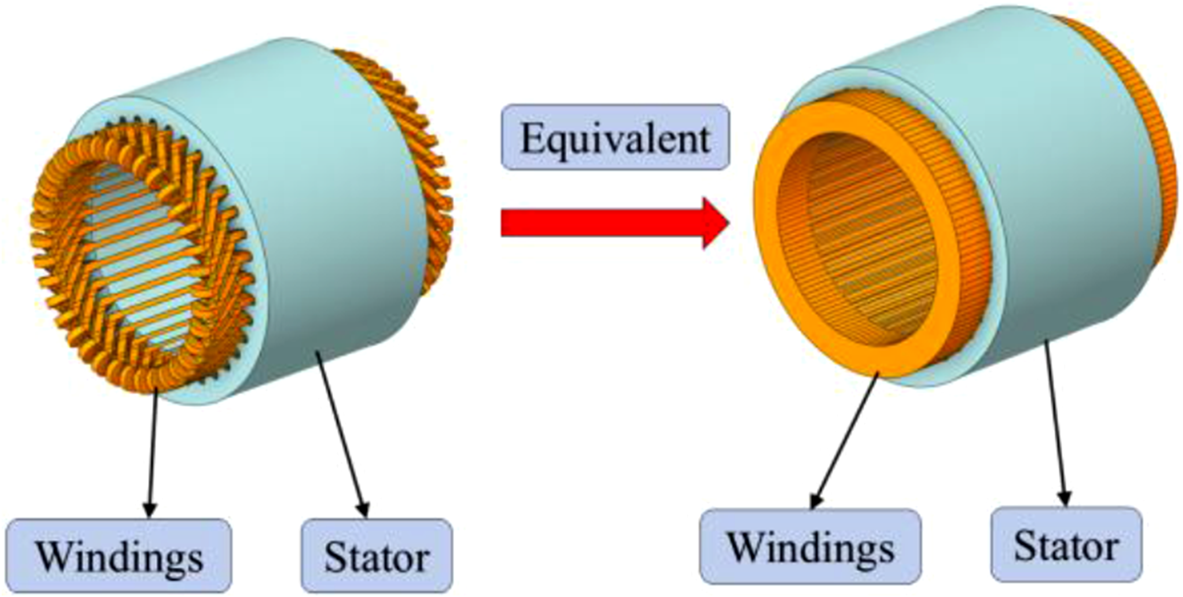
Anisotropic stiffness correction
As an anisotropic functional layer, the winding induces spatial heterogeneity in the stiffness of the stator structure. In this study, the winding is modeled as an axial additional layer structure, and its stiffness properties are characterized using orthotropic constitutive relations. Through the stiffness superposition principle, a modified equivalent stiffness matrix of the stator is derived.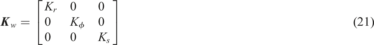
The stiffness of the stator core is
Intrinsic frequency correction formula
After considering anisotropy, the intrinsic frequency formula is extended to 20
γ(n) is the participation factor of the mass distribution mode
The stator core investigated in this paper has a relatively short axial length (the ratio of its axial length to the stator outer diameter is less than 0.5), and its vibrational deformation primarily occurs in the circumferential direction. Therefore, the analysis in this paper is mainly based on the circumferential modes of the stator. Neglecting the effect of damping, the natural frequencies corresponding to the circumferential modes of the stator core are
The natural frequency of the stator.
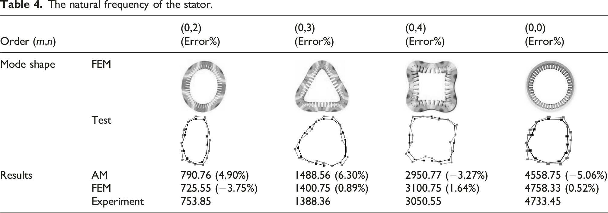
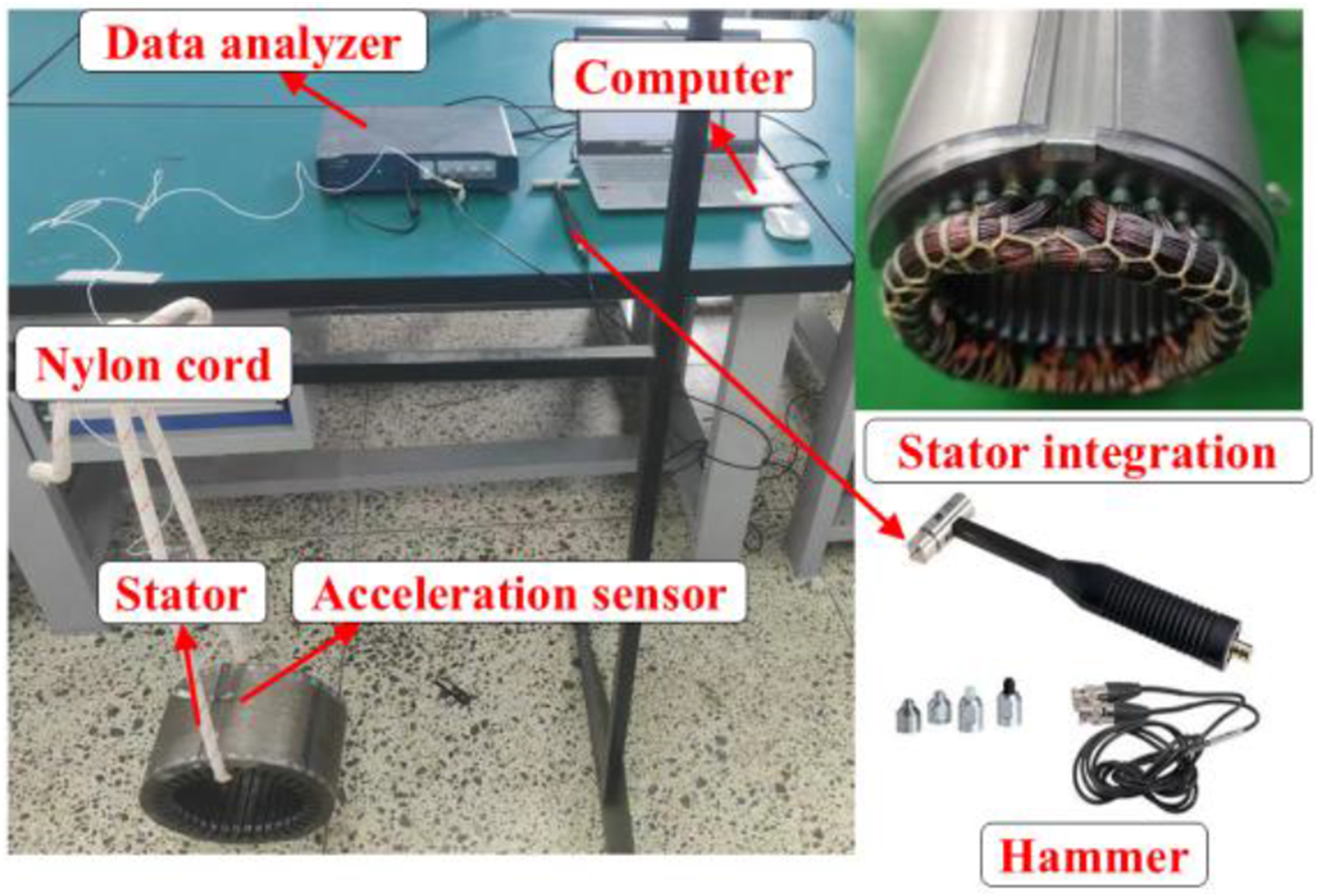
Layout diagram of modal hammer experiment.
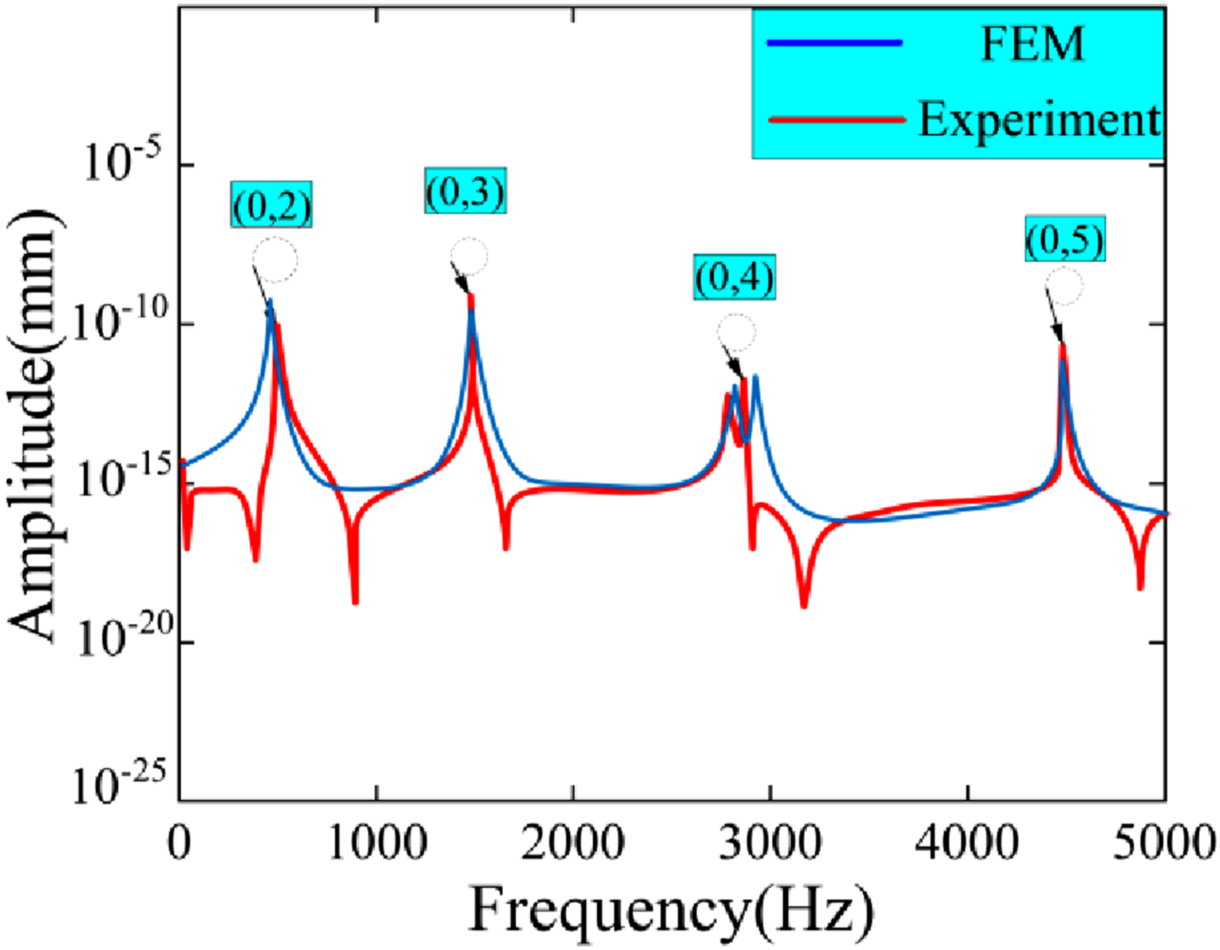
Comparison of amplitude frequency response functions between experimental and analytical methods.
The natural frequency of the stator with windings.
Calculation of electromagnetic vibrations
The radial force density f
r
(θ,t) and the tangential force density f
t
(θ,t) are, respectively, mapped to the structural mode space. The modal force expression is
The vibration displacement response is excited by both radial and tangential forces, and its frequency-domain expression is
The additional torque M
t
generated by the tangential force can be equivalently regarded as a local inertial load
The excitation efficiency of the tangential force on the higher-order modes needs to be determined through the corrected modal participation factor γ(n)
To quantify the sensitivity characteristics of vibration to tangential force, this study conducted a comparative analysis of the radial and tangential structural responses under unit force wave excitation, and constructed a transfer function as the sensitivity evaluation index. This function achieved the quantitative characterization of the electromagnetic force-vibration coupling effects in different directions through normalization processing (Figure 14) The modal participation factor of the vibration response of PMSM.
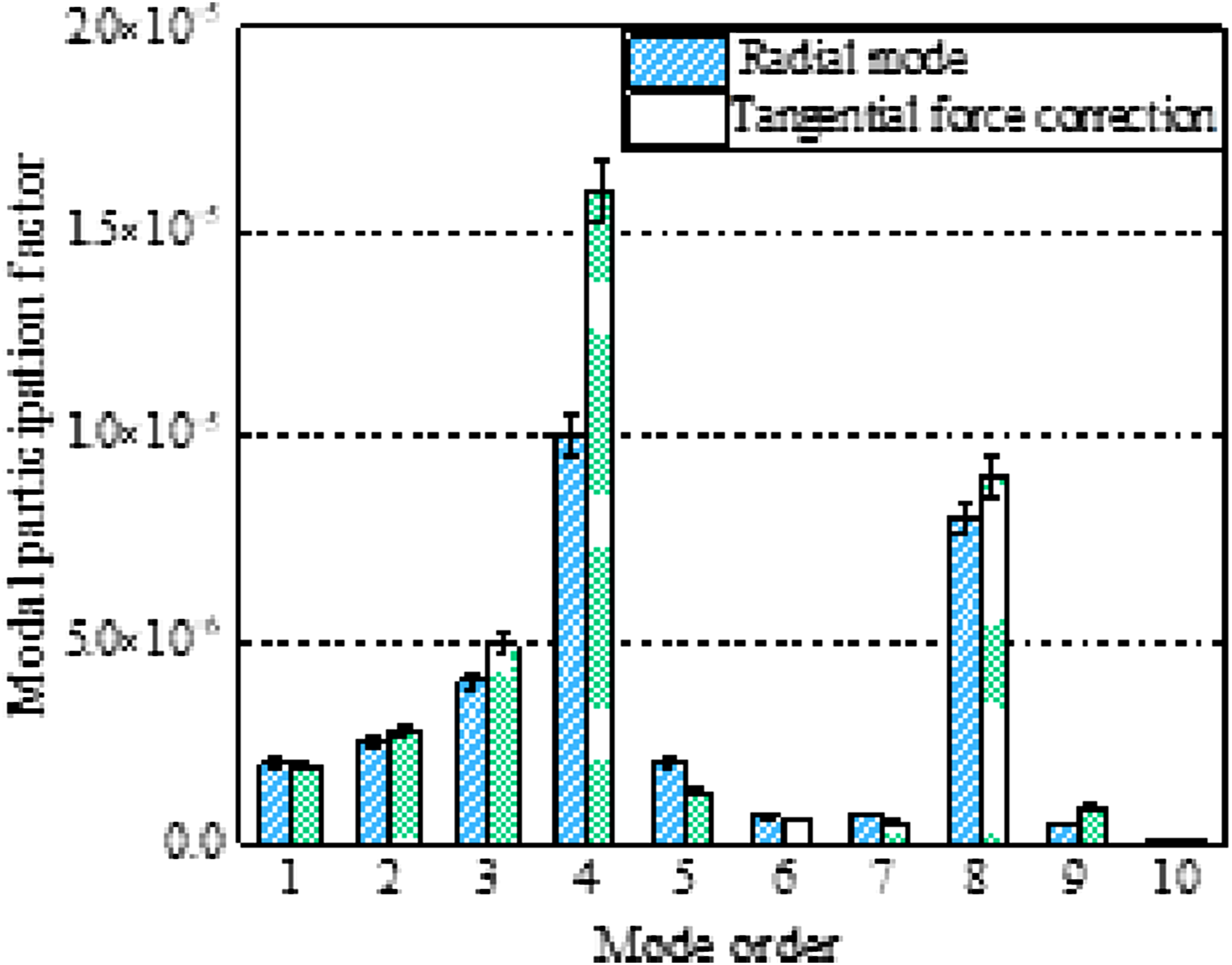
Figure 15 shows the amplitude-frequency response characteristics of the transfer function under different order force wave excitation. In the low-frequency range (<2000 Hz), the response spectra of each order of force waves are prominent, matching well with the low-order modes (such as 2nd, 3rd, and 4th orders) of the stator’s natural frequencies, indicating that the structure is sensitive to low-order electromagnetic force excitation; in the high-frequency range (>3000 Hz), the amplitude decays significantly, mainly due to the linear approximation assumption of the model for the damping of high-order modes and the lever effect. Among them, the zero-order mode (d) presents a wideband response at the fundamental frequency, reflecting the overall rigid body motion characteristics of the stator. Amplitudes of the transfer functions with respect to frequency. (a) 2nd force. (b) 3rd force. (c) 4th force. (d) 0th force.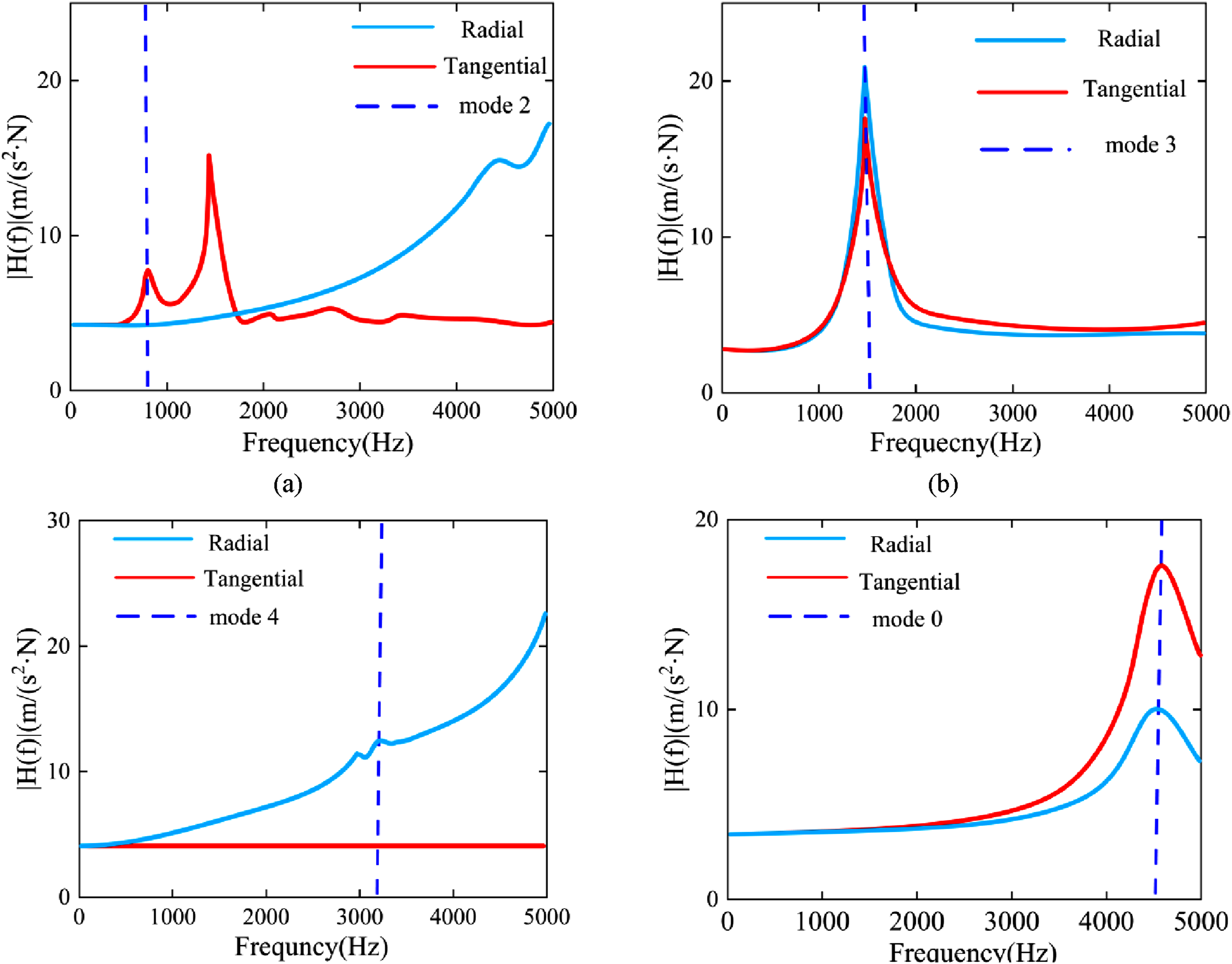
This paper maps the radial and tangential electromagnetic force densities into the structural modal space using the modal superposition method. Based on the modal forces and the stiffness, mass and damping characteristics of each mode, the vibration responses of each mode are superimposed to obtain the overall vibration characteristics of the system.34,35
For a mechanical system with mass M
n
, stiffness K
n
and damping coefficient C
mn
, when subjected to a periodic alternating force with amplitude F
a
, the vibration process can be expressed as

This study proposes a method for analyzing the stator vibration characteristics based on the principle of equivalent electromagnetic force density. As shown in Figure 16, the radial and tangential electromagnetic forces are equivalently applied to the centerline of the inner surface of the stator teeth. By multiplying the center electromagnetic force density of the tooth section with the tooth surface area, the electromagnetic force load of each tooth can be obtained. Based on this model, the vibration spectral characteristics under multiple rotational speeds were calculated using both the analytical method and the finite element method. The results showed that there was a certain deviation in the amplitude of the vibration acceleration spectra obtained by the two methods, but they presented a high degree of consistency in the spectral distribution pattern and the main harmonic components. It is worth noting that the vibration response curve obtained by the analytical method accurately reproduced the characteristic vibration modes and the distribution of resonance speed bands of the stator structure, verifying the engineering applicability of this equivalent loading method. The study shows that the vibration response prediction method based on the principle of linear superposition can significantly improve the efficiency of motor vibration characteristic analysis while ensuring the calculation accuracy, providing an effective technical approach for the rapid estimation of motor vibration noise. Comparison of FEM and AM for integrated stator surface vibration acceleration at different rotational speeds. (a) FEM loadedd; (b) AM loaded.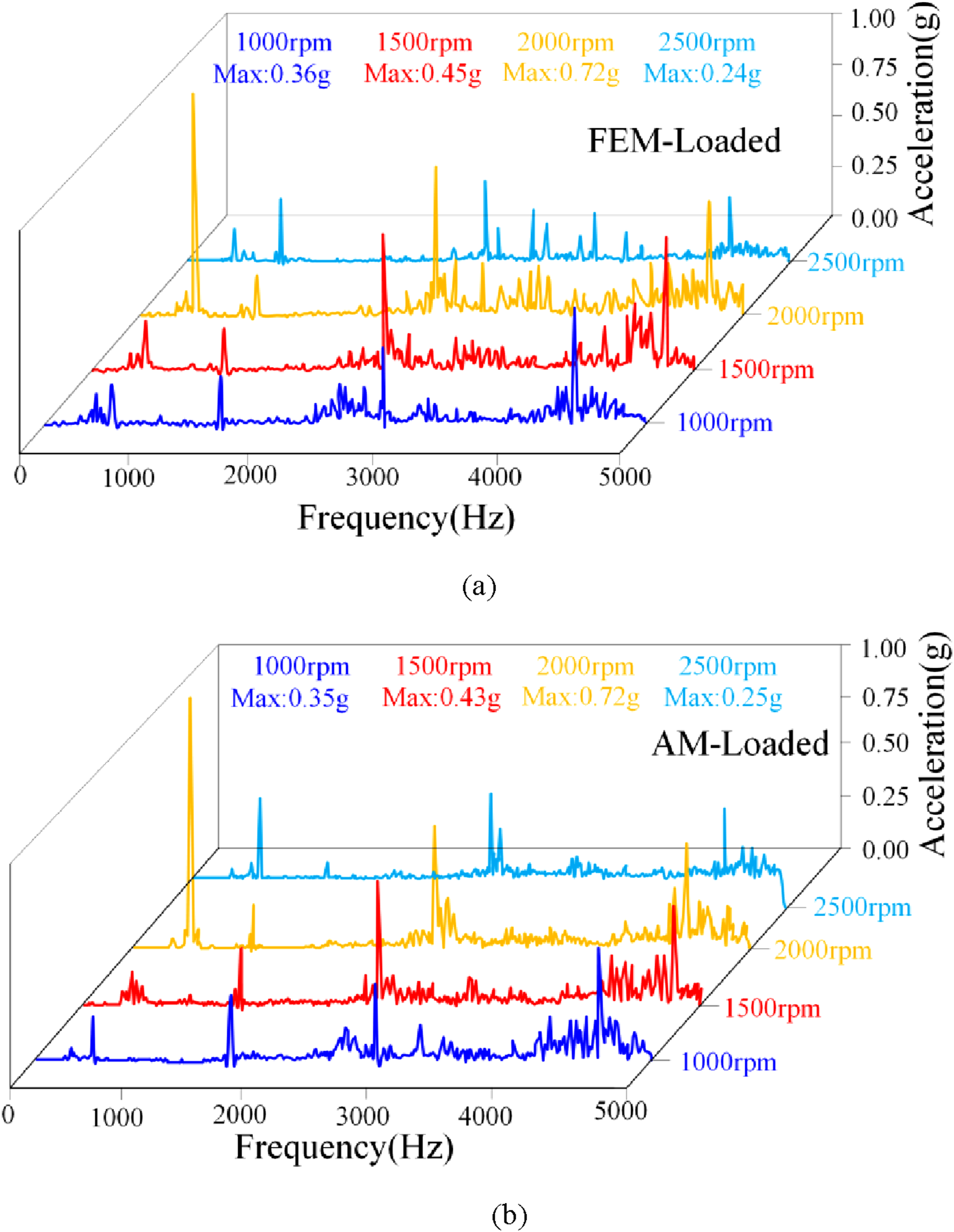
As shown in Figure 17, quantitative comparative analyses were conducted in this study on the computational efficiency of physical indices related to the electromagnetic vibration prototype. On the finite element simulation platform equipped with a 2.96 GHz processor and 32 GB memory, the AM proposed in this study demonstrated significant efficiency advantages compared with the traditional multi-physics coupled finite element method. Experimental data show that the total calculation time of the AM method was reduced by more than 80%, especially in the motor optimization design stage. By eliminating the complex 3D modeling process, the AM method effectively avoids the time costs of mesh generation and parameter debugging in traditional numerical simulation, thereby significantly shortening the design iteration cycle. Such high efficiency makes it of great application value in engineering scenarios requiring rapid parameter optimization. The calculation time for various physical indicators.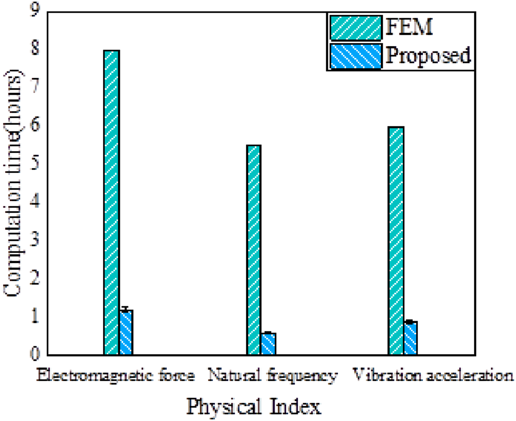
Conclusion
This study addresses the multi-physical field coupling problem of electromagnetic vibration in permanent magnet synchronous motors (PMSMs) and proposes a fast calculation method for multi-harmonic decoupling of electromagnetic forces based on subdomain analysis and an equivalent ring model. This method breaks through the simplifying assumptions of traditional models regarding the non-uniform distribution of tangential electromagnetic forces and high-frequency nonlinear effects. By introducing a modified modal participation factor and an orthogonal anisotropic stiffness superposition criterion, it controls the low-order modal frequency error of the stator-winding system within 7% and constructs a nonlinear mapping between tangential forces and high-frequency vibrations. Compared with existing methods, it achieves a spectral localization accuracy better than 5% in the low-frequency band (<3 kHz), improves computational efficiency by 80%, effectively alleviates the modeling complexity and high-frequency prediction deviations of traditional finite element methods, and experimental verification confirms its ability to accurately characterize the electromagnetic vibration characteristics of motors.
In addition, the future research can be extended to multiple types of motors, explore the strong coupling mechanisms of multi-physical fields, integrate with intelligent algorithms into design platforms, and delve into the nonlinear vibration mechanisms in high-frequency bands to support wide-frequency vibration control.
Footnotes
Acknowledgments
First, our deepest gratitude goes to the anonymous reviewers for their careful work and thoughtful suggestions that have helped improve this paper substantially. Second, we thank Dr Zhuo Xu for his technical assistance.
Funding
The authors disclosed receipt of the following financial support for the research, authorship, and/or publication of this article: This study was supported by The authors gratefully acknowledge the financial support received from National Natural Science Foundation of China (Grant No. 52405136) and Zhejiang Provincial Natural Science Foundation of China (Grant No. LQ23E050018) and Wenzhou Major Scientific and Technological Innovation Research Project (Grant No. ZZG2023003).
Declaration of conflicting interests
The authors declare that they have no known competing financial interests or personal relationships that could have appeared to influence the work reported in this paper.