
Abstract
Wear of wheels and rails is a major problem in railway transportation industry. Solid lubricants constitute a cost-efficient alternative to control wear and friction at the wheel–rail interface, especially when a fine-tuned balance between traction force and energy consumption is sought. In this work, composite friction modifiers (CFMs) composed of a vinyl ester matrix reinforced with molybdenum disulfide and carbon nanotubes were developed. The total solid additive content was less than a half in comparison with a commercial product available on the market, which was used as a reference. A benchmarking study of the CFM was carried out by means of tribological tests in a twin-disc machine at a contact pressure of 1.1 GPa and different slip values. The results indicated that the developed CFM reduce coefficient of traction by 10% compared to unlubricated conditions that is similar to the reference. However, the total mass loss of steel components due to wear under CFM lubrication was lower than in the reference test.
Introduction
Wear of railway systems costs millions of dollars per year globally. The total annuity cost/meter for rail maintenance of a non-lubricated 12 million gross tons transportation system is US$54, which can be as high as US$1.5 million a year for a 30 km line. 1 Furthermore, environmental burdens caused by wear and slip due to noise and so on are also an important issue, which have strong impact on the society. Usually these problems are addressed by application of lubricants and friction modifiers (FMs) to the interface between a wheel and a rail. An FM is a substance deliberately added as a layer into the wheel and rail contact, which helps to maintain stable coefficient of friction (COF). Depending on the level of COF FMs can be classified into three categories 2 : low-FMs (COF < 0.2), high-FMs (COF from 0.2 to 0.4), and very high FMs or friction enhancers (applied to increase adhesion, COF > 0.4).
The most common form of FM is a grease, which is poured in certain critical points on the rail way using a dosage system and spread over the rails by rolling wheels. Previous studies revealed non-straightforward effect, which grease FMs may have on the wear rate of rails. Maya-Johnson et al. reported that the wear rate increased in the tests where an FM was added after an initial stage of 4000 dry cycles. 3 This was associated to the cracks formation during the dry stage followed by accelerated crack growth and flaking due to the effects induced by the FM entering into the original cracks. To overcome these and other shortcomings of grease lubrication in an open tribological system such as contamination by solid abrasive particles (sand, wear debris, and solid residuals) and corrosive substances (water, other liquids, etc.), 4 non-uniform distribution on the rail, the need of a special infrastructure and so on, solid FMs have been developed recently. Solid FMs are usually composed of a polymer matrix with various dispersed solid fillers and fabricated in a solid bar (stick) form factor. Such solid composite FM (CFM) is applied onto the flange of the wheel or the rail by pressing the bar against the sliding surface. This creates a rather uniform surface film which is less prone to trap solid particles from the environment and to migrate away from the wheel flange 5 than grease.
Although there are various commercial solid FMs on the market for the wheel–rail contact, many aspects of their composition and performance need to be improved. So far, there has been only a limited volume of the literature focused on this topic. 5 –10 It was found that the solid FMs can help controlling rail corrugation 11 and tribo-induced noise. 12 Fletcher and Beynon 13 carried out a preliminary study into the implications of the change in lubrication method from grease to solid for rail rolling contact fatigue but the chemical composition of the bars was not reported. In contrast to grease, application of dry film top-of-rail FMs was shown to reduce crack growth and extend grinding intervals. 14 Despite the growing use of nanomaterials such as carbon nanotubes (CNTs) as lubricant additives, their application to the CFM for the wheel–rail contact has not been extensively studied so far. Chen et al. 15 reported the tribological properties of a lubricant doped with multi-walled CNTs (MWCNTs) modified with stearic acid by using a pin-on-plate testing machine. In other work, Khalil et al. 16 studied the tribological properties of two lubricating oils by using MWCNTs as additives at different concentrations (0.1, 0.5, 1, and 2 wt%). Friction and wear tests were performed using a four-ball tribometer. The results showed that the addition of MWCNTs to the oils reduced the COF and provided anti-wear properties. The authors found that adding MWCNTs to the fully formulated mineral oil led to decreasing wear on 39–68% and COF on 49–57% in comparison with the non-additivated commercial oils. Cornelio et al. 17 evaluated the tribological properties of single-walled CNTs and MWCNTs functionalized with carboxylic acid as lubricant additives dispersed in oil at different concentrations (0.01 and 0.05%) under rolling-sliding conditions in a twin-disc testing machine. They found that the presence of CNTs led to a decrease in the COF and in the wear rate. In the light of the above findings, it is reasonable to suggest that addition of CNTs to CFM can have synergistic effect on improvement of its friction and wear due rheological, and chemical mechanisms as well as through the improvement of heat dissipation.
In this work, we developed a new CFM functionalized with CNTs which were originally synthetized and characterized by the authors. The lubrication mechanisms of the CFM were investigated in a benchmark study using a commercial CFM as a reference.
Experimental
Materials
Three materials were studied in this work: a reference commercial FM (from now on “commercial”) and two new CFMs (molybdenum disulfide -MoS2- and MoS2-CNTs). The commercial lubricant bar was supplied by a train operator. The general microstructure of the commercial sample was analyzed using scanning electron microscope (SEM) and light optical microscope. The amount of solid reinforcements was analyzed by removing the matrix during burning tests in an oven at 650°C, in which the sample was weighted and then put in an oven during 4 h to eliminate the polymeric components leaving the mineral reinforcements unaffected. Subsequently, the matrix content was calculated by weighting the remaining ashes. The tests were carried out following a modified procedure described in ASTM D3171-11 standard (Test Methods for Constituent Content of Composite Materials). Since the reinforcement was expected to be a ceramic (MoS2), and the burning tests were done at a 650°C, no significant changes in mass losses were expected by oxidation of the remaining particles.
Development of CFM
Pure vinyl ester resin 805 (used as matrix) and catalyst were used (Protokimica S.A., Medellín, Colombia). Commercial molybdenum disulfide (MoS2, OKS 100) was purchased from Molytec LTDA (Bogotá, Colombia). The resin was mixed with MoS2 and the CNTs under vigorous mechanical agitation. Then, the catalyst was rapidly added to the resin maintaining a catalyst weight/resin weight ratio of 8/100. The mixture was left in a cast in a water bath at 80°C for 24 h to obtain cylindrical samples (bars). Table 1 shows the amount of the additives for every bar.
Chemical composition of manufactured and commercial bars.

CNT: carbon nanotube.
CNTs were synthesized by chemical vapor deposition. A furnace with high precision temperature control (1100°C ± 1°C accuracy) and equipped with a quartz tube was used to grow CNTs at 700°C. Acetylene was used as carbon source. Nickel (Ni) was employed as catalyst to produce MWCNTs. The gas mixture was composed of 80 cc/min nitrogen, 20 cc/min acetylene, and 15 cc/min hydrogen. The processing sequence included reduction time of 20 min, acetylene time of 30 min, and cooling time of 60 min.
Characterization
The microstructure and chemical composition of CNTs and commercial molybdenum disulfide were studied by SEM, transmission electron microscope (TEM), and Raman. JEOL JSM-6490LV and JEOL 7100F FEG SEMs were used, as well as a Tecnai F20 Super Twin TMP TEM. Raman spectroscopy was carried out using a Horman Jobin Yvon confocal Raman spectrometer, Labram HR high resolution model with a focal length of 800 mm, laser spot size from 1 mm to 300 mm, charge-coupled device detector with a resolution of 1024 × 256 pixels, optimized spectral range of 400–1100 nm, and diffraction gratings of 1800 and 600 lines/m. A Shimadzu spectrometer (FTIR tracer 100) was used to identify the main functional groups in the bars’ polymer matrix. The wavelength window was 4000–400 cm−1 with 4 cm−1 resolution and a Happ-Genzel apodization was used to obtain the spectra.
Tribological tests
Twin-disc tests were performed to study the effect of the use of the lubricant bars on the tribological response of materials from wheels and rails. The wheel samples were extracted from an ER8 wheel according to EN 13262 standard. The rail samples were extracted from the head of a R400HT rail. The chemical compositions of the wheel and the rail obtained by optical emission spectrometry in a Shimadzu OES 5500 spectrometer are shown in Table 2. The average roughness (Ra ) of the test samples was between 0.5 µm and 1.1 µm in all cases and it was measured using a portable roughness tester Mitutoyo SJ-201.
Chemical composition of materials measured by optical emission spectrometry (wt%).

Figure 1 shows the samples used in the tests (Figure 1(a) and (b)) as well as a schematic of the test rig (Figure 1(c)) and a detail of the setup to lubricate the contact area with the bars (Figure 1(d)). The twin-disc machine has been widely used to simulate wheel–rail systems given that the test velocity, contact pressure, and slip can be precisely controlled. In this work, the pressure was fixed at 1.1 GPa and different slip values were used to obtain the slip curves, in which the coefficient of traction (COT) is plotted against the slip. The COT is commonly used in railway engineering and for practical purposes in this work it may be considered equivalent to the COF between the metallic samples in contact. The complete curve is obtained after performing several independent tests for different slips. Every point of the slip curve is obtained after three replicas. During the tests, the material from the lubricant bars was transferred to the rail sample thanks to the application of a normal load by dead weight. The slip curves of developed bars, commercial bars, and under unlubricated conditions were compared.
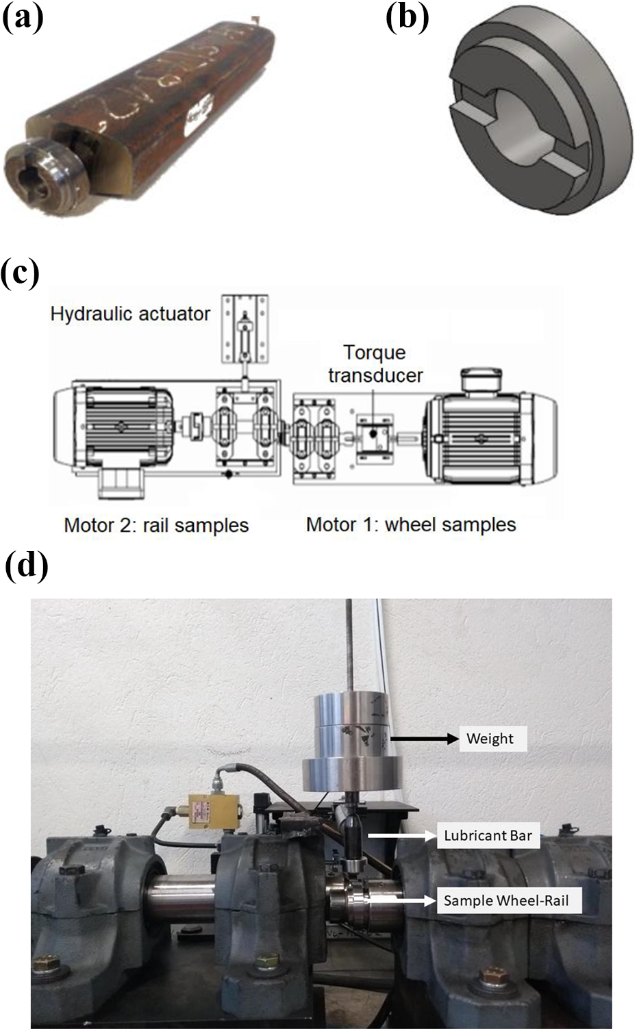
Details of the samples and the experimental setup. (a) A coupon extracted from the rail; (b) schematic of tests samples; (c) schematic of the twin-disc testing machine; and (d) closer view of the contact zone.
Wear tests were also carried out up to 8000 cycles to evaluate the effect of using the lubricant bars on the mass losses of the wheels and rail samples. The worn surfaces were inspected using SEM to identify the main wear mechanisms and eventual material transfer from the bars to the samples as well.
Results and discussion
Commercial bar characterization
Figure 2(a) shows the typical lamellae morphology of molybdenum disulfide particles dispersed in the matrix of the commercial bar. SEM backscattered electron image shows a brighter phase (solid lubricant) and the matrix (darker in the picture). Figure 2(b) shows the morphology of the molybdenum disulfide particles after the burning tests, as observed in the stereoscope. The shape of the particles is laminar with a mean lamella size of 500 µm. The bar is composed of 53 wt% of molybdenum disulfide and 47 wt% of polymer matrix. Another important feature observed during the burning tests was a smell typical of polyester and vinyl ester compounds.
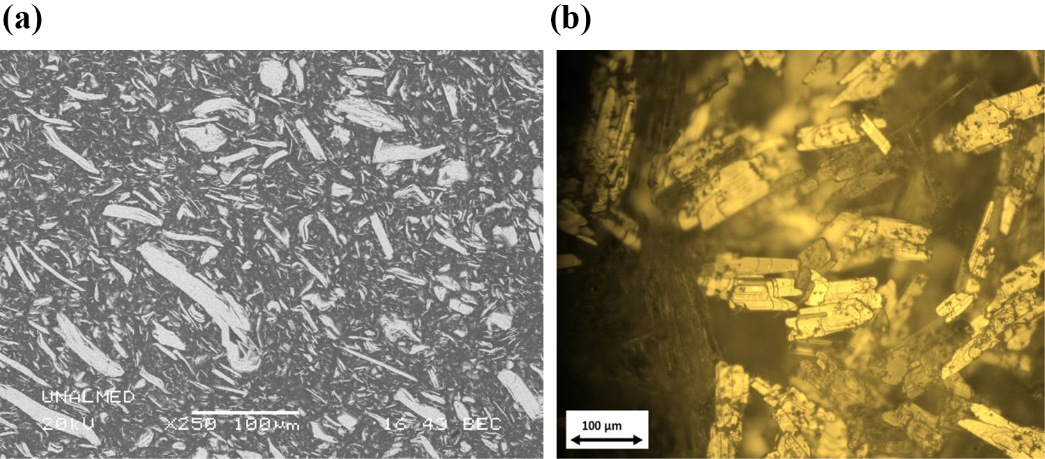
Solid lubricant in the commercial bar. (a) Cross-sectional view of a polished sample and (b) MoS2 particles only, after removal of the polymer matrix by burning at 650°C.
Figure 3 shows the Fourier-transform infrared (FTIR) spectrum of the solid bar and the bar modified with CNTs. In 2908 cm−1, there is typical signal of C–H extensions together with the bands in 1451, 1378 729 cm−1 which are typical of saturated compounds. The signals in 3024, 1600, 1492, 754, and 697 cm−1 are related to C–H extension for aromatic compounds. The matrix is a vinyl ester or polyester matrix. The manufactured bar with MoS2 had similar peaks and no additional peaks related to MoS2 were expected using infrared analysis. The only remarkable differences are related to the intensity of the peaks. The manufactured bars with CNTs (MoS2-CNTs) also showed the same peaks since the amount of CNTs (1%) is very low.
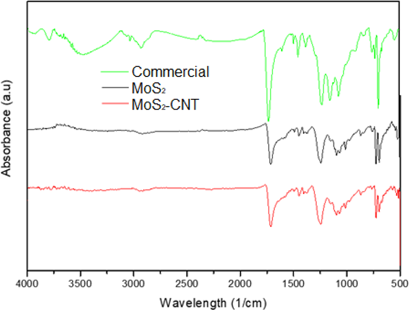
FTIR spectrum of the commercial solid bar. FTIR: Fourier-transform infrared spectroscopy.
Characterization of synthetized CNTs and CFM
Figure 4(a) shows SEM images of grown CNTs with Ni catalyst. From the image, a mixture of CNTs and catalysts residues can be observed. Figure 4(b) shows the Raman spectrum of the CNTs. The spectrum shows the three characteristic peaks related to the formation of CNTs, that is, the D band at approximately 1340 cm−1, which corresponds to the phonon mode induced by disorder (A 1g), the G band at approximately 1580 cm−1 assigned to the phonon mode allowed by Raman (E 2g), and the band G′ at approximately 2660 cm−1 assigned to the first overtone of mode D.
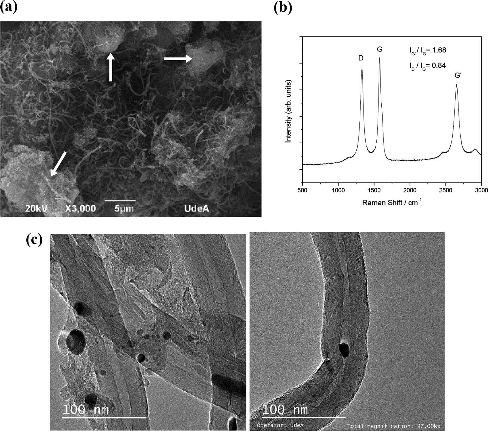
Characterization of CNTs. (a) SEM images of CNTs (arrows show the catalyst residues); (b) Raman spectra of CNTs; and (c) TEM images of CNTs. The small dark spots correspond to residual catalyst particles that were not completely removed during the purification process. CNT: carbon nanotube; SEM: scanning electron microscope; TEM: transmission electron microscope.
The D/G band intensity ratio (I D/I G) is reported to increase with increasing structural disorder. The G′/G band intensity ratio (I G′/I G) increases as the long-range order of C deposits is increased. 18 –21 From the band ratios, the I D/I G ratio value is 0.84, indicating that fewer defects are present in the sample, while the I G′/I G ratio is 1.68, indicating a greater long-range alignment. TEM image (Figure 4(c)) indicates that the obtained CNTs are of the multiple walls type (MWCNTs) since the central opening is clearly observed. The CNTs exhibit a high degree of crystallinity considering that the carbon layers are highly aligned.
Figure 5(a) and (b) shows the SEM images of the commercial molybdenum disulfide (MoS2). Heterogeneous particles from 1 µm to 50 µm can be observed. Three morphologies can be identified: flat, faceted particles, and lamellar structures. Lamellar structures were found to have an average width of 15 µm and length around to 45 μm. In Figure 5(c) and (d), images of the polished surface of the prepared bars are shown. In these images, the dark grey corresponds to the resin and the light grey to the MoS2. In both cases, a homogeneous distribution of the disulfide is evident since the bright zones are evenly distributed in the matrix. In addition, no preferential orientation of the particles can be identified. From these images, it was not possible to identify the distribution of the CNTs in the sample (Figure 5(d)).

Raw materials and developed bars. SEM: (a) general aspect of MoS2 particles, (b) detail of the MoS2 lamellae, (c) solid bar with MoS2, and (d) solid bar with MoS2 and CNTs. SEM: scanning electron microscope; CNT: carbon nanotube.
Tribological behavior
Slip curves
Figure 6 shows the slip curves for the tests carried out with the commercial, MoS2, and MoS2-CNTs samples and for the unlubricated condition as well. In all cases, the use of the FM reduces COT in more than 10% when compared to the unlubricated test. Once the COT stabilizes (for slip higher than 3%), the lower value is obtained with the MoS2-CNTs bar followed by the commercial bar, MoS2 bar, and unlubricated condition. This result is very interesting since the content of MoS2 in both the MoS2 and MoS2-CNTs bars is just 20 wt%, which is less than a half of its content in the reference (53%). It is worth noticing that for low slips the COT of the developed bars was higher than that of the commercial bar that can be associated to the differences not only in MoS2 content, but also in the resin composition and particle size distribution of MoS2. The MoS2 particles were disc-shaped in our CFM, while they were lamellar in the reference one. However, the most important feature is that the higher MoS2 content in the reference CFM could yield lower shear stress at the interface in comparison with the original CFM. This result is desirable in the field since the aim with FMs is to keep the COT within a precise range instead of reducing it to very low values.

Slip curves obtained with commercial and developed bars.
Wear tests
Figure 7 shows the mass losses of the wheel the rail samples under 1% and 5% slip. In all cases, the highest mass losses were found for the unlubricated conditions. The results of mass losses for the wheel and the rail for tests with 5% of slip are expected to be higher. In all cases, the mass loss of the rail and wheel samples are higher in the tests carried out with the commercial bar. The lowest mass loss for tests under 5% of slip was found for the bars with CNTs. The use of the lubricant bars reduces the mass loss of the samples since abrasive and adhesive wear mechanisms are hindered.
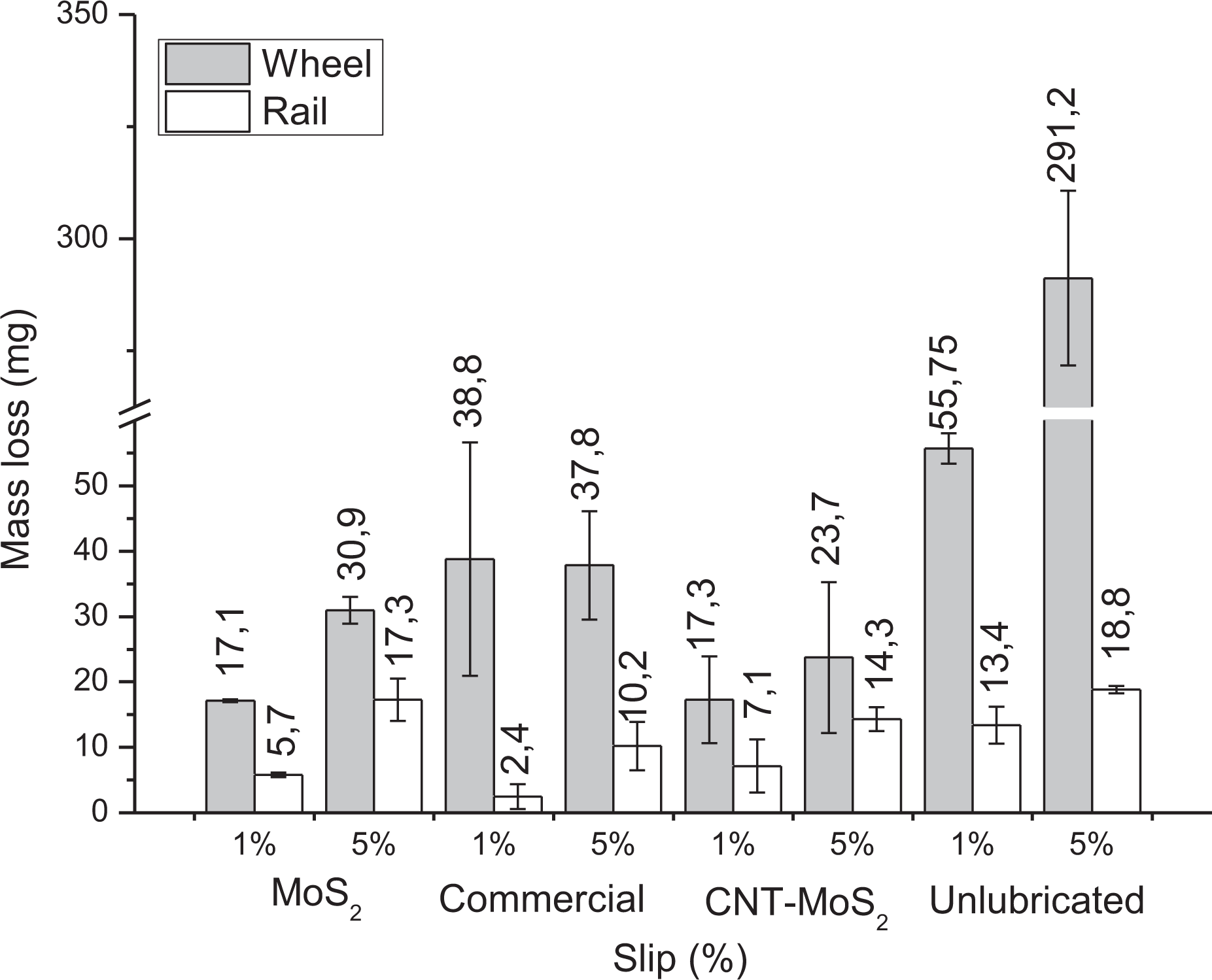
Mass losses after twin-disc tests.
Figure 8 shows the aspect of the material layers transferred to the surface of the wheel and rail samples. The proposed mechanism of layer formation is as follows: first, the rail sample causes abrasion to the solid lubricant bar and detaches material from it. The temperature at the contact helps (Figure 8(a)) softening the polymer matrix, so the transferred layer covers the irregularities at the surface of the rail sample. This reduces the COT since a material with lower shear resistance is added to the contact. Afterwards, the material moves from the rail disk to the wheel sample due to the slip imposed during the test (Figure 8(b)).

Transfer layer in samples with CNTs: (a) layer in the rail sample, 2% slip; (b) overview of transferred layer in wheel sample, 2% slip, and (c) detail of transferred layer in wheel sample, 2% slip.
Although wear improvement by adding CNT is evident from our study, the mechanisms laying behind are still fuzzy. These may involve mechanical strengthening of the composite material and the transfer film due to reduced plasticity as well as better heat dissipation. The presence of CNTs can reduce the sliding contact area under certain loading conditions. Higher flash temperature at the contact of CNTs with a countersurface may promote sintering of debris particles transferred to the countersurface and building up of more compact and well-bonded transfer film. 22,23 Furthermore, tribochemical aspects cannot be ruled out since they can lead to formation of new bonds between the CNT and the matrix or the underlying surface that also contributes to wear enhancement. Research into the mechanistic aspects of these phenomena is already underway.
Conclusions
CFMs for application at the wheel–rail interface were developed by using MoS2 and CNTs as additives in a polymer matrix. Their effect on the tribological response of wheel and rail steel samples under rolling-sliding condition was studied and compared to that of a commercial product.
The COT was reduced by more than 10% in comparison with unlubricated tests by using the original CFM functionalized with CNTs. The result was obtained using a lower solid additive content (20%) when in the commercial product (53%). The wear mass loss was also lower for the developed CFM than for the reference CFM and under unlubricated conditions.
The unlubricated testing conditions always led to higher COT values and mass losses of the steel samples since the developed bars reduced abrasive and adhesive wear.
Homogeneous lubricant transfer layers were observed on the countersurface after the tests. It is suggested that this transfer layer were responsible for maintaining the COT within a narrow range of values and for reducing the wear rate due to a boundary layer lubrication mechanism as well. The mechanisms responsible for enhancement of lubrication performance of CFM functionalized with CNT are not clear yet and will be in the focus of our further study.
Footnotes
Acknowledgment
The authors are grateful to the Metro de Medellín for providing rails and wheels for the study.
Declaration of conflicting interests
The author(s) declared no potential conflicts of interest with respect to the research, authorship, and/or publication of this article.
Funding
The authors disclosed receipt of the following financial support for the research, authorship, and/or publication of this article: This work was supported by the Spanish National Research Council (project number COOPB20363), Ministry of Science and Innovation of Spain (project number EIN2019-102889), and the Consejo Nacional de Ciencia y Tecnología—CONACYT—Mexico (grant number 740521).