
Abstract
X-Ray computed tomography (XCT) can be used to detect edge-milled carbon fibre-reinforced polymer (CFRP) defects. Significantly this method is able to show subsurface defects that cannot be captured by traditional methods such as stylus-based or more novel areal methods of surface quality measurement. While useful, this method can be prohibitive due to high equipment cost, scanning time and image resolution. XCT can often produce artefacts which falsely predict damage or obscure damage and depending on machine X-ray power often cannot resolve damage to fibre diameter which is critical when observing milled quality of the surface/subsurface. This study utilises epifluorescent (EF) optical microscopy to provide high-quality optical images as an alternative to XCT to observe through-depth damage of CFRP materials. The method of computing the novel damage criteria is presented, as well as the validation of the method which compares EF to XCT. Subsurface damage of fabric and unidirectional (UD) materials in 0°, 45°, 90° and −45° orientations to the cutting edge is observed to demonstrate typical defects. A novel metric resulting from the EF method provides a total area of damage when compared to a theoretically straight cut across the face of the edge-milled CFRP. The method shows that different subsurface damage exists for different fibre orientations to the cutting edge, highlighting the clear need for through-depth analysis of machined edges. In addition, the method is shown to be a suitable alternative to XCT with scope for further development of industrial aerospace and automotive quality control of machined CFRP parts.
Introduction
Carbon fibre-reinforced polymer (CFRP) manufacturing processes typically require an edge-trimming process to achieve the final part shape. 1,2 Edge milling is a subtractive method of achieving this net shape by removal of discrete chips of material. The cutting mechanisms involved in edge milling generate defects are specific to CFRP, 3 and as such observing the quality of the surface is of vital importance as mechanical performance of the trimmed part may be reduced. 4 Historically, a stylus has been used to measure the surface quality of the trimmed edge with a focus on surface roughness (e.g. R a). 5 More recently areal measurement methods such as focus variation have been used to gather more information from the machined surface (e.g. S a) 6 and superficial depth of damage. 7,8
While improvements have been made to characterise the surface of the machined part quality, the full extent of damage may not be captured. Scanning electron microscopy (SEM) has confirmed that matrix smearing during edge-trimming operations can occur and occurs most predominantly in fibres oriented at 90° to the cutting edge 9 . Smearing occurs across the surface of edge-trimmed samples due to high cutting temperatures generated through the abrasive nature of cutting. This temperature exceeds the glass transition temperature (T g) of the CFRP reinforcement material, where T g is the state at which the polymer becomes rubbery before its melting point. 10 The trochoidal motion of the tool during milling smears the rubbery polymer across the surface, potentially hiding defects. An example of this smearing is shown in Figure 1. This smearing may limit the results of areal methods of depth of damage recorded by authors 7,8 as the true depth of damage may be obscured and for some fibre directions (90°), the damage may be obscured entirely.

Smeared matrix observed on the trimmed surface by SEM for fibres oriented at 90° to cutting edge. SEM: scanning electron microscopy.
Recent work 11,12 has shown that XCT can be used to observe defects caused by the machining process, overcoming the obstacle of defects being hidden by smeared matrix. This method relies on the production of X-rays that penetrate the CFRP surface and are detected to produce 2D images. These images can be stitched together to provide a surface topography image of the machined material. While the work of Nguyen-Dinh et al. 11 has been completed to observe effects that are traditionally shown through focus variation methods such as depth of crater damage, the XCT method can also be used more effectively to observe machining defects which would not otherwise be seen, that is through-depth damage. However, the high costs of XCT scanning equipment, high power consumption and long scan times to achieve useful resolutions can make this method prohibitive in addition to the XCT method being unable to resolve defects to fibre diameter which potentially misses through-depth defects.
Given the need to observe defects in the CFRP material and the expense of XCT, an alternative to measuring subsurface XCT machining damage has been designed through the use of epifluorescent (EF) optical microscopy designed specifically for edge-trimming operations. The new method is then used to present a novel metric beyond current stylus and areal evaluation to quantify damage which occurs at the surface and penetrates into the depth of the trimmed material. The method is then validated against XCT of the same trimmed edges.
Proposed method
The proposed alternative to XCT requires through-depth observation of the edge-trimmed material as shown in Figure 2(a). Samples are trimmed to fit in a 30mm mounting cup using a water cooled tile saw (Erbauer) with a 1.6-mm-thick diamond disc cutter.

(a) Area of epifluorescent inspection of edge trimmed CFRP coupon and (b) CFRP sample mounted in fluorescent resin. CFRP: carbon fibre-reinforced polymer.
Following sectioning, the samples are mounted in Epo-fix which was mixed with Epo-dye (Struers, UK), an epoxy resin infused with fluorescent dye as shown in Figure 2(b). EF material has been used because of its ability to clearly show defects in damaged CFRP materials by providing extremely high contrast. 13 Cold mounting ensures that the damage caused by milling is not removed by heat which could potentially damage the CFRP material and change the specimen from its original machined condition. The mounted samples are placed in a vacuum of 0.1 N mm−2 for 5 min to ensure that the resin penetrates any cracks present in the CFRP. The samples are then cured for 24 h at room temperature. Samples were abrasively polished to remove the face of the material which may have been damaged by the Erbauer tile saw and finally polished to provide a smooth surface for optical observation using the polishing regime noted in Ashworth et al. 14
An X-Cite ultraviolet light box (Excelitas, Best Scientific, UK), a 5-MP digital camera (Pax-it, Best Scientific, UK) and microscope at 2× magnification were used to capture the EF sample, an example is shown in Figure 3(a).
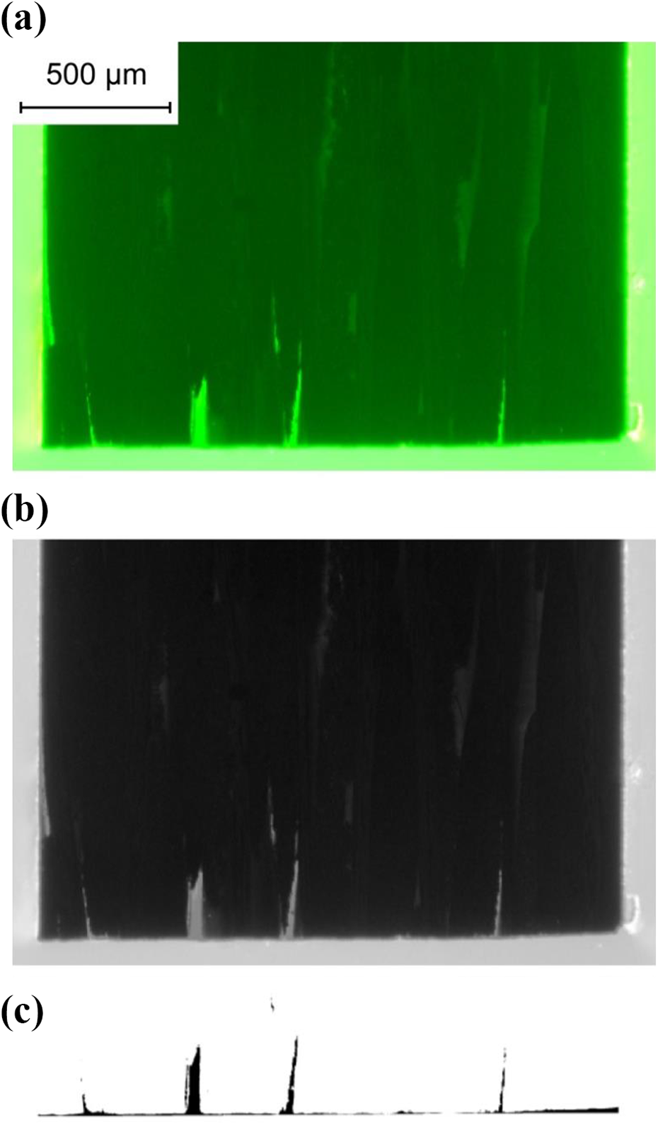
(a) Epifluorescent image showing through-depth damage, (b) Matlab processed greyscale image and (c) Matlab/Otsu processed binary image showing damage.
The EF material has allowed a high contrast between the damaged and the un-damaged CFRP. To determine the amount of damage shown in Figure 3, the digital image can be subject to pixel thresholding. Thresholding of colour images is possible, however the image was changed to a greyscale for simplicity of Matlab (Mathworks). A Matlab script changes the colour image to a greyscale image as shown in Figure 3(b).
A further Matlab subroutine allows the user to define a straight edge which can be drawn across the edge of the image to represent a theoretical straight cutting line. Deviations from this cutting line are highlighted by the EF mounting material and thus represent damage. Automated Otsu thresholding 15 is then used within Matlab to yield a binary image of damaged areas as seen in Figure 3(c). Further Matlab calculations provide a novel damage metric which presents a pixel count/actual area (when used with a calibrated microscope) of machining induced damage in addition to a visual representation of damage.
Automated thresholding is chosen to remove potential user errors when selecting the threshold between bright and dark or damaged and non-damaged areas. While there is a clear difference by visual observation of the image, a histogram of the image pixels shows some pixels are between bright and dark areas, so a consistent, non-biased approach to threshold selection can be taken using the Otsu method. 15
Verification of method
To ensure that the proposed method observes defects due to machining and not due to the preparation of samples, XCT scans of CFRP at differing fibre orientations to the cutting edge have been observed. In addition to observing defects of UD materials at fibre orientations of 0°, 90°, +45° and −45° to the cutting edge, an observation of a fabric material has been completed. This array of fibre orientations to the cutting edge will not only allow verification of the EF method against XCT but also showcase typical defects that occur due to the edge-trimming process.
UD laminates were manufactured from 12 layers of MTM46-36%–12KHTS40-250-300 (Solvay, UK), a high-performance toughened epoxy resin prepreg to create a specimen of 3 mm thickness. The laminate was cured using an autoclave regime presented in Table 1.
MTM46 UD coupon curing regime.

UD: unidirectional.
The [((0,90)/(+45,−45))3/(0,90)]s fabric material was manufactured using a resin transfer mould (RTM) process described in Ashworth et al. 9 to create a 3-mm-thick cured laminate. This method used T300, 2 × 2 twill, 200 gsm, TC3091000 fibres (Sigmatex, UK) injected with a custom resin system made of DGEBF PY306 epoxy (Huntsman, UK) and TETA hardener (Sigma Aldrich, UK) at a stoichiometric mixing ratio of 100:15 epoxy:resin. The mixed resin was injected at pressures given in Table 2. Material was then cured according to Table 3, where segment 1 cured the CFRP panel in the RTM tool and segment 2 was the CFRP panel only.
T300 Fabric coupon RTM regime.

RTM: resin transfer mould.
T300 Fabric coupon curing regime.

All materials have been edge trimmed using a full slot up/conventional milling procedure with a diamond coated burr style tool (OSG Corporation, UK). Nguyen-Dinh et al. 12 show that increased radial depth of cut increases the surface damage and depth of damage, and the use of full slotting is likely to provide high levels of damage. The DIA-BNC tool is a fine nicked router designed for CFRP trimming with the nick and flute form designed to eliminate uncut fibres and delamination. The DIA-BNC tool has a double helix, each at 15° with a relief and rake angle of 18° and 8°, respectively. The machining parameters used for all trimming operations are given in Table 4. The same tool was used for all trials.
Machining parameters.
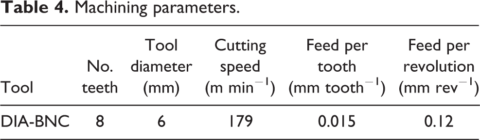
Fabric and UD material was machined using a Cincinnati CFV (MAG) and 1060HS (XYZ) three-axis milling machine, respectively. Samples were rigidly clamped to custom tooling blocks which allowed an unsupported edge with an overhang of 0.5 mm to allow the milling tool to engage with CFRP material with a single pass. Machining was completed without coolant and a extraction system (001 NT 35/1 Tact Te, Karcher) was used to capture harmful CFRP dust 12,16 at source.
UD samples at +45°, 90° and −45° orientation contained uncut burrs which is typical of the machining process. 17 These burrs were removed prior to XCT as the fibres caused artefacts in test scans due to image lag and ghosting. 18
XCT was completed using “Skyscan 1172 (Bruker)” equipment with the following settings: voltage: 40 kV; current: 149 µA; filter: none; the low power nature of the machine necessitates the use of all emitted X-rays; and exposure level = 295.
Post-processing of the images was completed using “CTvox v3.0 (Bruker)”, a free to download software to produce images that are shown in Figure 4. The 3D image is made of up to 1879 single planar slice .tiff images that can be used for direct comparison to EF images such as that shown in Figure 3(a). As such, each image is separated by approximately 8.75 µm. Comparison of individual XCT .tiff images will be made with a single EF image to observe whether the machined edge damage is replicated. It is noted that the final image resolution, artefacts and approximate distance between images may cause errors in exact visual comparison to EF images.

3D XCT scan of UD fibres oriented at 0° to the cutting edge made from 1879 planar .tiff images to allow comparison to EF method. XCT: X-ray computed tomography; UD: unidirectional.
Results
Figure 5 shows the binary images created through the use of the novel damage metric for the various fibre orientations used within this study. By applying the thresholding method described in the second section, the total amount of damage compared to the theoretically straight cut can be calculated. The amount of damage is shown in Figure 6, where error bars represent repeatability error of the novel process.

Binary images denoting damage obtained through novel metric calculations.

Novel metric damage results for differing fibre orientations to the cutting edge.
It can be seen that machining 90° fibres forms the greatest level of damage. Figure 5 shows large-scale damage along the length of the fibres/fibre–matrix interface. The damage occurring during machining of 90° is described by Wang et al., 19 with the cutting force causing shear of the fibres and the force also causing a mode I type opening along the fibre–matrix interface. Various authors 20,21 described the cutting process of this fibre orientation as a type I delamination where the failure mode propagates into the trimmed edge by some unspecified distance. Fibres at +45° to the cutting edge exhibit the least amount of damage when using the novel metric even compared to 0° fibres which typically exhibit the least amount of surface damage according to the literature. 3,21 However, the subsurface damage of the 0° fibre specimen may have occurred due to a void in the laminate which has been exposed by the machining process. Fibres at −45° typically exhibit the most amount of surface damage due to the fracture below the cutting plane 3,21 ; however, results show a low amount of subsurface damage compared to 0° and +45° samples. It is noted that the measurements of damage provided by Sheikh-Ahmad 3 and Wang et al. 19 refer to surface damage and not subsurface damage. This may account for the differences observed and highlight the importance of measuring subsurface defects which would otherwise not be seen. Importantly, Sheikh-Ahmad et al. 21 have noted the presence of subsurface cracks in 90° and −45° plies which can now be explored further and presented using the EF method for the first time. The fabric material shows the second highest level of subsurface damage and when compared to 0°, +45° and −45° fibres, the trimmed edge is not as straight compared to theoretical. This may be a difference due to machine stability which is known to change the properties of the machined surface, 9 or it may be due to the individual ply orientations being supported at either side by differing fibre orientations. This may change the chip formation method and subsequent subsurface/surface damage. It is also noted that the fabric material uses 3 k fibre tows, while the UD material is made from 12 k fibre tows which may change the fracture mode causing differing levels of damage.
Figure 5 shows that subsurface defects have occurred for fabric, 0° and 90° fibres which would not have been captured with methods such as focus variation. While images show subsurface damage, it is noted that a larger population of sectioned material is required to draw full conclusions of cutting modes of differing fibre orientations.
Figure 7 shows the verification results when the EF method is compared to XCT images. While the resolution of the XCT is limited by relatively high distance between scan sections compared to fibre diameter, artefacts and ghosting, all of which do not allow individual fibres to be imaged, it can be seen that major areas of damage on the machined edge seen through XCT is replicated in the EF images. Importantly, the EF images do not exhibit further damage from the processing method. The machined edge shown for the −45° XCT sample does not match the EF closely which may be due to the distance between individual images taken by the XCT equipment; however, the contrast available shows some light greyscale areas which can be interpreted to allow a match with the EF image.

Verification of epifluorescent method by comparison with single-planar slice XCT. XCT: X-ray computed tomography.
Visible transverse cracks for 90° fibres can be seen in the EF image in Figure 7 and are observed to a less visible extent in the XCT image. This is due to power limitations in the XCT equipment which does not allow resolution to individual fibre level in addition to the production of artefacts which mask areas of no material.
Low damage has been exhibited for fibres at +45° to the cutting edge due to the clean shearing mechanism of the fibres. Therefore, it is difficult to verify the EF method with the resolution limit of the XCT equipment used. However, Figure 8 shows validation through inspection of a deeper surface which shows that voids are seen alongside a small amount of edge damage which can be seen in the XCT image.

Further verification of damage to +45° fibres.
The observation of voids is also a useful attribute to the proposed novel method as defects such as this, in addition to machining damage, are likely to cause altered mechanical performance. 22 While further information is required to know whether the machining process has followed a void path, such as pre-machining XCT of the coupon, the final defects at the machined edge can be clearly seen and would contribute to a change in mechanical performance.
Conclusions
This investigation assessed the subsurface, machining induced damage of fabric and UD, edge-milled CFRP by using an EF method and a novel damage criteria. Further to this, the EF method was verified by XCT. Based on the experimental results obtained, the following conclusions can be drawn: The bulk damage due to the cutting edge is the same between XCT and EF images. This suggests that EF is a suitable alternative to the XCT method. The EF method presented is able to identify areas of subsurface damage which would not be visible to surface analysis techniques such as stylus or focus variation microscopy. Further to this, the method is able to more accurately measure subsurface damage than the XCT method. This is vitally important as the defect type and size have been directly linked to mechanical performance.
9,23
–26
By using the EF method, a novel metric which accounts for machining induced damage of CFRP edge trimming has been generated. The novel metric is able to provide a value for total damage area compared to a theoretically straight cut. Fibres at different orientations to the cutting edge exhibit different subsurface damage levels. The subsurface damage observed by the limited sample size shows that subsurface damage may differ to the typical surface damage mechanisms shown in the current literature.
Footnotes
Authors’ note
The findings within this paper were previously presented at the 22nd International Conference on Composite Materials 2019.
Acknowledgements
The authors would like to acknowledge the EPSRC Industrial Doctorate Centre in Machining Science (EP/L016257/1) for the funding of this work and to the OSG Corporation for the supply of tools. Thanks, are also extended to the Factory of the Future at the Advanced Manufacturing Research Centre with Boeing for machining equipment and operators and to Caroline Fry of the skeletAL group, The Department of Oncology and Metabolism, The University of Sheffield for use of XCT equipment.
Declaration of conflicting interests
The author(s) declared no potential conflicts of interest with respect to the research, authorship, and/or publication of this article.
Funding
The author(s) disclosed receipt of the following financial support for the research, authorship, and/or publication of this article: This work was funded by EPRSC Industrial Doctorate Centre in Machining Science (EP/L016257/1).