
Abstract
Elliptical vibration-assisted cutting (EVC) is an efficient cutting process in the fabrication of microtextures. In this paper, a novel locus control method for EVC is proposed to fabricate intricate surface textures. First, the mechanism of the EVC microtexturing process is analyzed. Then the detailed ideas and mapping process of the locus control method of EVC according to the model of microtexture are investigated. To realize the mapping process of the locus control, the relationship between the elliptical vibration locus and the discrete points of the microtexturing model is established, while the generation algorithm of excitation inputs for the actual elliptical vibration exciter is developed. A series of EVC microtexturing turning experiments are performed while microtexturing simulation experiments are also conducted. The test results between microtexturing turning and simulation experiments show that the proposed locus control method is satisfactory and can be used to fabricate differently shaped microtextures.
Introduction
The demand for functional surfaces has recently been increasing in many industries controlled by micro and nanoscale surface structures that control the surface’s functions for industrial uses such as aerospace, tribology, and other fields of engineering.1–4 Different types of textured surfaces can perform different functions. These different types of textured surfaces can be fabricated by various processes,5–11 such as laser scribing, micro-end milling, and atomic force microscope scribing. The lithography technique can produce accurate textures; however, the high cost limits its broad application in surface texturing. 12 In order to generate surface textures, micromachining is a promising approach, considering its high form accuracy and flexibility.13, 14 Micromachining by adding elliptical vibration-assisted cutting (EVC) will provide a potential process for precision machining of microstructured surfaces. EVC brings a lot of machining advantages, such as suppression of burrs, reduction of tool wear, and enhanced material removal rate,15–17 by adding small amplitude, high-frequency tool displacement to the cutting motion of the tool. Suzuki et al. 18 described a new ultra-precision sculpturing method at the micro/nanoscale by using variations of the elliptical vibration locus and fabricating microtextures on hardened steel surfaces. The amplitude control sculpturing method is proposed by Zhang et al.19, 20 in elliptical vibration cutting, considering locus compensation. Guo et al. 21 focused on the fast generation of dimples on cylindrical surfaces and obtained the micro-channeling topography by the EVC method. Its generation process depended on different machining modes by elliptical vibration texturing, and Wang et al. 22 further explored modulated ultrasonic elliptical vibration cutting for ductile-regime texturing of brittle materials with two-dimensional (2D) combined resonant and non-resonant vibrations. Gandhi et al. 23 investigated the ability to prescribe microscale textures of controlled size and morphology by controlling underlying process parameters. Xu et al. 24 described a novel rotary ultrasonic texturing method to generate period microtexture and nano-texture on flat surfaces by using a one-point diamond and obtained textures with submicrometer dimensions.
However, these proposed fabrication methods face two problems that have not been solved yet. First, locus control of the EVC textures is limited to the specified EVC mechanism with a fixed frequency and amplitude under the resonant mode of operation. Second, for the most developed mechanism, the corresponding locus control of the EVC textures is still difficult to fabricate micro/nano texturing of arbitrary geometric characteristics with high efficiency, which is required in actual industry applications, for example, aero-engine blade surfaces for reduced fluid resistance or friction.
Based on the above-mentioned problems, the establishment of a mapping relation between arbitrary microtexturing characteristics and the elliptical vibration locus in the EVC process is key to extending the capabilities of the existing locus control method and controlling the elliptical vibration locus based on an arbitrary textured surface. Studies have shown that dimples can be generated on cylindrical surfaces by ultrasonic elliptical vibration cutting25, 26 and that microtextures can be fabricated using the proposed ultrasonic elliptical vibration cutting mechanism. 27 In this paper, a novel locus control method of elliptical vibration is proposed to fabricate intricate surface textures based on a microtexturing model. The elliptical vibration locus during the cutting process is generated by a 2D resonant ultrasonic vibrator, and 2D vibrations are used in this proposed locus control method. A mapping process of locus control is investigated, which is used to set up the mapping relationship between the microtexturing model and the excitation inputs. Actually, the proposed locus control method can also be utilized in other 2D or 3D resonant ultrasonic vibrators.
The structure of the paper is as follows. First, the elliptical vibThe structure of the paper is as follows. First, the elliptical vibration-assisted microtexturing process is analyzed in section the EVC microtexturing process. Section locus control method of elliptical vibration is about the locus control method of elliptical vibration including the idea of locus control of elliptical vibration, the mapping process of locus control, the generation algorithm of the elliptical vibration locus based on the microtexturing model, a generation algorithm of excitation inputs for the elliptical vibration locus, the realization of locus control software for elliptical vibration. Verification of the locus control method is given in section experimental verification and discussion including is about the experimental setup, the machining experiment and simulation of microtexturing generation, the detailed verification, and the comparison between the simulation data and experimental results. Conclusions are given in last section.
The EVC microtexturing process
Principles of the EVC
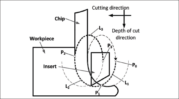
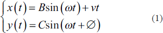
In microtexturing, an elliptical locus is generated by the 2D vibration of the tooltip and the feed action of the workpiece, as shown in Figure 1, with a single vibration cycle following the path
Principles of the elliptical vibration-assisted cutting process.
Generation of the elliptical vibration-assisted microtexture
The EVC can be used to generate microtextures. The generation process of microtextures using the EVC is shown in Figure 2. A locus of ultrasonic elliptical vibration is obtained by the excitation of the vibrator, and a series of surfaces are formed by the generated elliptical vibration locus. These formed surfaces are swept along different base surfaces, such as the cylindrical surface or blade surface in Figure 2, and intersected with different base surfaces. The microtextures will be generated on the base surface.
Generation of microtextures on different base surfaces using elliptical vibration-assisted cutting.
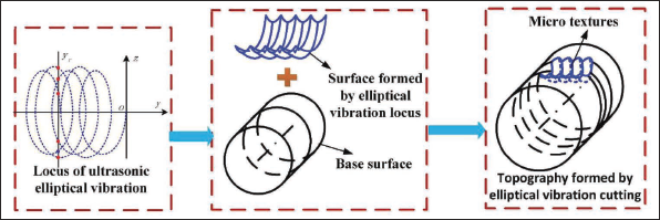
As can be seen, the generated microtexture on the base surface with the EVC depends on the elliptical vibration trajectory (frequency and amplitude), the cutting speed, feed rate, and tool geometry. The necessary variation of the EVC locus can be obtained by modifying the amplitude and phase difference of the excitation inputs.
The elliptical vibration generator
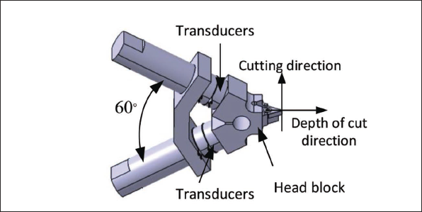
The elliptical vibration cutting apparatus used in this paper is composed of two bolt-clamped Langevin transducers. The model of the EVC studied in this paper is shown in Figure 3. In the present apparatus, the angle between the two transducers is held at 60 degrees. The dimensions of the device are approximately 100 mm × 100 mm × 40 mm. The two end masses of the transducers provide the necessary preloads for the PZT rings. The length of the end masses is optimized to adjust the natural frequencies of the device.
Model of the elliptical vibration-assisted cutting structure.
The tool’s position relative to the workpiece in EVC is given by:
While its velocity, again relative to the workpiece, is:
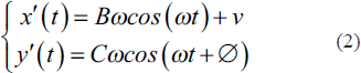
where
The EVC can be modeled as a series of overlapping ellipses. This is illustrated in Figure 1. The amount of overlap between the elliptical tool paths is a result of the distance indexed between cutting cycles. This index distance is defined as:
where
Locus control method of elliptical vibration
The idea of locus control
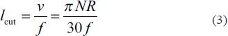
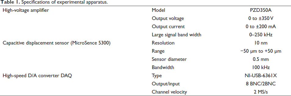
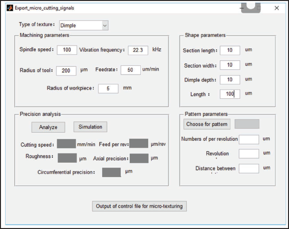
Based on the above analysis of the elliptical vibration-assisted microtexturing process, the output locus of the elliptical vibrations should be suitably adjusted according to the actual requirements for obtaining intricately shaped microtextures. That is to say, the output locus of elliptical vibration will influence the generation of microtextures, while the output locus of elliptical vibration is up to the amplitudes, frequencies, and phase differences of excitation inputs. For the designed 2D elliptical vibration exciter in the paper, an actual elliptical vibrator is manufactured, as shown in Figure 4a, and an experimental test system for the vibrator is established, as shown in Figure 4b. The resonant frequency of the developed elliptical vibrator is 22.3 kHz, and the calibrated amplitudes in the depth of the cut direction and in the cutting direction are shown in Figure 5a.The developed elliptical vibrator is excited by the sinusoidal excitation signals. The detailed specification of the experimental apparatus is given in Table 1.
The schematic of elliptical vibrator and test system. (a) Elliptical vibrator and (b) test system.
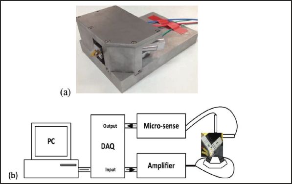
The influence of excitation inputs on elliptical vibration. (a) The influence of excitation inputs on the amplitudes of elliptical vibration. (b) The influence of excitation inputs on the orientation of elliptical vibration.
Specifications of experimental apparatus.
The actual test results about amplitude, the phase difference of input excitations, excitation input voltage, and the orientation of the generated elliptical vibration locus is shown in Figure 5.
In Figure 5, the influences of the amplitude of excitation inputs on the amplitudes of elliptical vibration in cutting direction and depth of cut direction are shown in Figure 5a. It can be seen from Figure 5a that the amplitudes of the elliptical vibration locus in the depth of cut direction and cutting direction increase with the increase of the amplitude of the excitation inputs. The orientation of the elliptical vibration locus compared to the cutting direction is also influenced by the amplitudes, the frequency, and the phase difference of excitation inputs, and Figure 5b shows the influence of the phase difference of excitation inputs on the orientation of elliptical vibration locus. From Figure 5b, it can be concluded that the phase difference of excitation inputs will change the orientation of the generated elliptical vibration locus. Thus, it can be seen from Figure 5 that both the amplitude and phase difference of excitation inputs have an influence on the elliptical vibration locus and the elliptical vibration locus can be controlled by changing the amplitude and phase difference of excitation inputs based on the actual requirements of the microtexturing generation.
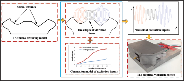
The idea of locus control is shown in Figure 6. In Figure 6, the amplitudes and phase differences of sine wave signal 1 and sine wave signal 2 are regulated to generate the suitable sine wave signals based on a microtexturing model to be machined. Then the regulated sine wave signals are exerted on the actual elliptical vibration exciter. Thus, the suitable elliptical vibration locus is generated based on the actual requirements and the intricately shaped microtextures can be obtained by the generated elliptical vibration locus.
The schematic of locus control.
The mapping process of locus control
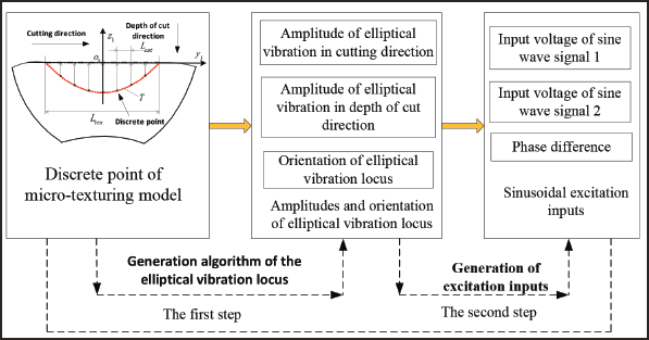
Based on the above idea, a new locus control method of elliptical vibration is proposed to generate the elliptical vibration locus and excitation inputs in the paper. The locus control method consists of two steps. The first step is to prepare the suitable elliptical vibration locus for the following generation of microtextures. In this step, the amplitude and phase difference of the suitable elliptical vibration are obtained based on a microtexturing model. The key problem in this step is to establish the mapping relationship between the microtexturing model and amplitudes and phase difference of the elliptical vibration locus for generating the elliptical vibration locus. The main work in this step is to generate the elliptical vibration locus based on the microtexturing model, and this step is named the generation of the elliptical vibration locus based on the microtexturing model. The second step is to construct the relationship between the elliptical vibration locus and excitation inputs for generating suitable excitation inputs based on the actual elliptical vibration exciter. In this step, the generated excitation inputs, that is, sine wave signals, are amplified by a voltage amplifier, and the amplified sinusoidal excitations are exerted on the actual elliptical vibration exciter to generate the required elliptical vibration locus. Thus, the elliptical vibration locus with different amplitudes and orientations is obtained based on the established corresponding relationship. This step is called the generation of excitation inputs.
By using the above two steps, a suitable elliptical vibration locus is generated according to the microtexturing model, and the regulated excitation inputs, which is corresponding to the suitable elliptical vibration locus, are output to the actual EVC device. Figure 7 shows the mapping process of locus control. Thus, the intricately shaped microtextures can be obtained on the actual elliptical vibration exciter by using the control of the elliptical vibration locus.
The mapping process of elliptical vibration locus.
Generation algorithm of the EVC locus
In the mapping process of the elliptical vibration locus, it is important to generate the EVC locus based on a geometry model of microtexture to establish the relationship between the amplitudes and orientations of the elliptical vibration and the microtexturing model. Thus, geometry data from the microtexturing model can be used to generate the corresponding amplitudes and orientations of elliptical vibration, and the generated amplitudes and orientations of elliptical vibration are transformed into the corresponding sine wave signals, which are exerted on the actual elliptical vibration exciter for obtaining the output EVC locus. Elliptical vibration loci with different amplitudes and orientations will generate different topography characteristics in microtextures. Based on the above idea, the generation algorithm for EVC loci based on the geometry model of microtexture is proposed in this paper. The detailed steps of the proposed algorithm are as follows:
Step 1: Selection of machining parameters for microtexturing and the parameters of the cutter, and calibration of the resonant frequency of the actual elliptical vibration exciter. Step 2: Discreteness of the microtexturing model.
The microtexturing model is discretized into a series of points along. The discrete precision is up to the frequency of the EVC device and feed per revolution. In order to generate accurate microtextures, the minimum discrete precision 
where,
Step 3: Determination of the elliptical vibration locus for discrete points.
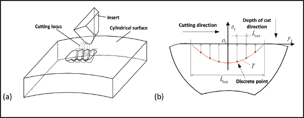
In order to obtain the actual microtextures within accuracy, each discrete point for microtexturing on a cylindrical surface should be taken as the contact point of an elliptical vibration locus with the ideal topography of microtextures, and these contact points should suffice to ensure the machining accuracy of microtextures. Thus, the corresponding elliptical vibration amplitude for an arbitrary discrete point on a dimple can be calculated. The discrete points on the dimple are transformed into the control points of the elliptical vibration locus, which will be used to generate the dimple. The calculation schematic for each discrete point is shown in Figure 8b. In Figure 8b, a local coordinate system
The discrete microtexturing in the elliptical vibration-assisted cutting process. (a) The generation processes of microtexturing. (b) The discrete along the circumferential direction.
Generation of excitation inputs
After obtaining the EVC locus, the suitable sinusoidal excitation inputs exerting the actual elliptical vibration exciter need to be related to the elliptical vibration locus. The generation process of excitation inputs can be described as:
Step 1: The analysis of linear ranges.
Some test data about the amplitudes and orientations of the elliptical vibration locus and the voltages of sinusoidal excitation signals are illustrated in Figure 5. From Figure 5, it can be seen that there are some linear ranges between the excitation inputs and the elliptical vibration locus with amplitudes and orientations. It can be seen from Figure 5a that the linear ranges of the amplitudes in the cutting and depth of cut directions are approximately from 2 to 10 µm, and the linear ranges of the orientation of elliptical vibration are nearly from 0° to 70° from Figure 5b. These linear ranges for amplitudes and orientation nearly include the whole amplitude and orientation variance based on the actual elliptical vibrator. Thus, based on these linear ranges of amplitudes and the orientation of the elliptical vibration locus with excitation inputs, the suitable excitation inputs to the actual vibration exciter can be obtained according to the generated elliptical vibration locus.
The above analyzed linear ranges will be used to establish the corresponding relationship between excitation inputs with voltage amplitudes and phase difference and the elliptical vibration locus with amplitudes and orientation, which is the generation model of excitation inputs, will be established on these linear ranges. The input variables of the established model include the amplitudes and phase differences of two sinusoidal excitation inputs, and the outputs of the established model are the amplitude of the elliptical locus in the cutting direction, the amplitude of the elliptical locus in the depth of the cut direction, and the orientation of the elliptical locus, which is denoted by the angle of the major axis of the elliptical locus compared to the cutting direction.
Step 2: The establishment of a generation model of excitation inputs.
Based on the linear variance ranges of the amplitude of the elliptical locus in the cutting direction and the amplitude of the elliptical locus in the depth of cut direction shown in Figure 5a, the input voltages of sinusoidal excitation signals are both in the range of 0.6 V–2.1 V compared to the variances of amplitudes from 2 to 10 µm when taking the same phase difference of 90°. Thus, the generation model of excitation inputs with the amplitudes of elliptical vibration in the cutting direction and depth of cut direction can be obtained based on the actual measured data as follows:
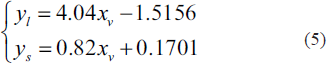
where
It can be seen from Figure 5b that there exists a linear relationship between the amplitude of sine wave signals and the orientation of the generated elliptical vibration in the range of 0.60 V–2.1 V of the input voltage of sinusoidal excitation signals when the phase difference between the two input sine wave signals changes. Thus, the generation model of excitation inputs with the orientation of elliptical vibration on these linear ranges can be calculated as:
Step 3: The generation of excitation amplitudes.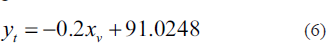
Based on the relationship between the amplitude in depth of cut and the excitation amplitude of sine wave signals of an established elliptical vibrator, such as Equation (5), the amplitude of the sinusoidal excitation inputs can be expressed by the required elliptical vibration locus with amplitudes as:

Thus, the excitation inputs of the elliptical vibration locus for each discrete point are determined.
Step 4: Output of locus control files for microtexturing.
In order to realize the control of the actual vibration exciter, the excitation inputs of the elliptical vibration locus for each discrete point on microtexturing are saved as a locus control file. The locus control file is output to the actual exciter for the actual EVC microtexturing. Thus, the required microtextures can be obtained.
Realization of locus control software of the elliptical vibration
Locus control software for elliptical vibration (LocusEVC) is realized based on MATLAB software by using Windows information and communication mechanisms according to the proposed locus control method of the EVC, including the generation algorithm of the elliptical vibration locus based on the microtexturing and the generation algorithm of excitation inputs for the elliptical vibration locus based on the actual elliptical vibration exciter. The interface of LocusEVC software is shown in Figure 9.
The schematic of the interface of LocusEVC.
Experimental verification and discussion
Experimental setup
Ultrasonic EVC microtexturing experiments are carried out on a DMG ULTRASONIC 20 linear machine tool. The developed ultrasonic vibration apparatus is shown in Figure 10a and installed in the DMG ULTRASONIC 20 linear machine tool. The workpiece is loaded into the spindle along the z-axis. The spindle provides the primary motion in the turning operation. The sinusoidal excitation voltages with varying magnitudes and phases were generated by a dual-channel function generator and amplifier.
Schematic of ultrasonic elliptical vibration-assisted cutting machining system. (a) Ultrasonic elliptical vibration-assisted cutting machining system and (b) machined microtextures.
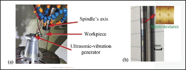
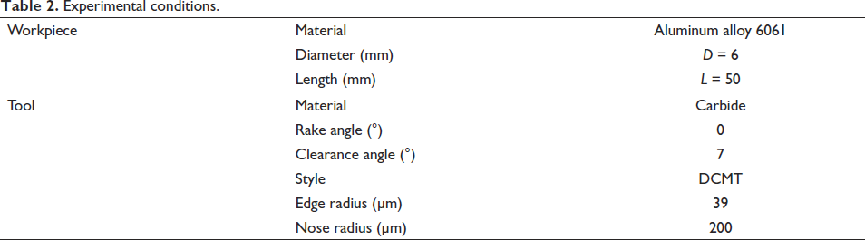
The cutting tools used were commercial tungsten carbide inserts with a nose radius of 200 µm and an edge radius of 39 µm. The cutting-edge sharpness was very important for micromachining because it caused errors in the profile size and shape. Thus, edge radius and nose radius were also important indexes for fabricating microtextures. The workpiece material used in the elliptical vibration-assisted microtexturing turning was aluminum alloy 6061. The experimental conditions used for the ultrasonic elliptical vibration-assisted microtexturing turning process are presented in Table 2. Each experiment in Table 2 is used to machine microtexture under ultrasonic EVC conditions. Some typical machined workpieces with microtextures are shown in Figure 10b.
Experimental conditions.
Machining experiment and simulation of microtexturing
Dimples on a cylindrical surface are selected to conduct machining experiments. The dimples on the cylindrical surface, which are selected in machining experiments, are along the peripheral direction of the cylinder. The diameter of the cylinder is 6 mm. The dimple is divided into a series of points along the axial and circumferential directions of the cylinder. The discrete precisions of the axial direction and circumferential direction of the cylinder are up to the resonant frequency of the elliptical vibrator and feed per revolution. Each discrete point is calculated according to the detailed calculation process in generation algorithm of the EVC locus section. A locus control file for the elliptical vibration is generated based on the proposed locus control method for elliptical vibration.
The generated locus control file is fed to the EVC microtexturing system, while the suitable sinusoidal excitation inputs are output to the actual elliptical vibration exciter. The different locus control files are generated for differently shaped microtextures. Thus, the sinusoidal excitation inputs are different from the actual elliptical vibration exciter for differently shaped microtextures. The different EVC loci can be obtained by exerting the different sinusoidal excitation signals on the actual elliptical vibration exciter. So, the differently shaped microtextures can be machined based on the obtained EVC locus. At the same time, the EVC locus from the locus control file, which is from the microtexturing model, is used to simulate the generation of microtextures on cylindrical surfaces in order to compare the effectiveness of EVC locus control.
Verification of locus control of the elliptical vibration
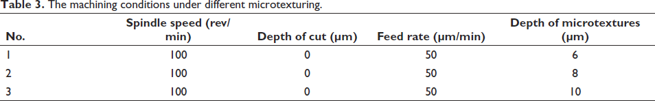
The ultrasonic elliptical vibration-assisted microtexturing turning experiments were conducted for three cases in Table 3. The locus control files are generated by using LocusEVC software for the machining parameters of Nos. 1–3 in Table 2, and three groups of dimples on the cylindrical surface are obtained by using the generated locus control file.
The machining conditions under different microtexturing.
Under all experimental conditions listed above, three groups of surface topography for the generated microtexture were measured using the three-dimensional (3D) white light interferometer UP Dule. The resolution of the 3D white light interferometer UP Dule is 0.2 µm. The actual machining surface topographies with Table 3 parameters Nos. 1–3 are shown as Figures 11a, 12a, and 13a, respectively. The simulated surface topographies of generated dimples on cylindrical surfaces with Table 3 parameters Nos. 1–3 are shown as Figures 11b, 12b, and 13b, respectively.
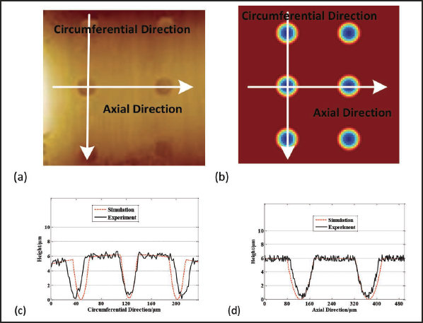
The comparison of surface topography with a depth of dimple 6 μm. (a) Experimental topography, (b) simulation topography, (c) comparison in the circumferential direction, and (d) comparison in the axial direction.
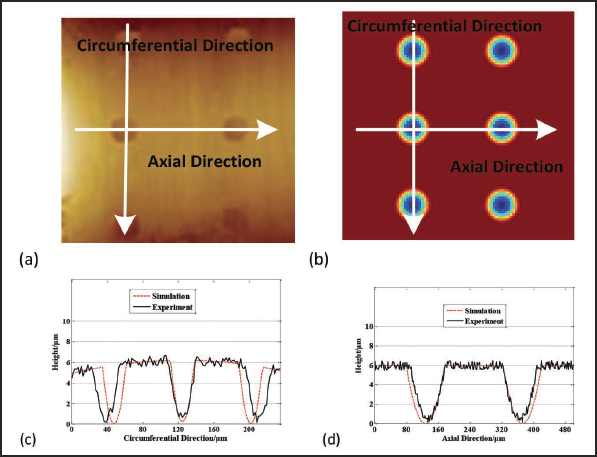
The comparison of surface topography with a depth of dimple 8 μm. (a) Experimental topography, (b) simulation topography, (c) comparison in the circumferential direction, and (d) comparison in the axial direction
The comparison of surface topography with a depth of dimple 10 μm, (a) Experimental topography, (b) simulation topography, (c) comparison in the circumferential direction, and (d) comparison in the axial direction.
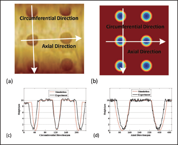
For displaying surface topography more clearly, the enlarged images of dimples in circumferential and axial directions are also shown in Figures 11–13. Figures 11c, 12c, and 13c give the comparison of dimple height between simulation results and actual experiment results in the circumferential direction of the cylinder. Figures 11d, 12d, and 13d present the comparison of dimple height between simulation results and actual experiment results in the axial direction of the cylinder.
Results analysis and discussion
Figures 11a, 12a, and 13a are actual surface topographies of dimples under different depths of cut, while Figures 11b, 12b, and 13b are simulation surface topographies of dimples under different depths of cut. In Figures 11a, 12a, and 13a, circumferential direction refers to the horizontal trajectory paralleling the feed direction, and axial direction refers to the trajectory perpendicular to the feed direction. It can be observed from the comparison between the actual surface topography of Figures 11a, 12a, and 13a and the simulations for surface topography of Figures 11b, 12b, and 13b that the variant trends of surface topography in experiments are similar to those of surface topography in simulations.
The depth of dimples along the circumferential direction in both simulations and experiments is enlarged in Figures 11c, 12c, and 13c. It can be seen fromFigures 11c, 12c, and 13c that the depths of dimples along the circumferential direction for actual experiments have the same height as that of simulation data. The enlarged images of one stepover in Figures 11c, 12c, and 13c show that the dimples from the experimental results and simulation data along the circumferential direction have a similar wave, and the section shapes of adjacent dimples for actual experiments are like those of simulation. The depth of dimples along the axial direction in both simulations and experiments is enlarged in Figures 11d, 12d, and 13d. The enlarged images of one vibration cycle in Figures 11d, 12d, and 13d also show that the dimples along the axial direction have the same wave from the experimental results and simulation data, and the section shapes of adjacent dimples in the experimental results are similar to those of the simulation results. It can also be seen from Figures 11d, 12d, and 13d that the depths of dimples along the axial direction from experiments are similar to those from simulation.
The comparison of the depth of dimples shows that the depths of dimples along the circumferential direction and the axial direction in Figures 11–13 have similar accuracy in both simulations and experiments. From all the above comparisons, it can be concluded that a close correspondence in the surface topography for dimples exists between simulations and experiments.
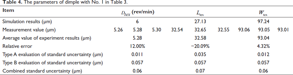
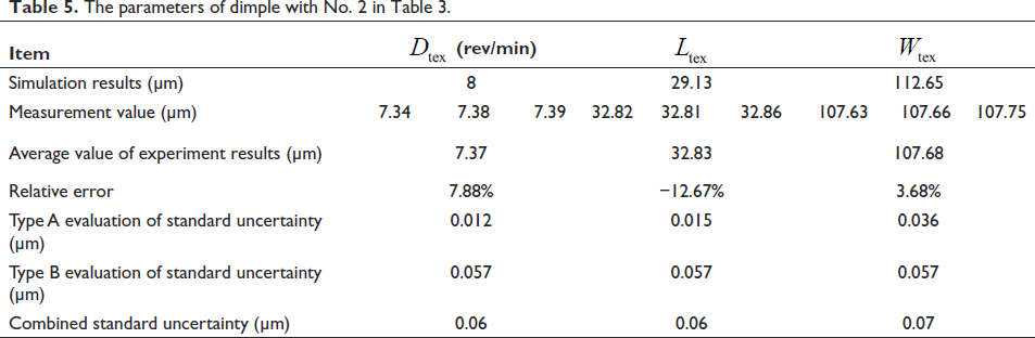
The parameters of the dimple for experiment and simulation with Table 3 parameters Nos. 1–3 are obtained and are listed in Tables 4–6. Each measurement for each parameter of the dimple is repeated three times, and then the average value of the three-time measurements is calculated and taken as the experiment results for the corresponding parameters of the dimple.
The parameters of dimple with No. 1 in Table 3.
The parameters of dimple with No. 2 in Table 3.
The parameters of dimple with No. 3 in Table 3.
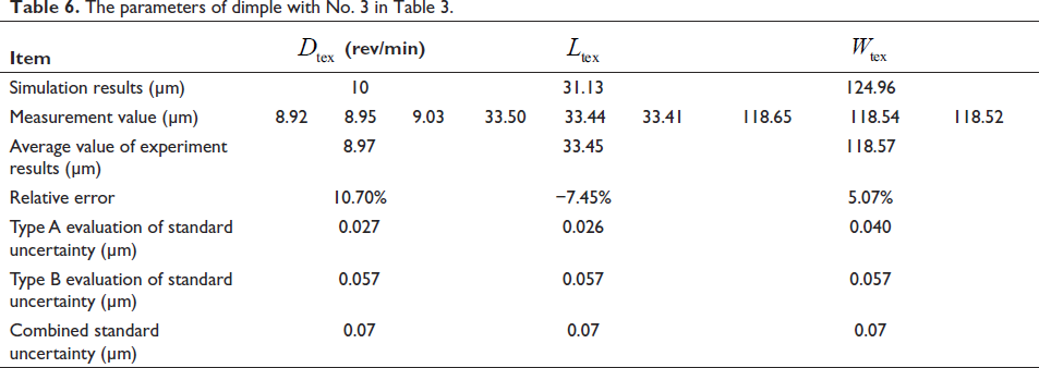
It can be seen from Tables 4–6 that the depth of dimple in the axial direction of the cylinder for experiment results is basically consistent with that of simulation results, the relative error is within 12.00% (the first case is 12%, the second case is 7.88%, and the third case is 10.70%), and the calculated combined standard uncertainty of the depth of dimple shows that the maximum variant range of the depth of dimple is ±0.07 µm. For the length of the dimple in the peripheral direction of the cylinder, the relative errors between experiment results and simulation results are 20.09% for the first case, −12.67% for the second case, and −7.45% for the third case. The calculated combined standard uncertainty ranges from 0.06 to 0.07 µm. The experiment results can basically reflect the simulation results. For the length of the dimple in the axial direction of the cylinder, the experiment results are consistent with the simulation results, and the maximum relative error is 5.07% (the first case is 4.32%, the second case is 3.68%, and the third case is 5.70%), and the maximum variant of the combined standard uncertainty is ±0.07 µm. It can be seen from Tables 4–6 that the combined standard uncertainties in the measurement of dimple parameters are within ±0.07 µm. The uncertainties of measurement data about the dimple parameters are further analyzed in the paper, and it can be concluded that the main factors include personal bias in reading instruments, resolution of the interferometers, and non-uniformity of the samples in the paper.
Although the comparisons for the depth of the dimple in the axial direction of the cylinder, the length of the dimple in the peripheral direction of the cylinder, and the length of the dimple in the axial direction of the cylinder between simulations and experiments show some differences from the comparisons in Tables 4–6, the surface topography of the dimple in simulations basically reflects variant characteristics of the surface topography of the dimple in experiments. The height change of dimples in simulations is approximately equivalent to that of experiments under different depths of cut. The reason for the discrepancies can be attributed to the following three points: (1) the actual material properties in experiments and the setup material properties in simulation models are different; (2) the established simulation models do not include physical factors such as the machining process on dimple topography but only consider geometric factors; and (3) the errors are not completely removed in the microtexturing turning process. In order to decrease these differences, the accuracy of the locus control method for fabricating microtextures can be further improved by considering the compensation of physical factors for the established locus control method. The above comparisons show that the actual generated dimple by the proposed locus control method is basically consistent with the simulation results and verify that the proposed locus control method is effective for generating differently shaped micro-micros in the EVC microtextures process.
Conclusion
In this paper, a novel locus control of EVC is proposed to fabricate intricately shaped microtextures. The generation algorithm of the EVC locus and excitation inputs are studied, and locus control software for elliptical vibration (LocusEVC) is realized. The present work is as follows:
The mechanism of the elliptical vibration-assisted microtexturing process is analyzed and a newly designed 2D resonant ultrasonic vibrator is given to generate the elliptical vibration locus during the cutting process. A locus control method for the elliptical vibration based on microtexture modeling is proposed, and the detailed ideas and mapping process of the locus control are investigated. To realize the mapping process of locus control, the generation algorithm of the elliptical vibration locus based on the discreteness of the microtexturing model is proposed to establish the relationship between the elliptical vibration locus and the discrete points of the microtexturing model. In the mapping process of locus control, the generation algorithm of excitation inputs for the EVC locus is designed to construct the relationship between the EVC locus and the excitation inputs to the actual EVC exciter. The locus control software of the EVC is realized according to the proposed locus control method. A series of micro-dimple cutting and simulation experiments under different machining conditions are performed. The comparisons between experimental results and simulation data show that the proposed locus control method of the EVC is satisfied.
Footnotes
Acknowledgment
This paper was funded by the National Natural Science Foundation of China under grants no. 51675277.
Declaration of Conflicting Interests
The authors declared no potential conflicts of interest with respect to the research, authorship, and/or publication of this article.
Funding
The author received no financial support for the research, authorship and/or publication of this article.