
Abstract
In this article, the effect of vibration amplitude during ultrasonic elliptical vibration–assisted turning on cutting tool flank wear (VBmax) and tool diffusion wear mechanism has been experimentally studied in machining of AISI 4140 hardened steel. To achieve this goal, an ultrasonic elliptical vibration–assisted turning setup was designed and manufactured. This device was then used in both ultrasonic-assisted tuning and ultrasonic elliptical vibration–assisted turning tests (i.e. one-dimensional and two-dimensional ultrasonic-assisted machining). According to the achieved results, ultrasonic elliptical vibration–assisted turning is more effective than ultrasonic-assisted tuning in reducing tool flank wear; at an amplitude of 13 μm, work velocity of 180 mm/s and feed of 0.09 mm/rev, VBmax were decreased 30.3% and 54.3%, respectively, in case of ultrasonic-assisted tuning and ultrasonic elliptical vibration–assisted turning. It was also observed that increasing the amplitude of ultrasonic vibrations reduces VBmax; at work velocity of 180 mm/s and feed of 0.09 mm/rev, the reduction of VBmax in ultrasonic elliptical vibration–assisted turning with amplitudes of 5 and 13 μm is, respectively, 39.3% and 54.3%, compared with that of conventional machining. The results also show that the application of ultrasonic vibrations weakens the cutting tool diffusion wear mechanism. This attenuation is much higher for ultrasonic elliptical vibration–assisted turning in comparison to ultrasonic-assisted tuning. Besides, the amount of attenuation in cutting tool diffusion wear mechanism decreases with increasing vibration amplitude.
Keywords
Introduction
Nowadays, with the remarkable progress in various technologies and industries, the demand for materials with special mechanical and thermal properties has increased. Materials such as hardened steels have received great attention because of their high hardness and wear resistance. 1 These materials, which typically have a hardness of more than 45 HRC, are called difficult to cut materials. During machining of these materials, cutting tools are exposed to large forces and considerable heat is generated in the machining area. Besides, the tendency to create built-up edge and high cutting tool wear are among the challenges of machining these materials. 2 To solve the problem of high cutting tool wear rate in machining of these materials, different methods have been used so far, such as the development of new coatings for cutting tools, new techniques in applying cutting fluids, as well as the development of modern machining processes.
Today, the appearance of cubic boron nitride (CBN) and poly-crystalline cubic boron nitride (PCBN) tools, as well as the application of advanced deposition methods for AlTiN, TiAlN/TiSiN nanocomposite coatings and AlTiCrN nanocrystals, have dramatically increased the cutting tools life in the machining of hard to cut materials; this increase in cutting tool life is mainly because of the effect of these tools in reducing the cutting forces and cutting temperatures.3,4
Alongside dry machining, the emergence of modern lubrication techniques (such as high-pressure cooling, MQL, cryogenic cooling, etc.)5–7 and the development of new cutting fluids (such as nanofluids) 8 have a significant effect on the reduction of force and temperature in cutting zones and, as a result, on the weakening of tool wear mechanisms.9,10
Other techniques for reducing cutting forces and temperatures and thus tool wear in machining processes include the development of hybrid machining processes such as ultrasonic assisted machining (UAM); in this method, high-frequency mechanical vibrations with very small amplitudes are applied to the cutting tool tip and makes the cutting tool to have discontinuous contact with the workpiece. According to the researches in this field, UAM is able to reduce cutting forces, cutting temperature, extend tool life, improve workpiece surface quality, eliminate machining chatter and prevent the creation of build-up edges.11,12
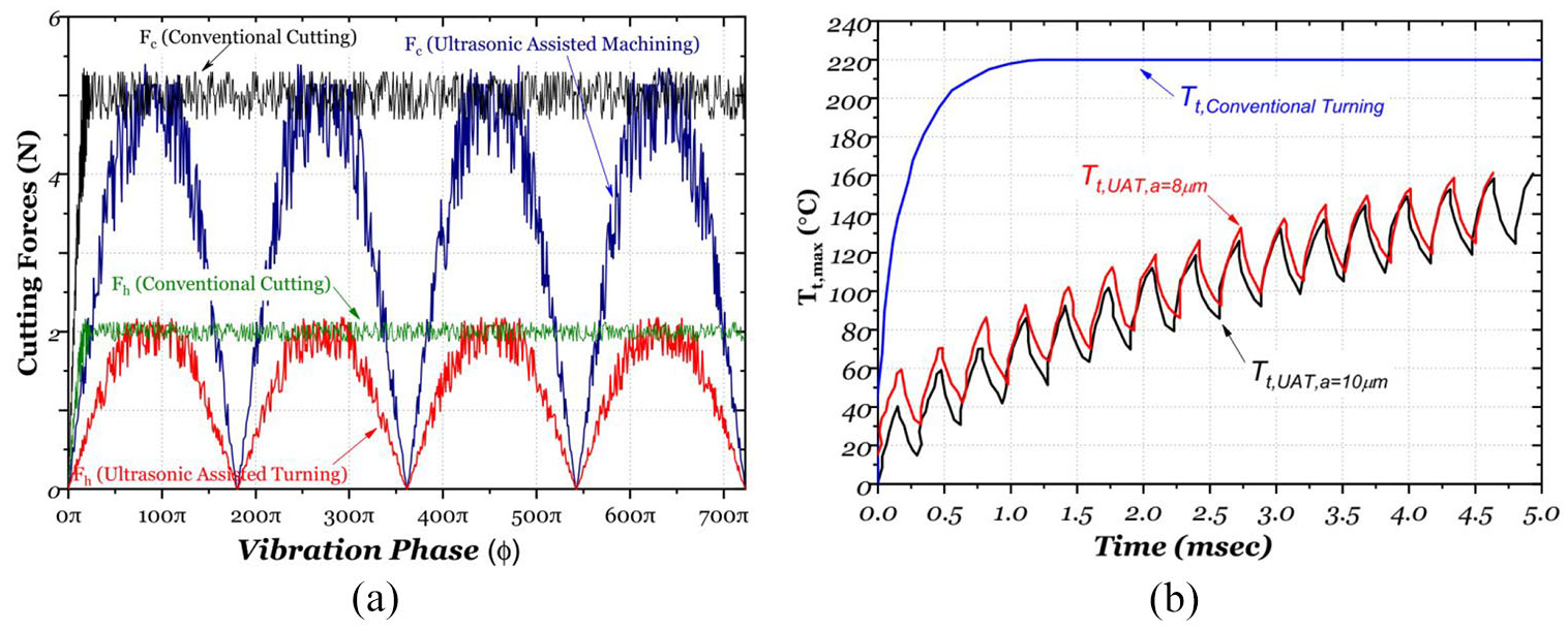
The force applied to the cutting tool and its temperature variations in conventional turning (CT) and UAM are shown in Figure 1. As it can be seen, in case of CT, the cutting tool temperature increases continuously until it finally reaches steady state. Also, the cutting forces in case of CT are almost constant in nature. However, in case of UAM, owing to the separation of cutting tool and workpiece, cutting forces and temperatures have alternating nature, which results in an alternating thermo-mechanical loading on the cutting tool.11,12
In 2007, Nath et al. claimed that cutting tool wear rate in case of UAM was substantially lower than that of CT. They experimentally studied the one-dimensional (1D) ultrasonic-assisted turning (UAT) on low-carbon steel using the CBN tool and found that the cutting forces in this process were about 50.0% smaller than that of CT and that the tool wear was about one-fifth in comparison of CT. The reason is mainly because of the fact that in UAT, the tool temperature is reduced by alternating separation between the tool and the workpiece which weakens the tool wear mechanisms. 13
In another study, in 2009, Nath et al., experimentally studied the ultrasonic elliptical vibration–assisted turning (UEAT) (along cutting speed and depth of cut) using a poly-crystalline diamond (PCD) tool on a tungsten carbide workpiece. According to the results of this study, applying ultrasonic vibrations along depth of cut does not significantly reduce the cutting tool flank wear. 14
In 2010, Zhang et al., experimentally studied UEAT (along cutting speed and depth of cut) using a PCD tool on a hardened steel (49 HRC). According to the results of this study, the application of ultrasonic elliptical vibrations reduces tool wear. They justified this by arguing that in the conventional turning process on this type of steel, the dominant wear mechanism is the chemical diffusion mechanism that is directly related to the cutting temperature. Therefore, they conclude that the use of ultrasonic elliptical vibrations results in a reduction in cutting forces and subsequently a decrease in heat in the cutting zones, causing a decrease in tool wear due to weakening of the chemical diffusion mechanism. 15
In 2012, Deng et al. applied UAT in machining of a SiC/Al2024 composite workpiece using a PCD tool, claimed that applying ultrasonic vibrations reduced tool wear. In addition, the researchers stated that alongside the mechanical wear mechanism, the adhesion mechanism is also one of the main mechanisms of tool wear. They confirmed their findings by examining the tool flank face using the energy dispersive spectroscopy (EDS) method and finding a layer of aluminum and silicon elements on it. 16
In 2014, Zhou et al., performed the experimental study and finite element simulation of UEAT (along cutting speed and depth of cut) on fiber-reinforced polymer (FRP) composites using a tungsten carbide tool with a TiAlN/TiN coating. In CT of this type of composite, owing to the high cutting forces as well as the produced abrasive long fiber, the cutting tool flank wear as well as the depth of the crater wear is remarkable. However, in UEAT, in addition to decreasing cutting forces, the formation of smaller chips will result in reduced tool wear. 17 However, the effect of elliptical vibration on machining temperature and the effect of ultrasonic vibration direction on forces, cutting temperature and tool wear have not been investigated in this study.
In 2014, by experimentally investigating UEAT (along cutting speed and depth of cut) on Inconel 718 by a carbide tool, Lu et al. 18 claimed that the use of ultrasonic elliptical vibrations reduced the cutting tool flank wear. However, in this study, the effects of ultrasonic elliptical vibrations on heat generation and tool wear mechanisms such as chemical diffusion have not been addressed.
In 2016, by combining UEAT and cold plasma, Huang et al. experimentally studied diamond tool wear in the machining of iron-based metals. The results imply the achievement of a novel technology in metal cutting that offers the benefits of vibrational machining (reducing force, reducing temperature and improving surface roughness) along with weakening the chemical diffusion of diamond because of the nitrogen performance in the cold plasma. 19
In 2017, by experimentally examining UAT, Zou et al. investigated the influence of machining parameters (feed, cutting speed, depth of cut and tool relief angle) on tool wear in the machining of a die steel workpiece by a diamond tool and claimed that tool wear occurs mainly at the tool flank face and its dominant mechanisms are graphitization and chemical diffusion. They also stated that ultrasonic vibrations reduce tool wear and weaken chemical diffusion and graphitization mechanisms by 58.0% and 67.0%, respectively. 20 However, in this study, only 1D vibrations have been investigated and the effect of vibration amplitude on tool wear has not been considered.
According to the researches mentioned above, it is concluded that the effect of ultrasonic elliptical vibrations in a plane defined by cutting speed and feed as well as the effect of amplitude of these vibrations on the flank wear is a subject matter that has not been considered by researchers so far. Therefore, the present study is dedicated to the experimental study of the effect of ultrasonic elliptical vibration amplitudes on machining forces, tool temperature and cutting tool flank wear. Finally, the influence of the amplitude of ultrasonic elliptical vibrations on the cutting tool diffusion wear mechanism has been investigated.
UEAT
In UAM, applying ultrasonic vibrations to the cutting tool can be performed one- or two-dimensionally. 12 In the 1D UAT, the cutting tool only vibrates in one direction, Figure 2. Vibration can be applied in the direction of the cutting speed, Figure 2(a), the feed direction, Figure 2(b), or the depth direction, Figure 2(c).
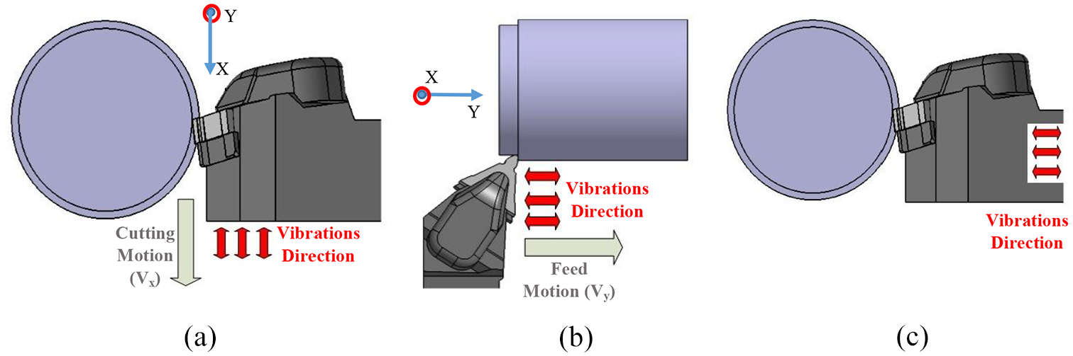
Illustration of the vibration direction of cutting tool in one-dimensional ultrasonic assisted machining. (a) Cutting speed direction. (b) Feed motion direction. (c) Depth of cut direction.
If the ultrasonic vibrations are along the cutting speed, then the tool has a linear and straight-line vibration motion that is superimposed with the cutting motion of the workpiece. If the velocity of the linear motion is shown by Vw, then the position and velocity of the tool at any given moment are determined using equations (1) and (2):


where
In 1D and two-dimensional (2D) vibration systems having a vibrational component in the direction of cutting speed, work velocity (i.e. Vw) has a critical value which is defined by the frequency and amplitude of the vibration that if Vw is greater than that, there is no separation between the tool and the workpiece and vibration does not play a role in the machining process; this critical speed is shown by Vw, crit., and since the cutting speed become zero at the moment of separation, it can be obtained by setting equation (2) equal to zero:

As mentioned, when Vw < Vw,crit., alternating separation of tool and workpiece occurs. In such conditions, the machining forces are of a vibrating nature and the average force will be smaller than that of the CT and, on the other hand, the tool will have the opportunity to cool.11,12
During UEAT, cutting tool vibrates in both speed direction, X-axis in Figure 2(a), and feed direction,Y-axis in Figure 2(b). These harmonic motions can be described with the following equations:


Equations (4) and (5) represent the equation of vibration motion of the tool in the direction of cutting speed and feed, respectively, and the parameters a and b are the amplitude of vibration in the direction of cutting speed and feed, respectively.
These two harmonic motions, equations (4) and (5), are superimposed together during UEAT to define the tool tip locus:
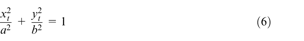
Equation (6) defines the locus of tool tip in UEAT as an ellipses, Figure 3. Using equations (4) and (5), the velocity of cutting tool in speed and feed directions are calculated as following:


According to equation (7), if Vx,w < Vx,w,crit., the separation between the tool and the workpiece will happen along the cutting speed. At the same time, owing to the fact that feed rate (Vy,w = naf) is so small in comparison to the vibrational speed in the feed direction (Vy,w ≪ bω), the separation will occur rapidly by changing the direction of the tool during vibrational motion in feed direction; in other words, the critical value of the feed speed is so large and separation is possible for all small feed values
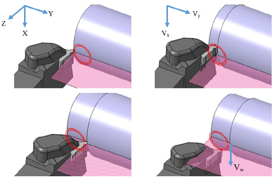
Illustration of tool tip motion path in ultrasonic elliptical vibration–assisted turning (along cutting speed and feed motion).
The duration of engagement between cutting tool and workpiece in case of UEAT is the intersection of the time intervals in which the tool is involved with the workpiece both in feed and cutting speed directions. This time interval is shown in Figure 4(a) in dark gray. In this article, a Visual Basic Code was written to calculate separation time (ts) based on the tool vibration parameters, feed and the work velocity. As shown in Figure 4(a), the separation time of the tool and workpiece (ts) for the same values of the vibration amplitude a = 13 μm, Vw = 180 mm/s and af = 0.09 mm/rev in UAT along feed (UATfeed), UAT along cutting speed (UATspeed) and UEAT is 33.04, 25.21 and 45.64 μs, respectively. Therefore, the cutting time (tc) is much less than that in the 1D case (UATfeed and UATspeed), which allows the tool to have a longer cooling time. As a result, UEAT is expected to weaken wear mechanisms of tool wear more than both UATfeed and UATspeed.
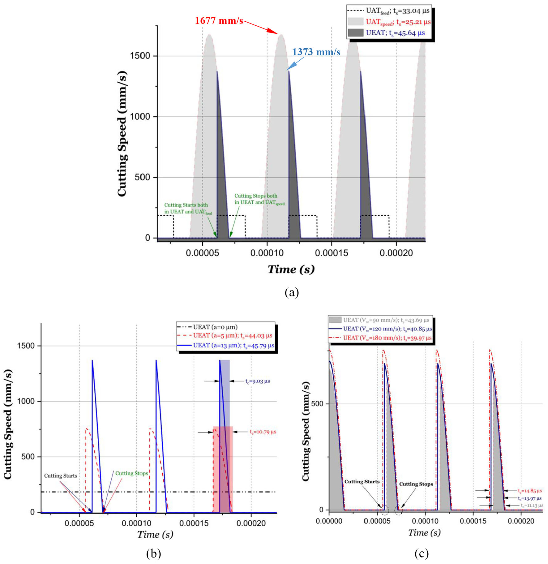
Comparison of separation time in UAT and UEAT. (a) Comparison of ts between UAT and UEAT (Vw = 180 mm/s, af = 0.09 mm/rev and a = 13 μm). (b) The effect of vibration amplitude on ts in case of UEAT (Vw = 180 mm/s, af = 0.09 mm/rev).(c) The effect of Vw on ts in case of UEAT (a = 5 μm, af = 0.09 mm/rev).
In Figure 4(b), the effect of vibrations amplitude on ts is shown in case of UEAT. It is observed that for the same values of Vw = 180 mm/s and af = 0.09 mm/rev, as the vibration amplitude increases from 5 to 13 μm, ts increase from 44.03 to 45.64 μs. As the vibration amplitude increases, the tool separates from the workpiece faster and engages with it for a shorter cutting time. By increasing the vibration amplitude from 5 to 13 μm, tc decreases from 10.79 to 9.03 μs.
In Figure 4(c), the effect of Vw on ts is shown in case of UEAT. It is observed that for the same values of a = 5 μm and af = 0.09 mm/rev for Vw equal to 90, 130 and 180 mm/s, ts will be 43.69, 40.85 and 39.97 μs, respectively. With the increase of Vw, the workpiece reaches the tool faster and involves with the workpiece for a longer period. For Vw equal to 90, 130 and 180 mm/s, tc will be 11.13, 13.97 and 14.85 μs, respectively. Likewise, by comparing the separation time in Figure 4(b) and (c), it is found that with increasing feed, ts decreases. It is observed that for the same values of Vw = 180 mm/s and a = 5 μm, as the feed increases from 0.09 to 0.14 mm/rev, ts decreases from 44.03 to 39.97 μs.
Experimental methodology
Setup for UEAT
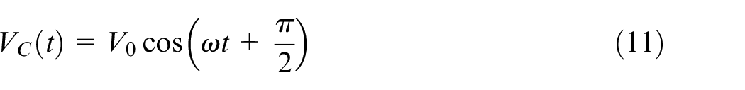
Shown in Figure 5(a) is the tool used in UEAT; it consists of two sandwiched half-ring piezoelectric sets in 90 degree orientation to each other. By separately electrically stimulating, the piezoelectric with the specified phase difference, the cutting tool performs elliptical vibration along both feed and cutting speed and, owing to the presence of the relative velocity between the tool and the workpiece, alternating separations between the tool and the workpiece will occur. The vibrational equation of each piezoelectric is as follows:


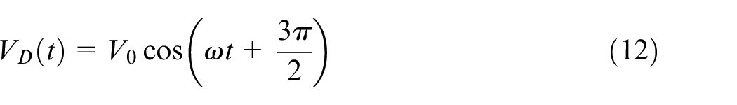
In Figure 5(b), two perpendicular modes of bending vibration are shown. The first mode vibrates at 18212 Hz, and the second mode vibrates at 18268 Hz. The first vibrational mode is bending and has the highest vibrational amplitude along feed. Also, the second bending mode with frequency difference of 36 Hz to the first bending mode has the highest vibrational amplitude along cutting speed. In this way, by stimulating the tool with a frequency of 18240 Hz, the first and second bending modes can be created simultaneously in the tool and the tool tip will traverse an elliptical path on a plane consisting of cutting speed and feed. It should be noted that other vibrational modes before and after these two modes have significant differences with them. For example, the next mode, with a difference of 616 Hz, is located at a frequency far beyond the operating frequency range.
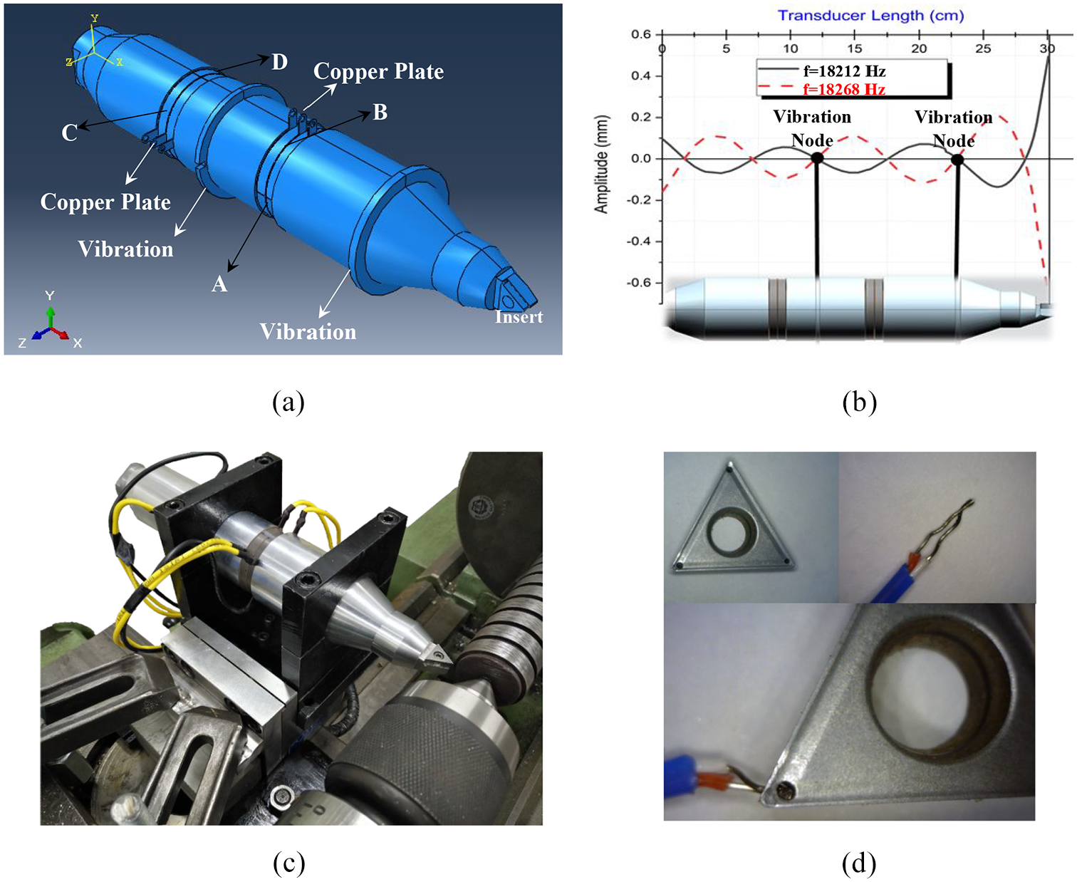
Illustration of the ultrasonic elliptical vibrations assisted turning setup along feed and cutting speed. (a) 3D Model of Vibration tool. (b) Two modes of perpendicular bending vibration. (c) UEAT machining setup. (d) Thermocouple embedded inside the insert.
Design of experiments
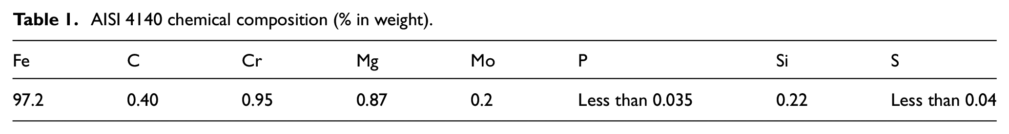
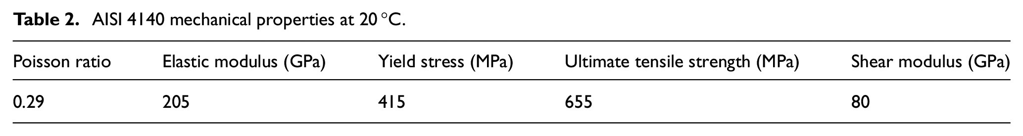
The workpiece was selected as solid shafts made of AISI 4140 steel with a diameter of 40 mm. By heat treatment, the surface hardness of the specimens in a depth of 3 mm increased to 52 ± 2 HRC. Obtained from the quantumetry experiment, the chemical composition of the workpiece is summarized in Table 1. Also the mechanical properties of the workpiece at 20° C obtained by performing uniaxial tensile test are summarized in Table 2.
AISI 4140 chemical composition (% in weight).
AISI 4140 mechanical properties at 20 °C.
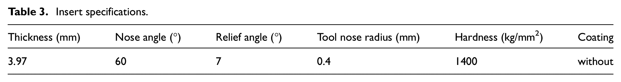
For the experimental tests, the TCMT16T304 F2, HX triangular carbide tungsten carbide insert from Seco, Table 3, and the TN50D lathe were used. In order to hold the tool during the machining process, the transmitter tip is designed in the shape of a tool-holder hole and the insert is fastened tightly by a fine-thread screw, Figure 5(c).
Insert specifications.
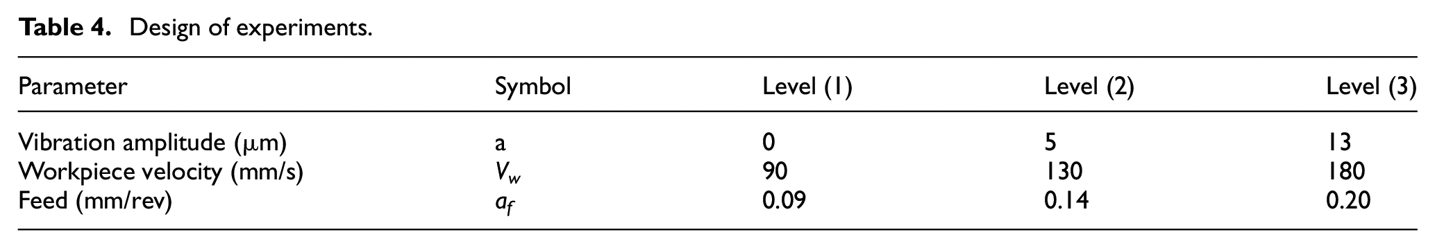
Experimental tests are designed and performed according to the full factorial method, Table 4. Each cutting test was repeated three times, and the average value was recorded. In order to compare the results with that of UATspeed, all experiments of 1D ultrasonic-assisted machining were performed with an amplitude of 13 μm.
Design of experiments.
The Kistler 9257 dynamometer was used to measure the force components. Also, to measure the temperature of the cutting tool during the process, a 735-2 Model Testo was used which records temperature data using Comfort X35 software. The measuring range of the device is from −50 to 1000 °C, and its measurement accuracy is ±0.5 °C. According to Figure 5(d), the thermocouple is embedded inside the insert through a hole created by the super-drill method near the cutting edge.
Measurement of cutting tool flank wear (i.e. VBmax in flank wear land) was done every 6 min at CT, UAT and UEAT tests, Figure 8(a). With respect to some primary tests, irregular wear was observed in zone B; therefore, according to ISO 3685:1993, the maximum width of the flank wear land in the central area of the main cutting edge has been measured using scanning electron microscope (SEM) images. Cutting tool wear experiments were repeated three times for each cutting test and the average value was recorded. In order to omit the effect of previous machining cuts, a new cutting edge was used for each test. In addition, energy dispersive X-ray spectroscopy (EDX) tests were used to study the effect of ultrasonic vibrations on attenuation of diffusion wear mechanism.
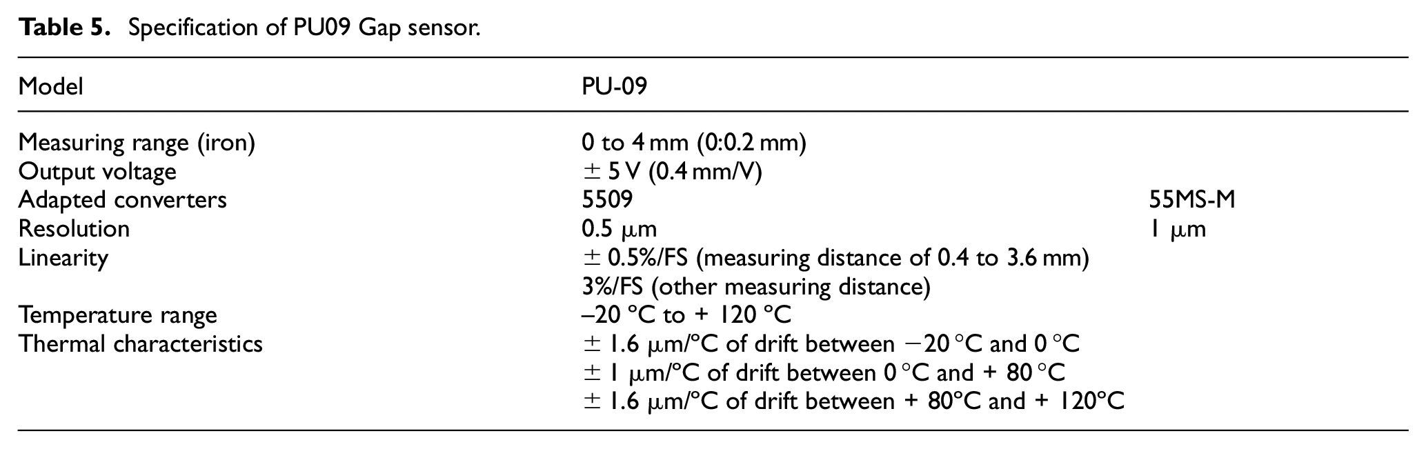
The amplitudes of the ultrasonic vibration in every each perpendicular directions (i.e. feed and speed) were separately measured using a PU09 Gap Sensor and an AEC-5509 converter along with oscilloscope, Table 5. First, a specified input voltage was applied to the set, and then the output voltage was recorded by the oscilloscope. The output voltage was a sinusoidal wave, and by measuring the peak of the diagram, it can be converted to the vibration amplitude.
Specification of PU09 Gap sensor.
Results and discussion
Main cutting force
The results show that in case of UATspeed with a = 13 μm and af = 0.09 mm/rev, with increasing Vw from 90 to 180 mm/s, average reduction in the main component of cutting force (Fc) decreased from 75.6% to 10.0%, Figure 6(a). Therefore, in the mentioned range of machining parameters, UATspeed shows an average reduction of 42.3% compared with CT. This reduction in Fc at af = 0.14 and 0.20 mm/rev is 39.3%, Figure 6(c), and 37.4%, Figure 6(e), respectively.
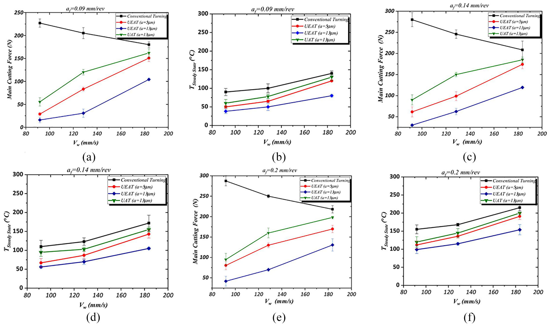
Effect of one- and two-dimensional ultrasonic vibrations on the main component of cutting force and cutting temperature at different values of vibration amplitude, workpiece speed and feed. (a) Main cutting force (af = 0.09 mm/rev).(b) Cutting tool temperature (af = 0.09 mm/rev). (c) Main cutting force (af = 0.14 mm/rev). (d) Cutting tool temperature (af = 0.14 mm/rev). (e) Main cutting force (af = 0.20 mm/rev). (f) Cutting tool temperature (af = 0.20 mm/rev).
In case of UEAT with a = 13 μm and af = 0.09 mm/rev, with increasing Vw from 90 to 180 mm/s, average reduction in the main component of cutting force (Fc) decreased from 93.0% to 42.0%, Figure 6(a). Therefore, in the mentioned range of machining parameters, UEAT shows an average reduction of 73.4% compared with CT; this reduction in Fc at af = 0.14 and 0.20 mm/rev is 68.8%, Figure 6(c), and 65.8%, Figure 6(e), respectively. Therefore, it can be concluded that the effect of UEAT in reducing Fc is greater than that of UATspeed, which is because of the longer separation of tool and workpiece.
In case of UEAT with a = 5 μm and af = 0.09 mm/rev, with increasing Vw from 90 to 180 mm/s, average reduction in the main component of cutting force (Fc) decreased from 87.3% to 16.2%, Figure 6(a). Therefore, in the mentioned range of machining parameters, UEAT shows an average reduction of 54.3% compared with CT; this reduction in Fc at af = 0.14 and 0.20 mm/rev is 51.4%, Figure 6(c), and 47.4%, Figure 6(e), respectively. Therefore, according to Figure 4(b), it can be concluded that as the amplitude of the ultrasonic elliptical vibrations decreases (13 to 5 μm), ts decreases, and as a result, the machining forces in a cutting cycle are zero for a shorter period, and therefore, the average cutting force increases.
Cutting tool temperature
In the present research, UEAT was observed to be more effective in reducing the cutting tool steady state temperature in comparison to UATspeed, Figure 7.
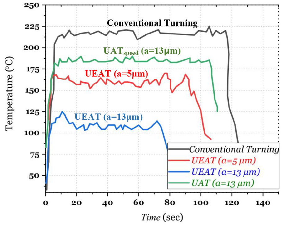
A typical real-time curve of steady state temperature for CT, UATspeed and UEAT (Vw = 180 mm/s and 0.2 mm/rev).
Based on the results of the experimental tests, in UATspeed with a = 13 μm and af = 0.09 mm/rev, with increasing Vw from 90 to 180 mm/s, average reduction in the steady-state temperature decreased from 33.3% to 7.1%, Figure 6(b). Therefore, in the mentioned range of machining parameters, UATspeed shows an average reduction of 20.8% compared with CT; this reduction in steady-state temperature at af = 0.14 and 0.20 mm/rev is 13.3%, Figure 6(d), and 14.4%, Figure 6(f), respectively. It can be explained by the fact that with increasing Vw and approaching to Vw, crit., ts decreases, Figure 4(d), on the other hand, increasing cutting speed will increase heat generation in cutting regions. As a result, the effectiveness of ultrasonic vibrations to reduce cutting temperature weakens with increasing Vw. Therefore, there is a direct relation between steady-state temperature and Vw.
In case of UEAT with a = 13 μm and af = 0.09 mm/rev, with increasing Vw from 90 to 180 mm/s, average reduction in the steady-state temperature decreased from 57.8% to 42.8%, Figure 6(b). Therefore, in the mentioned range of machining parameters, UEAT shows an average reduction of 50.2% compared with CT; this reduction in steady-state temperature at af = 0.14 and 0.20 mm/rev is 43.7%, Figure 6(d), and 32.0%, Figure 6(f), respectively. Therefore, the effect of elliptical vibrations on temperature reduction is greater than that of 1D vibrations, mainly because the tool separation time is longer than that in 1D vibrations, and therefore, the tool has a longer time to cool down.
In case of UEAT with a = 5 μm and af = 0.09 mm/rev, with increasing Vw from 90 to 180 mm/s, average reduction in the steady-state temperature decreased from 44.4% to 14.3%, Figure 6(b). Therefore, in the mentioned range of machining parameters, UEAT shows an average reduction of 31.2% compared with CT; this reduction in steady-state temperature at af = 0.14 and 0.20 mm/rev is 28.4%, Figure 6(d), and 19.3%, Figure 6(f), respectively. Therefore, according to Figure 4(b), it can be concluded that as the amplitude of the ultrasonic elliptical vibrations decreases, ts decreases, and as a result, the cutting tools has a shorter time to cool down, and therefore, the average steady-state temperature decreases.
Cutting tool flank wear
Based on the results of the experimental tests, in UATspeed with a = 13 μm and af = 0.09 mm/rev, with increasing Vw from 90 to 180 mm/s, average reduction in VBmax decreased from 42.1% to 30.3%, Figure 8(a). Therefore, in the mentioned range of machining parameters, UATspeed shows an average reduction of 37.6% compared with CT; this reduction in VBmax at af = 0.14 and 0.20 mm/rev is 32.2%, Figure 8(b), and 22.6%, Figure 8(c), respectively. According to the results, the amount of reduction in VBmax in case of UEAT decreases with increasing Vw; with increasing Vw, ts decreases, Figure 4(b), thereby greater amount of heat generation will enter the cutting regions in smaller cooling time which will intensify tool wear mechanisms. As a result, the effectiveness of ultrasonic vibrations to reduce VBmax weakens with increasing Vw.
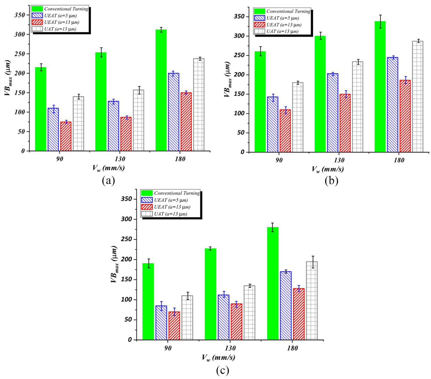
The effect of 1D and 2D ultrasonic vibrations on VBmax at different values of vibration amplitude, workpiece speed and feed. (a) af = 0.09 mm/rev. (b) af = 0.14 mm/rev. (c) af = 0.20 mm/rev.
In case of UEAT with a = 13 μm and af = 0.09 mm/rev, with increasing Vw from 90 to 180 mm/s, average reduction in VBmax decreased from 63.1% to 54.3%, Figure 8(a). Therefore, in the mentioned range of machining parameters, UEAT shows an average reduction of 59.3% compared with CT; this reduction in VBmax at af = 0.14 and 0.20 mm/rev is 57.9%, Figure 8(b), and 50.7%, Figure 8(c), respectively. Therefore, the effect of elliptical vibrations on VBmax reduction is greater than that of 1D vibrations. The reason for this phenomena is mainly because of greater separation time in case of UEAT in comparison to UATspeed, Figure 4(a). As a result, the amount of reduction in cutting forces and heat generation will increase in case of UEAT, and therefore, a greater attenuation in cutting tool wear mechanisms, especially diffusion wear, will take place.
In case of UEAT with a = 5 μm and af = 0.09 mm/rev, with increasing Vw from 90 to 180 mm/s, average reduction in VBmax decreased from 55.3% to 39.3%, Figure 8(a). Therefore, in the mentioned range of machining parameters, UEAT shows an average reduction of 48.4% compared with CT; this reduction in VBmax at af = 0.14 and 0.20 mm/rev is 44.7%, Figure 8(b), and 34.9%, Figure 8(c), respectively. According to the results, the amount of reduction in VBmax in case of UEAT increases with increasing vibration amplitude; with increasing vibration amplitude, ts increases, Figure 4(b), thereby causes a further reduction in machining force and temperature, Figure 6; thus, further weakening in tool wear mechanisms will take place.
Now, additional consideration is given to the cutting speed and how it affects cutting forces, cutting temperature and VBmax. Fernández-Abia et al. 21 studied the effect of cutting speed on cutting forces in high-speed dry turning of austenitic stainless steels; according to the results of this research, the value of cutting forces first decrease with increase in cutting speed and approaches to a minimum value (VΩ), and then shows a progressive trend with increase in cutting speed. As shown in Figure 9, there would be a critical speed (VΩ≈6000 mm/s) over which cutting force increases with increasing in cutting speed. On the other hand, as shown in this figure, while cutting speed reaches to zero, cutting force increases exponentially.
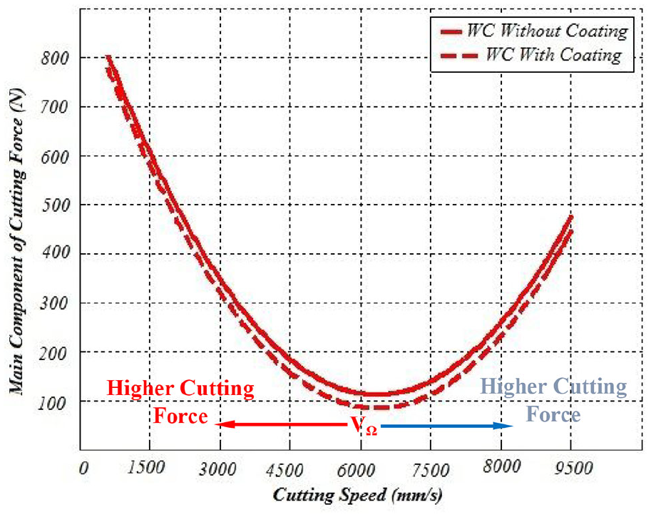
Schematic representation of the effects of cutting speed variation on main cutting force.
The cutting force trend while varying cutting speed is different between CT, UAT and UEAT. In case of CT, as the cutting speed increases, the cutting force decreases, for instance, at af = 0.09 mm/rev, increasing Vw from 90 to 180 mm/s will reduce cutting force about 20.0%. However, during ultrasonic-assisted machining (both UAT and UEAT), cutting speed varies in a wide range from zero to a maximum value, and therefore, cutting force varies from a maximum value to zero. Therefore, the maximum value of cutting force in case of UAM is higher than CT. On the other, cutting force is zero during separation time in each cutting cycle, and therefore, the average of cutting force in each cycle is smaller than cutting force in case of CT. In both UATspeed and UEAT, as the work velocity increases, both the maximum cutting force and separation duration decrease. Therefore, the result is increase in average cutting force.
The cutting temperature increases while increasing cutting speed in CT, UAT and UEAT; increasing cutting speed (Vc) will increase heat flux entering the cutting tool: 11
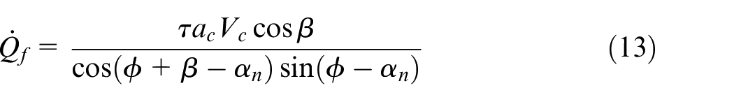
In which, τ is the shear strength of the workpiece material, ϕ is the shear plane angle,
As shown in Figure 4(a), at af = 0.09 mm/rev, a = 13 μm and Vw = 180 mm/s, instantaneous value of cutting speed varies from 0 to 1677 mm/s in case of UATspeed and varies from 0 to 1373 mm/s in case of UEAT; therefore, according to the equation (13), the maximum value of heat flux entering the cutting tool is higher in case of UATspeed than UEAT. So, UEAT provides lower average cutting forces, higher separation time and lower heat flux, and hence, it is more effective in reducing VBmax.
Diffusion wear mechanisms
Figure 10 shows SEM image from cutting tool rake and flank faces after conventional turning at Vw = 180 mm/s and af = 0.2 mm/rev. As can be seen in Figure 10(b), crater wear and wear traces on flank face are obvious. A breakage in cutting edge is also observed in Figure 10(a).
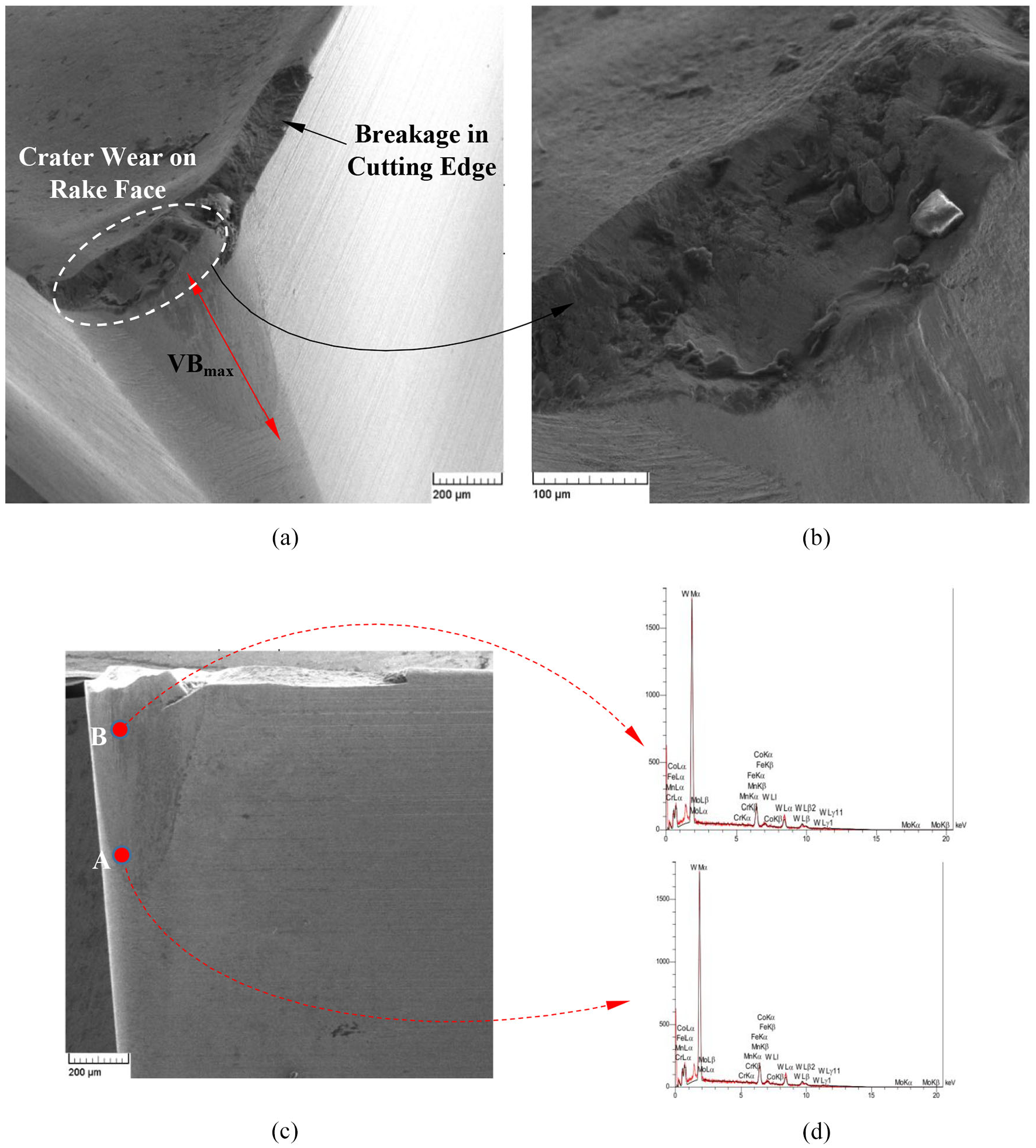
SEM image of cutting tool surface in conventional machining (Vw = 180 mm/s, af = 0.2 mm/rev). (a) Flank wear measurement (VBmax). (b) Crater wear on rake face. (c) Points A and B on flank face. (d) EDX at points A and B.
To study cutting tool diffusion wear mechanism, the percentage of tool elements is determined using EDX analysis. According to the results of this analysis, the chemical composition of the cutting tool before machining comprises 65.0% tungsten and 32.0% carbon. Now, according to Figure 10(c), two points A and B are selected on the tool flank face after conventional machining and EDX analysis is performed on them. The carbon content at points A and B are 9.2% and 3.4%, respectively. Owing to the proximity of point B to the cutting edge and the higher temperature at this area, it can be concluded that this point experiences higher temperatures, thereby loses more carbon due to diffusion mechanism. On the other hand, it is observed that the carbon content at both points is lower than the initial carbon content at these points. Therefore, reducing carbon content by 71.2% and 89.3% at points A and B, respectively, indicates that carbon diffusion from cutting tool to workpiece is one of the mechanisms of tool wear in this machining process.
In Figure 11, SEM image from cutting tool in UATspeed for Vw = 180 mm/s, af = 0.2 mm/rev and an amplitude of 13 μm is illustrated. Similar to the previous case, after machining process, points A and B are selected on the flank face of the cutting tool exactly at the previous locations, and EDX analysis is performed on them. The carbon content in points A and B was 13.6% and 9.6%, respectively. Carbon reductions of 57.3% and 69.9% were observed at points A and B, respectively, which is lower than the corresponding values in conventional machining. Consequently, it can be concluded that the application of ultrasonic vibrations has weakened the mechanism of carbon diffusion. In addition, in this case, the breakage in cutting tool edge is not observed and based on visual observations from SEM images, the crater wear has a smaller depth, Figure 11.
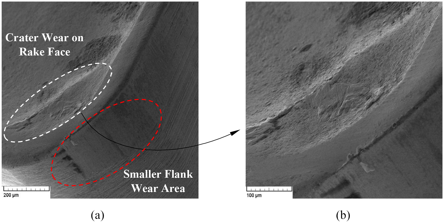
SEM image from cutting tool surfaces after UATspeed machining (Vw = 180 mm/s, af = 0.2 mm/rev, vibration amplitude13 µm). (a) Flank wear. (b) Crater wear on rake face.
In Figure 12, the SEM image from cutting tool flank face and cutting tool edge has been shown after UEAT machining performed with Vw=180 mm/s, af = 0.2 mm/rev and an amplitude of 13 μm. It is observed that the crater wear depth and VBmax have been significantly reduced, but there are signs of fracture on the cutting edge due to the application of cyclic thermo-mechanical loads during the machining process resulting in fatigue failure. Besides, chipping is observed on the cutting edge.
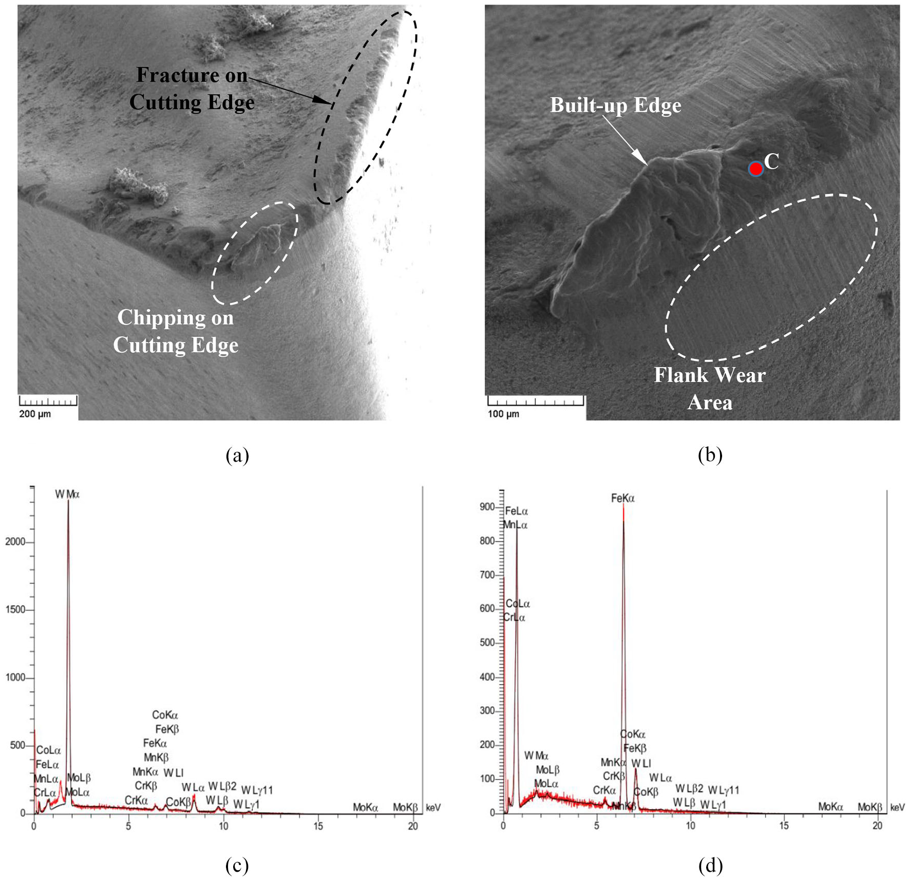
SEM image of cutting tool surface in UEAT (Vw = 180 mm/s, af = 0.2 mm/rev, vibration amplitude 13 µm).
After UEAT machining, EDX analysis is performed on points A, B and C. Points A and B were selected on the tool flank face and precisely in the previous locations. Point C is selected on the chip attached to the cutting edge. The carbon content at points A and B is 15.3% and 12.4%, respectively. Carbon content reductions of 52.0% and 61.4% were observed at points A and B, respectively, which are lower than those corresponding to UATspeed. As a result, it can be concluded that UEAT weaken the mechanism of carbon diffusion much more than UATspeed.
Point C is on the build-up edge and contains 88.0% iron and 6.8% carbon. The decrease in iron content by 9.2% and the increase in carbon content by 6.4% compared with the machined workpiece indicates the diffusion of these two elements from cutting tool to chip and the difference of EDX analysis peaks in Figure 12(c) and (d) illustrates this phenomena.
The percentage of carbon content determined from EDX analysis at point B on the flank face for af = 0.2 mm/rev and at different values of Vw is illustrated in Figure 13. As can be seen, the carbon content in the tool samples involved in UEAT was significantly higher than that of the tools used in the UATspeed and the lowest values are attributed to the cutting tools used in conventional machining. It is also observed that as the vibration amplitude increases, the carbon diffusion mechanism attenuates. Also with increasing Vw, owing to higher heat generation, the diffusion mechanism has significantly intensified and the carbon diffusion rate from the cutting tool has increased.
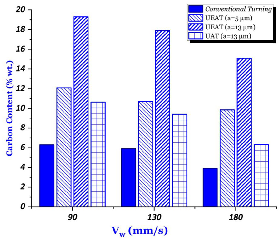
The percentage of carbon content measured from EDX analysis at point B on the flank face of the cutting tool for af = 0.2 mm/rev and at different values of Vw.
Conclusion
In this article, the effect of vibrations amplitude during UEAT on cutting tool flank wear (VBmax) and tool diffusion wear mechanism has been experimentally studied in machining of AISI 4140 hardened steel. The following conclusions are made:
UEAT is more effective in reducing Fc in comparison to UATspeed; at a = 13 μm, Vw = 180 mm/s and af = 0.09 mm/rev average reduction in the main component of cutting force decreased 10.0% and 42.0%, respectively, in case of UAT and UEAT.
UEAT is more effective in reducing machining steady state temperature in comparison to UATspeed; at a = 13 μm, Vw = 180 mm/s and af = 0.09 mm/rev average reduction in the steady-state temperature decreased 7.1% and 42.8%, respectively, in case of UAT and UEAT.
UEAT is more effective in reducing VBmax in comparison to UATspeed; at a = 13 μm, Vw = 180 mm/s and af = 0.09 mm/rev VBmax decreased 30.3% and 54.3%, respectively, in case of UAT and UEAT.
In case of UEAT, increasing the amplitude of the vibrations results in a further decrease in machining force and temperature, thereby further reduction in tool flank wear; at Vw = 180 mm/s and af = 0.09 mm/rev, the reduction of VBmax in UEAT with amplitudes of 5 and 13 μm is, respectively, 39.3% and 54.3%, compared with that of conventional machining.
Applying ultrasonic vibrations in machining AISI 4140 hardened steel using uncoated carbide tungsten weakens cutting tool diffusion wear mechanism. This attenuation is much higher in case of UEAT than UATspeed.
The attenuation in cutting tool diffusion wear mechanism in UEAT of AISI 4140 hardened steel is reduced by increasing the vibration amplitude.
Footnotes
Declaration of conflicting interests
The author(s) declared no potential conflicts of interest with respect to the research, authorship, and/or publication of this article.
Funding
The author(s) received no financial support for the research, authorship, and/or publication of this article.