
Abstract
Ultrasonic-assisted turning is a machining process in which a vibrational displacement (usually in ultrasonic frequencies) is superimposed with the machining displacements in the cutting direction (one-dimensional ultrasonic-assisted turning) or in the cutting direction along with the radial direction (two-dimensional ultrasonic-assisted turning or elliptical ultrasonic–assisted turning). In this research, an elliptical ultrasonic–assisted turning tool is designed in ABAQUS software, in which the longitudinal and bending vibration modes have the minimum resonance frequency difference, so that the resonance of both the vibration modes can be achieved in a definite frequency. A set of half-ring piezoelectric stacks is employed for excitement of the bending mode, and a set of ring-shaped piezoelectric stacks is used for the excitement of the longitudinal mode. There is a phase shift with the amount of π/2 between the longitudinal and bending vibration modes to produce an elliptical vibration. The manufactured tool is employed for machining of copper, which resulted in better surface finish and lower cutting forces.
Keywords
Introduction
Ultrasonic-assisted turning (UAT) is a process in which an ultrasonic vibration is exerted on the tool so that the turning tool engages and disengages periodically with the workpiece. The ultrasonic vibration of the tool can be in one direction (in the cutting direction) or in two directions (the cutting and radial directions), which is called elliptical ultrasonic–assisted turning (EUAT). Some machining parameters are excelled in this process in comparison with conventional machining, including surface finish, tool life and machining forces.
There have been different researches regarding UAT. Overcash and Cuttino 1 designed a tunable vibration turning tool in which a pulse driving technique was used for tool design. However, they did not use the frequently used resonance method. Among other researchers, Ahmed and Sathyan 2 designed a transverse vibration tool for turning of Al 6061. They concluded that using this tool can reduce the cutting force and chip thickness, while improving the surface finish. Ding et al. 3 designed and manufactured a two-dimensional (2D) vibration platform for the 2D vibration-assisted micro end milling of hardened tool steel, which resulted in the surface roughness being improved and the tool wear being reduced in vibration-assisted micro end milling, specifically when compared with the conventional micro end milling. Muhammad et al. 4 combined the UAT and hot machining for β-Ti alloys. And as a result, the improvement of the surface finish and reduction in cutting forces were reported in their research. Maurotto et al. 5 investigated on the advantages of using UAT on titanium and nickel alloys. They used a one-dimensional (1D) UAT tool, indicating that in UAT the cutting forces are reduced, the surface finish is excelled and the maximum material removal rate (MRR) could increase, while there is a reduction in the residual stress on the workpiece. Their method for machining of β-titanium alloy Ti-15-3-3-3 also proved successful. 6 Tabatabaei et al. 7 designed and manufactured a bending mode vibration tool for UAT to investigate the effect of the UAT on the regenerative chatter. They concluded that in some conditions, the UAT could improve the stability of the turning process. Zhang et al. 8 designed an elliptical vibration tool in which the longitudinal and bending vibration modes were used for achievement of the elliptical path. Chang and Bone 9 designed a vibration holder for ultrasonic-assisted drilling tests on Al 6061 T6. Li and Zhang 10 designed and manufactured an elliptical vibration tool which was driven by single actuator. In this research, the tool excitation in longitudinal direction produced an elliptical path in the tool tip. Shamoto et al. 11 proposed an analytical model for prediction of forces in three-dimensional (3D) vibration-assisted turning (VAT) and experimentally verified the results. Celaya et al.12,13 designed and manufactured a novel booster for amplification of the vibration amplitude in which the cross section of the booster varied in the longitudinal direction of the booster. The team specifically focused on the effect of the ultrasonic vibration on the surface quality of the mild steel and concluded that the VAT process excelled the surface quality.
In UAT, the cutting tool vibrates during machining operations. The vibration frequency and amplitude of the cutting tool follow those of the ultrasonic head. The vibration is usually applied with a frequency of about 20 kHz and amplitude of a few microns. 14 As a result, the engagement occurring between the workpiece and the vibrating cutting tool would be intermittent. 14 The average force generated in the periodical cutting is usually less than those happening during the continuous cutting in conventional turning (CT). 14
UAT is employed for machining of an extensive range of hard and soft metallic and nonmetallic materials. Compared to CT, the addition of the ultrasonic vibration to the machining process results in better surface finish of the workpiece, more rapid heat removal from the cutting region and lower cutting forces and stresses. 14 UAT makes feasible the machining of other hard-to-cut materials such as superalloys5,6 and ceramics. 15
The main author used ultrasonic in some manufacturing processes that has improved them. For example, it can reduce friction and seizure length in turning16,17 and thrust force and built-up edge in drilling.18,19
The ultrasonic vibration can be applied along any of the three cutting, longitudinal feed, radial directions or along any combination of them. The tool’s vibration amplitude, z, is expressed as
where a is the vibration amplitude and ω is the ultrasonic vibration angular frequency. The vibration speed of the cutting tool, therefore, would be
The maximum allowable vibration speed can thus be found as follows
in which f is the vibration frequency. To achieve the intermittent engagement between the cutting tool and the workpiece, the cutting speed has to be less than

where vc is the cutting speed. This limitation is imposed only when the vibration is applied along the cutting direction.
In the previous studies, the elliptical tool path was mostly generated by either two bending modes or simply a single bending mode. Although the single bending mode was easy to manufacture, it turned out to be in the design phase difficult to obtain the desirable amplitude ratio of the two directions in the design phase. Furthermore, the longitudinal vibration mode tools are stiffer than the bending modes.
In this article, a new vibration tool was designed and manufactured. ABAQUS finite element method (FEM) software was used for the modal analysis and the design of the tool. The geometry of the tool was obtained after several modal analyses. Some machining experiments were performed after manufacturing the vibration tool. Experiments approved the vibration tool performance. The main contribution of this work is the tool design and manufacture, in which the combination of the longitudinal and bending vibration modes produces an elliptical tool path.
Design of the tool
The longitudinal vibration mode should have a π/2 phase shift in comparison with the bending vibration mode. Since the same amplifier and signal generator were used for excitation of the piezoelectric stacks of both modes, the resonance frequency of both vibration modes had to be as close as possible, and also two sets of piezoelectric stacks were needed for such a tool. The first set of the piezoelectric stacks were ring-shaped stacks located at the end of the tool where there was a longitudinal mode vibration node. These piezoelectric stacks were used for longitudinal mode excitation. The second set of piezoelectric stacks included half-ring-shaped stacks which were used for excitation of the bending mode. These stacks were located on a bending mode vibration node.
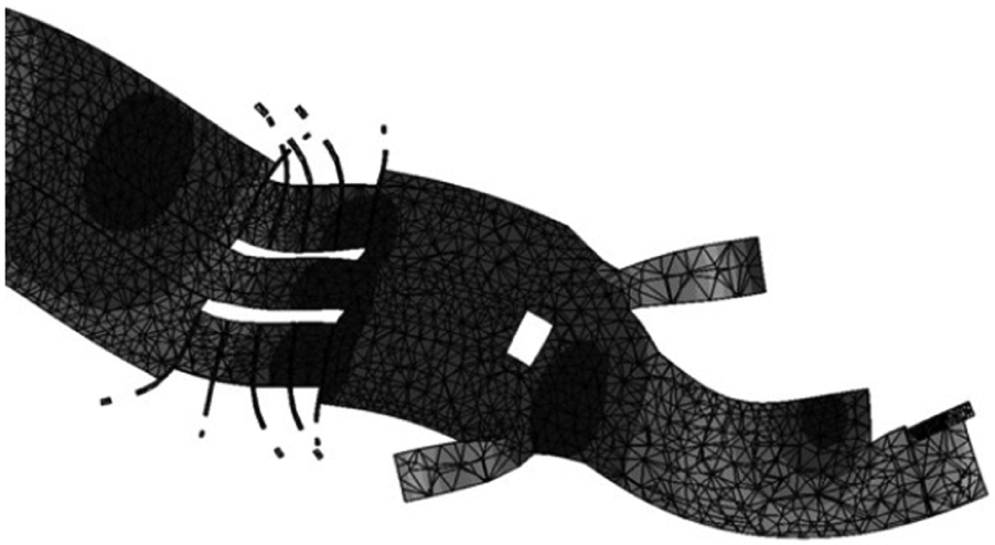
To design the transducer, a primer scheme of the tool was designed and analyzed in ABAQUS software. The optimization of the tool was performed by trial-and-error method until the difference between the longitudinal and bending vibration modes was minimized. Different tool geometries were modeled and analyzed with the software to achieve the optimized geometry in terms of different lengths, shapes and diameters of different tool holder sections. The final design was achieved after 300 times of iterations, which is shown in Figure 1.
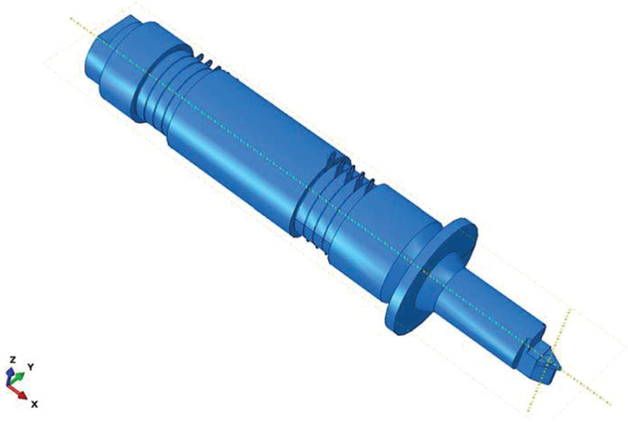
Final design of the EUAT tool.
The piezoelectric stacks’ material was PZT4. The half-rings were located in the upper and lower sides of the transducer. In the piezoelectric layout, the positive sides should be connected to each other and the negative sides of the side stacks should be connected to the body, and thus, negative pole of the electric current was connected to the body. Copper plates with the half-ring shape were used to connect the electric current to the piezoelectric stacks whose layout was similar to that of the piezoelectric stacks. The copper plates of the upper piezoelectric stacks were separated from those of the lower piezoelectric stacks, and some poly tetra fluoro ethylene (PTFE) plates, with the thickness of 1 mm, were used as insulators between the two sets of the copper plates to avoid their connection. To avoid the connection of the copper plates with the central bolt, a PTFE bushing was located between the plates and the bolt (see Figure 6) and so they were excluded from the analysis since there was no stress exerted on the copper plates and the bushing. The polarization direction of the piezoelectric stacks was in the X-axis direction, and there was a phase shift with the amount of π/2 between the current connected to the ring-shaped longitudinal mode piezoelectric stacks and the half-ring-shaped bending mode piezoelectric stacks. Also, there was a phase shift with the amount of π between the upper and the lower half-ring-shaped piezoelectric stacks. So the upper stacks were expanding while the lower ones were contracting. The expansion and contraction frequencies were equal to the natural bending frequency of the transducer, which ended in the bending mode resonating (Figure 2.) A schematic illustration of the control circuit of the transducer is presented in Figure 3.
Expansion and contraction of the upper and lower piezoelectric stacks.
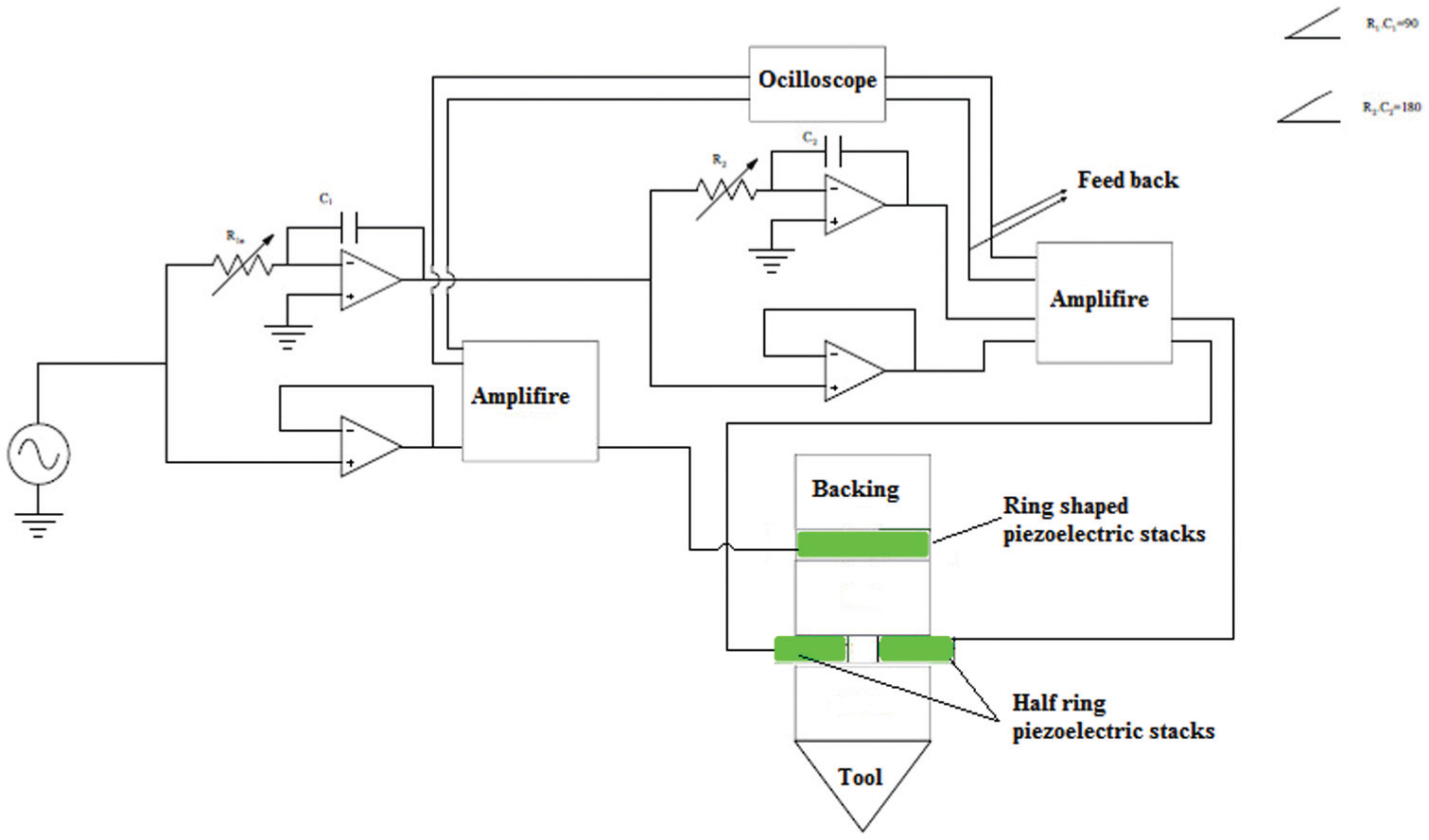
Schematic illustration of the control circuit for excitation of both longitudinal and bending vibration modes.
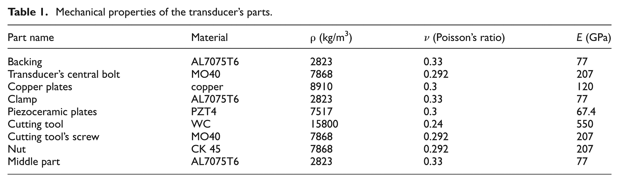
After modeling of the tool, the mechanical properties of the parts should be entered into the software. The necessary parameters for modal analysis were the material’s density, Poisson’s coefficient and the elasticity modulus, which are presented in Table 1.
Mechanical properties of the transducer’s parts.
After meshing, the modal analysis was performed on the model. There were three resonance mode frequencies between 15 and 25 kHz, as shown in Table 2.
Results of the modal analysis.
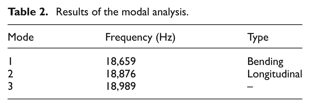
Among the three vibration modes, the following first two modes were appropriate for this tool:
Mode No. 1 was a bending mode in Z-direction with the frequency of 18,659 Hz. The bending mode and its amplitude distribution are shown in Figure 4.
Mode No. 2 was a longitudinal mode with the frequency of 18,876 Hz. This mode along with its amplitude distribution are depicted in Figure 5.
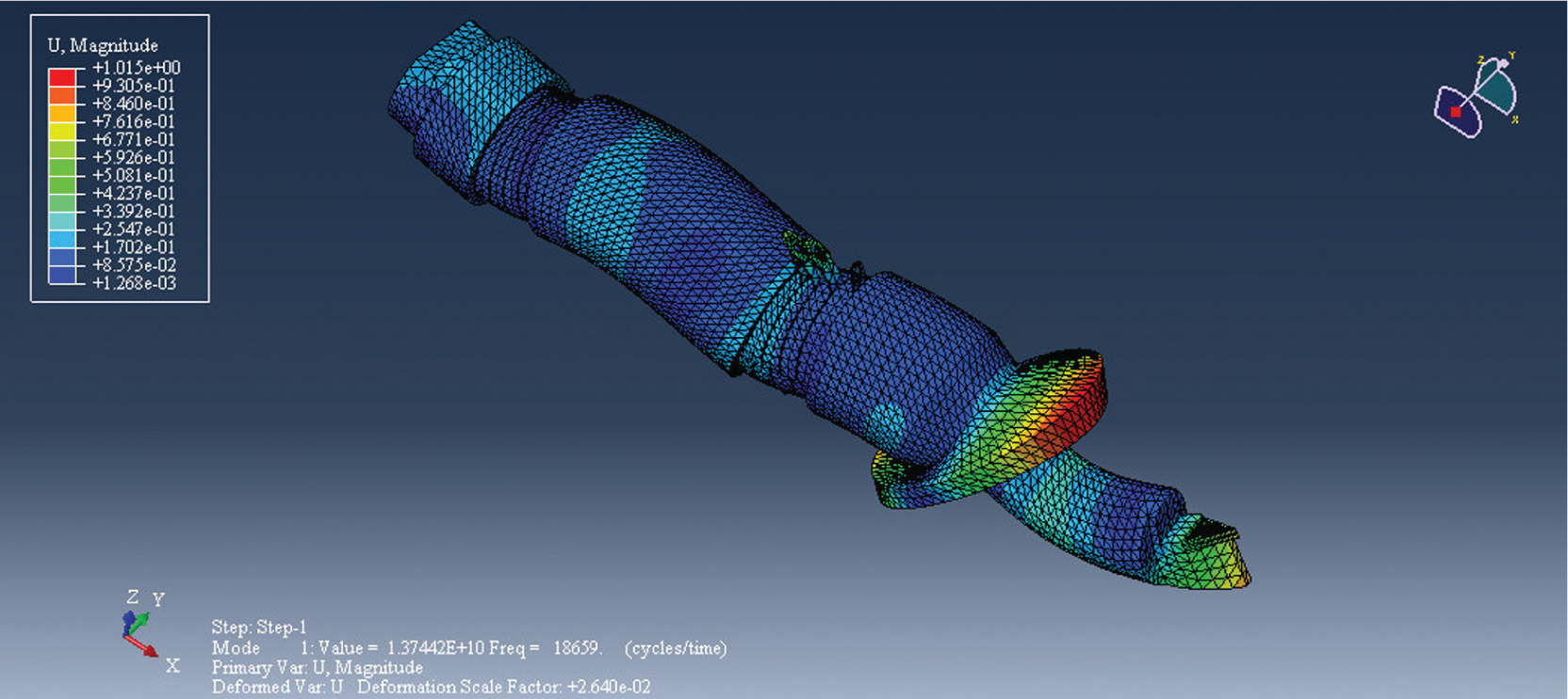
Mode No. 1 and its amplitude distribution.
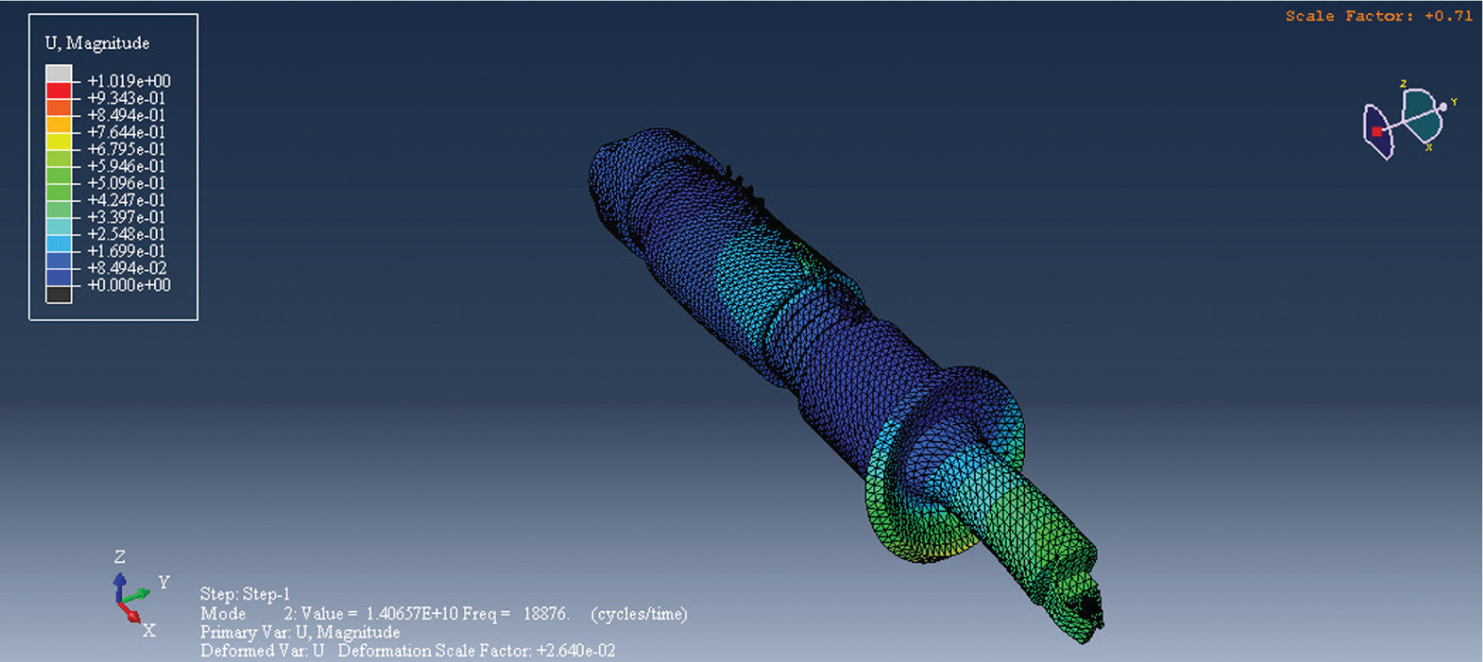
Mode No. 2 and its amplitude distribution.
Obviously, there was no mode between these two modes and their frequency difference was minimized (217 Hz).
Experimental tests
After manufacturing and assembly of the tool parts, a two-channel piezodriver and a single-channel piezodriver were used for excitation of the piezoelectric stacks. The circuit is shown in Figure 3. The single-channel piezodriver was connected to the longitudinal mode piezoelectric stacks and the two-channel piezodriver was connected to the bending mode piezoelectric stacks. After assembly and excitation of the tool, the resonance frequency of two modes was obtained as much as 18.18 kHz. The difference between the analytical and experimental resonance frequency was a result of the difference between the material, manufacturing and assembly conditions of the tool with its ideal analytical condition. The vibration amplitude was measured using an AEC-5509 Eddy Current gap sensor. The vibration amplitude in both directions was 6 µm in the bending mode direction and was 8 µm in the longitudinal mode direction. Finally, the tool assembled on its fixture and on a lathe is illustrated in Figure 6.
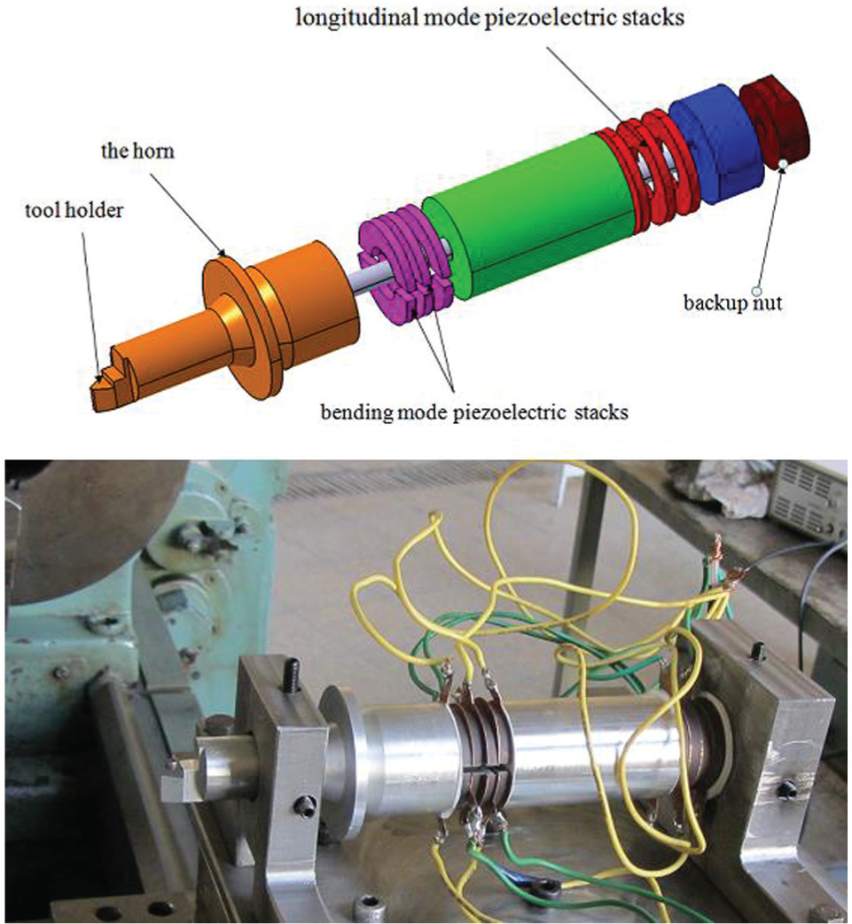
Designed and manufactured tool.
All the experiments were performed without any coolant. The machining force experiments were repeated three times for each of the specimens. The presented results are the average amount of these results. The surface roughness tests, hardness tests and micro-hardness tests were also repeated three times and their average amounts were reported.
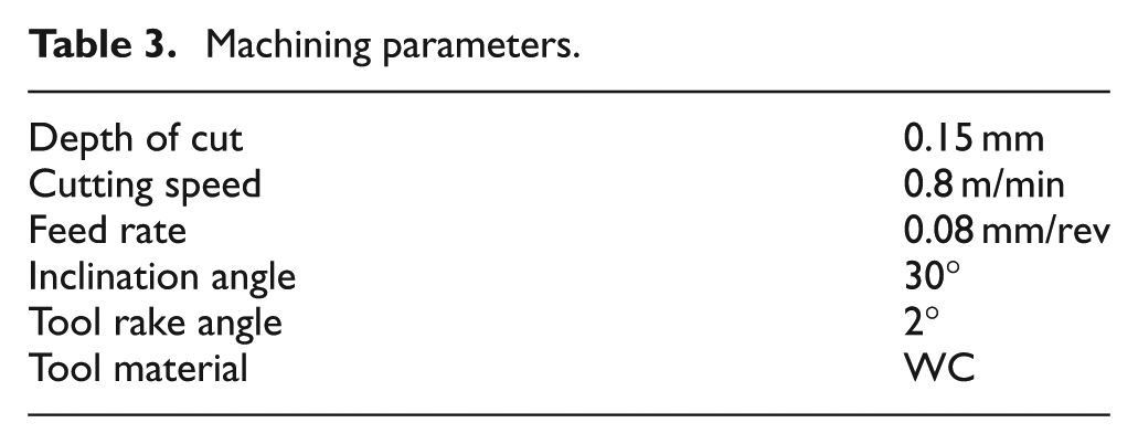
Some machining tests were performed on copper to evaluate the performance of the designed and manufactured tool. The machining and vibration parameters are presented in Tables 3 and 4, respectively.
Machining parameters.
Vibration parameters.
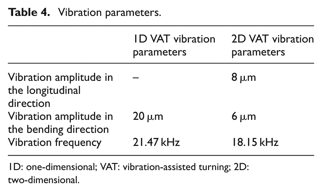
1D: one-dimensional; VAT: vibration-assisted turning; 2D: two-dimensional.
Results and discussion
The amplitudes of measured forces using a KISTLER dynamometer are presented in Table 5.
Machining forces measured in three machining conditions.
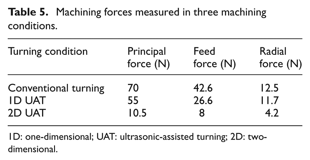
1D: one-dimensional; UAT: ultrasonic-assisted turning; 2D: two-dimensional.
The results clearly show that the machining forces are reduced in UAT experiments. The reduction in the principal force is 21% in 1D UAT and 85% in the 2D UAT. The change in the friction force direction between the chip surface and the tool rake face in a fraction of the vibration cycle resulted in force reduction in 2D UAT, 20 while it could also be a result of the softening phenomenon.
Workpiece properties
The surface of the machined specimen was observed by a visual measurement microscope (VMM), which is shown in Figure 7. In conventional machining, since the built-up edge phenomenon occurred during machining, there were some irregularities on the machined surface (Figure 7(a)). The surface machined with 1D UAT was very smooth, on which the vibration tracks were observable (Figure 7(b)), and the elliptical tool path produced elliptical shape holes on 2D UAT specimen’s surface (Figure 7(c)).
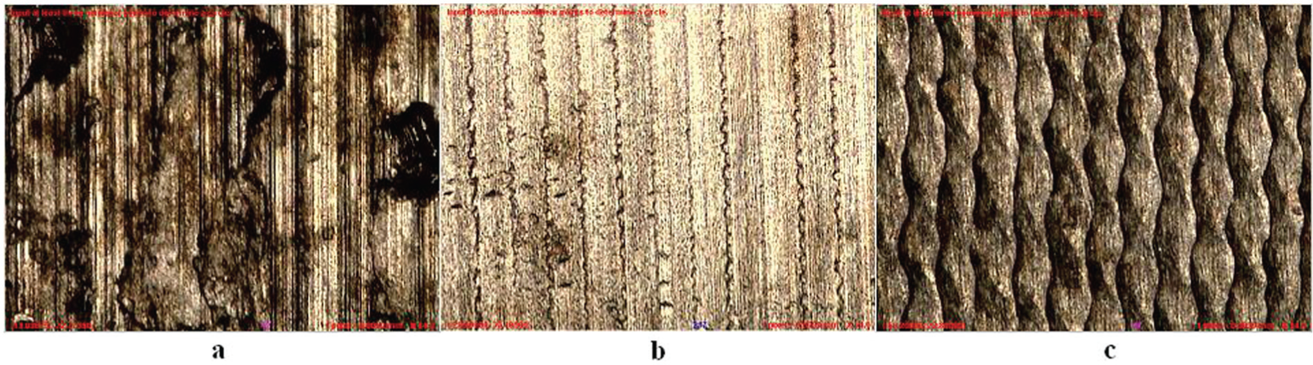
Images of the machined surfaces produced by (a) conventional turning, (b) 1D UAT and (c) 2D UAT, taken by VMM.
Surface roughness
The surface roughness of the machined test specimens was measured using a Mahr surface roughness tester. The surface roughness of each specimen was measured three times, and the average of the measurements is presented in Table 6.
Surface roughness of the machined test specimens.
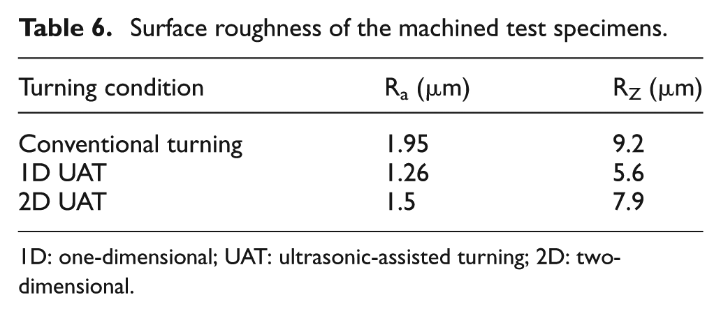
1D: one-dimensional; UAT: ultrasonic-assisted turning; 2D: two-dimensional.
As expected, the surface roughness of the CT test was higher than the specimens machined with UAT. However, the surface roughness of the 1D UAT specimen was lower than that of 2D UAT specimen. This was mainly because of the difference between the vibration amplitudes and frequencies of these two processes. The vibration amplitude and frequency in 1D UAT tool were higher than the vibration amplitude and frequency of 2D UAT (Table 3). In other word, the effect of the vibration amplitude and frequency on the surface roughness was more important than the number of vibration directions.
Specimens’ hardness
The surface hardness of the test specimens was measured and is shown in Table 7.
Results of the workpieces’ surface hardness.
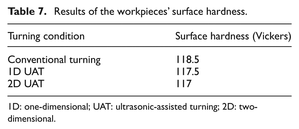
1D: one-dimensional; UAT: ultrasonic-assisted turning; 2D: two-dimensional.
As reported in Table 6, the surface hardness of the test specimens did not have a significant change in UAT. The UAT process had almost no effect on the surface hardness of copper. The deformation caused by the machining mainly occurred in the chip, and not in the workpiece. This is the main reason the change in machining condition was not affected the specimens’ surface hardness.
Chip micro-hardness test
The chips produced by all three machining conditions were sampled, and their hardness was measured using a micro-hardness tester. The micro-hardness of three points of each chip was measured. Their averages are presented in Table 8.
Chips’ micro-hardness results.
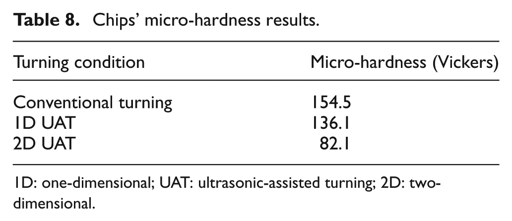
1D: one-dimensional; UAT: ultrasonic-assisted turning; 2D: two-dimensional.
The hardness of the CT specimen was more than that of the other two specimens. It was reduced about 12% in 1D UAT and about 47% in 2D UAT. The chips were softened in UAT, specifically in 2D UAT, in which the softening was more significant. This was also one of the reasons of the significant reduction in machining forces in comparison with CT and 1D UAT (Table 5).
Conclusion
In this research, an elliptical vibration tool was designed in ABAQUS software in which the bending and longitudinal vibration modes have the minimum resonance frequency difference. The excitation of the both the vibration modes, therefore, could be carried out with the same frequency. In the designed tool, a set of ring-shaped piezoelectric stacks were used at the end of the vibration tool for excitation of the longitudinal mode, and a set of half-ring-shaped piezoelectric stacks were used for excitation of the bending mode. There was a phase difference with the amount of π/2 between the vibrations in longitudinal and bending directions which led to the production of an elliptical vibration path in the tool tip. Since all the piezoelectric stacks were preloaded sufficiently, the tool power was significant and the vibration amplitude was acceptable. To study the feasibility of the tool, a set of machining tests were performed on copper. The experiments resulted in the following:
The machining forces reduced in 1D UAT and 2D UAT in comparison with the CT. The amount of the force reduction was more significant in 2D UAT.
The surface roughness excelled in elliptical UAT condition in comparison with the conventional machining condition. The surface roughness of the specimen machined with 1D UAT was better than that machined with 2D. The reason was that the vibration amplitude and frequency of the 1D tool were higher than those in 2D UAT.
The UAT did not affect the specimens’ surface hardness significantly.
The micro-hardness experiments showed that the chips were softened as a result of UAT, specifically in 2D UAT. This observation approved the fact that the vibration in high frequencies may alter the mechanical properties of the surfaces on which the vibration was exerted.
Footnotes
Declaration of conflicting interests
The author(s) declared no potential conflicts of interest with respect to the research, authorship, and/or publication of this article.
Funding
The author(s) disclosed receipt of the following financial support for the research, authorship, and/or publication of this article: The authors are thankful to the University of Kashan for the financial support (Grant No. 2559671/1) of this work.