
Abstract
Keywords
Introduction
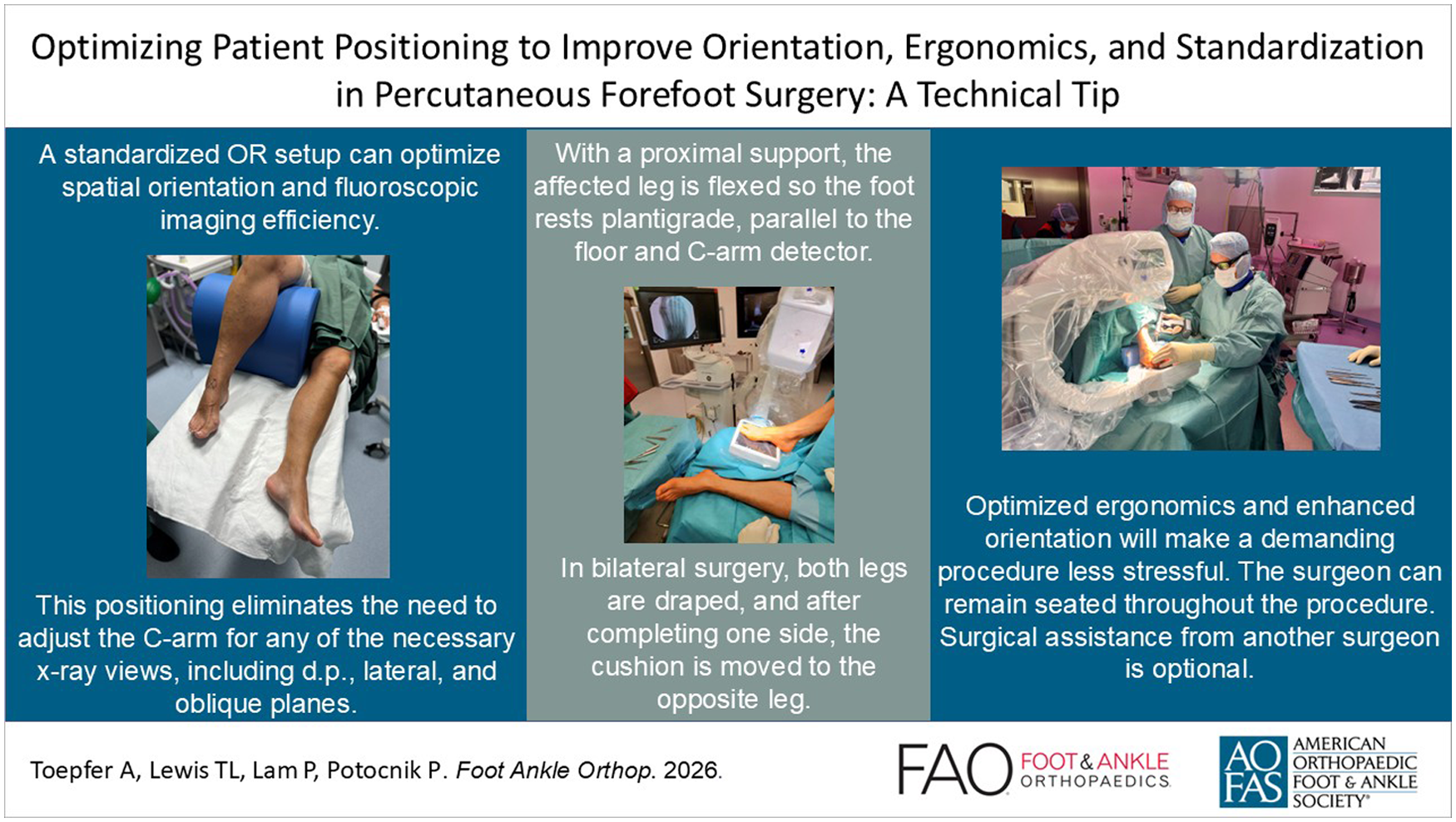
In traditional open surgery for hallux valgus and lesser toe deformities, fluoroscopy is optional and typically used at the surgeon’s discretion to verify and document the final correction. 1 In contrast, modern percutaneous forefoot surgery relies heavily on fluoroscopic guidance, as the small portals limit direct visualization and allow only passage of specialized instruments and burrs. 2 Third- and fourth-generation percutaneous hallux valgus procedures are technically demanding and require substantial practice. 3 While operative time and fluoroscopy use alone do not define the learning curve, studies show that early percutaneous cases involve longer surgeries and greater fluoroscopic exposure than equivalent open procedures—often exceeding 200 images and 2 hours per case.4 -7 Surgeons must learn to interpret visual, haptic, and auditory cues from the burr. Strong 3-dimensional visualization skills and specific percutaneous burr training are essential. A standardized OR setup supports accurate spatial orientation and procedural consistency. 8 The authors present a patient positioning technique that enhances orientation and enables efficient C-arm imaging without additional assistance.
Indications and Contraindications
The authors use this type of patient positioning for any percutaneous forefoot surgery, including procedures of the first ray (fourth-generation metaphyseal extra-articular transverse and akin osteotomy [META], percutaneous Lapidus), distal minimally invasive metatarsal osteotomy (DMMO) and its modifications, minimally invasive lesser toe, and bunionette deformity correction. Moreover, this patient positioning can be used for any other (open) forefoot procedure where repeated use of fluoroscopy is required and enhanced orientation is desired.
Percutaneous hindfoot procedures, such as minimally invasive calcaneal sliding osteotomy (MICO) or percutaneous Zadek osteotomy, are preferably performed in a (floppy) lateral position for the same reasons mentioned above—providing improved orientation and better handling (eg, screw insertion from posterior).
Technique
Irrespective of whether a standard or mini–C-arm is used, patient positioning is the same. When using a conventional C-arm, a radiolucent operation table is used and additional radiation protection is applied for both the patient and the surgeon. In minimally invasive chevron and Akin osteotomy (MICA)/META, the surgeon will be seated on the contralateral side parallel to the patient to enable surgery from the medial aspect of the affected foot. A radiation protection mat can be attached to the respective side of the operation table to reduce exposure to scatter radiation (Figure 1). As previously demonstrated in percutaneous coronary procedures, the use of an adjunctive protective shield placed under the operation table is associated with a significant reduction in operator radiation exposure. 9 The “drape under table shield” can be easily applied to any standard operating table and does not limit the free movement of the surgeon of the C-arm (if needed for additional procedures). Optional radiation protection for the surgeon in addition to a lead apron includes a special x-ray protection thyroid collar, glasses, and headpiece.

When using a standard C-arm, scatter radiation and operator exposure can be minimized by employing a drape-under-table lead shield.
After anesthesia, which is performed to the preference of the surgeon and their patients, the patient is placed in a supine position. With the help of an adequate support under the knee and placed as proximal as possible to the buttock, the affected leg is flexed in the hip and knee so the foot is placed in a plantigrade position in relation to the operating table, parallel to the floor and the detector of the C-arm (Figure 2). Patients with hip or knee replacement do not constitute a contraindication for this positioning. A minimum knee flexion of approximately 90° is considered favorable and should be evaluated prior to surgery. For patients with higher BMI or restricted hip/knee flexion, the C-arm may be tilted to keep the detector parallel to the foot (Figure 3, A and B). The device’s varying sizes allow accommodation for different body types (Figure 4, A and B).

To enhance intraoperative orientation and handling, the operative foot is positioned plantigrade relative to the operating table and floor. A custom-made support is used to achieve flexion at the hip and knee, allowing the foot to be placed plantigrade on the operating table or, when a mini–C-arm is used, directly on the detector. The contralateral leg can be lowered to facilitate access from the surgeon’s seated position.

In patients with limited hip or knee flexion preventing a plantigrade foot position on the operating table, the C-arm can be tilted accordingly (A). In the right image (B), the surgeon is shown wearing radiation-protective gloves. The use of different mini–C-arm systems, including battery-powered units as illustrated in panel B, can help to further reduce radiation exposure.

The custom-made cushions are available in 3 different sizes, accommodating variations in patient anatomy and leg length (A). Strap holders integrated into the base of the cushions allow for stable fixation to the operating table (B).
This positioning facilitates intraoperative orientation and fluoroscopy enormously without the need to change the position of the C-arm for any of the required radiographic planes (dorsoplantar, lateral and oblique).
The leg to be operated on is prepared in a standard sterile manner and draped up to just below the knee joint. This arrangement allows for easier repositioning of the foot later when obtaining the lateral radiographic image. Bilateral operations are performed in the same way, except that initially both feet are washed and draped simultaneously and then a double-hole drape is used. The part of the table with the contralateral leg that is not being operated on can be slightly lowered to facilitate access to the affected foot from the medial aspect.
Surgeon’s Seating Position in Percutaneous Hallux Valgus Surgery vs Lesser Ray Surgery
In third- and fourth-generation percutaneous hallux valgus procedures, the surgeon is seated on the contralateral side and approaches the first ray from the medial aspect (Figure 5). These procedures (MICA/META) are frequently combined with additional minimally invasive corrections of the lesser toes or DMMOs (distal minimally invasive metatarsal osteotomies). For this part of the operation, the surgeon simply moves their chair to the end of the table—no repositioning of the C-arm is required (Figure 6).

A safe, comfortable environment and a standardized setup are key to successful surgery. During minimally invasive chevron and Akin osteotomy (MICA)/ metaphyseal extra-articular transverse and akin osteotomy (META) procedures, the surgeon approaches the operative foot from the medial aspect while seated at the contralateral side. The contralateral leg can be lowered to improve access and enhance ergonomic comfort.

When performing (additional) percutaneous lesser toe correction or DMMO, the surgeon moves to a seated position at the end of the operating table. The standard-sized or mini–C-arm does not need to be repositioned.
If a tailor’s bunion correction is indicated, the C-arm can be positioned distally along the table, enabling the surgeon to approach the foot laterally without any obstruction.
Three-plane Fluoroscopic Imaging Without Repositioning the C-arm
When using a mini–C-arm, the affected foot is positioned directly on the detector and remains there throughout the procedure, except when obtaining a lateral view. The fluoroscopy unit itself does not need to be repositioned or adjusted during the surgery, regardless of the C-arm’s type or size. A dorsoplantar weightbearing radiographic can be simulated by applying pressure to the foot while it rests on the mini–C-arm detector or on the operating table when using a conventional C-arm (Figure 7A).
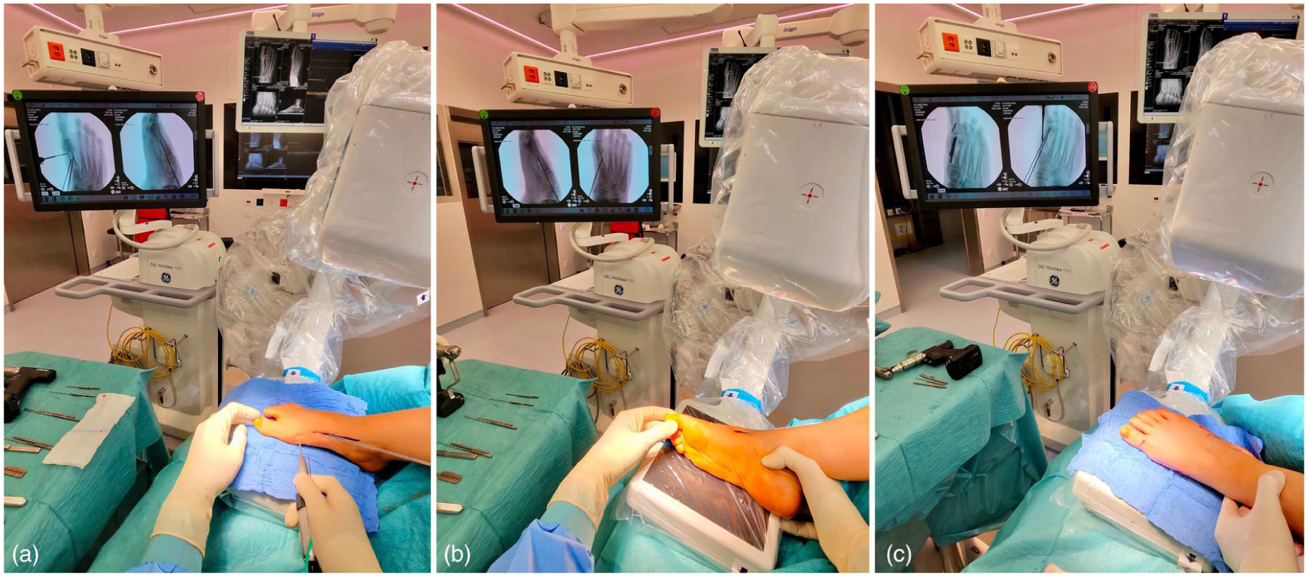
Different surgical steps of fourth-generation percutaneous hallux valgus correction using our specific patient positioning are illustrated. (A) Dorsoplantar fluoroscopic view during first metatarsal osteotomy, with guide wires for the beveled cannulated screw already in place. (B) Lateral fluoroscopic view during guidewire positioning. The leg is externally rotated at the hip until a true lateral view is obtained. (C) Oblique fluoroscopic view achieved by slight internal rotation of the leg, which aids in confirming correct guidewire positioning and appropriate screw length. The authors recommend not relying solely on dorsoplantar and lateral views.
The lateral view is achieved by externally rotating the hip. It is important to ensure a true lateral image with symmetrical projection of the talar dome and adequate visualization of the base of the fifth metatarsal, matching the preoperative weightbearing lateral images (Figures 7B and 8).

Lateral view with a standard-sized C-arm. External rotation of the leg permits accurate lateral fluoroscopy of the operated foot without repositioning the C-arm.
The internal oblique view—used to evaluate the guidewire and screw length as well as the adequacy of dorso-medial prominence resection—can be easily obtained through slight internal rotation of the hip (Figure 7C).
Discussion and Conclusion
As noted by Bonnaig et al, 10 correct patient positioning is an often underestimated yet crucial component of surgical preparation, and careful positioning can significantly reduce the risk of perioperative complications. This becomes particularly important when adopting new surgical techniques that involve previously unfamiliar tools and instruments.
Initial attempts to position the foot in the desired plantigrade orientation during surgery included the use of a carbon triangle typically applied for tibial nailing, but this construct proved too unstable. A leg holder was also tested but restricted the positional adjustments required for lateral radiography. Subsequently, a semicircular support cushion from spinal surgery was tried with promising results (Figure 9). Building on this success, custom cushions were designed in 3 different sizes. These were later refined and equipped with additional strap holders to prevent displacement under the sterile drapes (Figure 4, A and B).
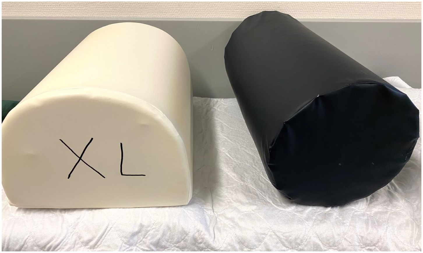
Initial efforts to achieve a plantigrade foot position intraoperatively involved repurposing support cushions from spine surgery. However, it soon became apparent that multiple sizes and a dedicated fixation mechanism to secure the cushion to the table were required.
Patient positioning is typically not covered in sawbone or cadaveric MIS workshops, and many surgeons may not have easy access to clinical observation opportunities with experienced MIS practitioners. It is crucial that each surgeon establishes a setup that guarantees procedural safety, comfort, and reproducibility according to their specific needs. Optimized ergonomics and enhanced orientation will make a demanding procedure less stressful. 11 A key advantage of this technique is that the surgeon can remain seated throughout the procedure. Energy expenditure is significantly lower in a seated than in a standing position, 12 and studies in other surgical subspecialties have shown improved comfort and reduced physical strain when operating while seated.13,14 Given that operating rooms are the most cost-intensive hospital units, optimized room setup and ergonomics may contribute to greater efficiency, economic sustainability, and procedural safety, ultimately supporting high-quality patient care. 8
As a limitation to this technique, bimanual dexterity is beneficial as the surgeon will always approach the foot from the medial side and depending on the side being operated on and the surgeon’s dominant hand, guidewire and screw placement may need to be executed with the non-dominant hand. Naturally, there is no single solution that is universally optimal for all needs. Different preferences might warrant a different type of positioning. The patient positioning technique described here has been employed in our clinics for more than 8 years and can aid in improving surgical orientation, thereby facilitating a smoother transition from open to percutaneous forefoot surgery.
Supplemental Material
sj-pdf-1-fao-10.1177_24730114261436763 – Supplemental material for Optimizing Patient Positioning to Improve Orientation, Ergonomics, and Standardization in Percutaneous Forefoot Surgery: A Technical Tip
Supplemental material, sj-pdf-1-fao-10.1177_24730114261436763 for Optimizing Patient Positioning to Improve Orientation, Ergonomics, and Standardization in Percutaneous Forefoot Surgery: A Technical Tip by Andreas Toepfer, Thomas L. Lewis, Peter Lam and Primoz Potocnik in Foot & Ankle Orthopaedics
Footnotes
ORCID iDs
Ethical considerations
Ethical approval was not required
Consent to publish
Informed consent for publication was provided by the participant.
Funding
The authors received no financial support for the research, authorship, and/or publication of this article.
Declaration of Conflicting Interests
The authors declared the following potential conflicts of interest with respect to the research, authorship, and/or publication of this article: Thomas Lewis, MD, PhD, reports PhD tuition fees supported by MIFAS and consulting fees from Vilex. Disclosure forms for all authors are available online.
Supplemental Material
A supplemental video for this article is available online.
References
Supplementary Material
Please find the following supplemental material available below.
For Open Access articles published under a Creative Commons License, all supplemental material carries the same license as the article it is associated with.
For non-Open Access articles published, all supplemental material carries a non-exclusive license, and permission requests for re-use of supplemental material or any part of supplemental material shall be sent directly to the copyright owner as specified in the copyright notice associated with the article.