
Abstract
Technicians in a commercial laboratory manually uncap up to 700 sample tubes daily in preparation for bioanalytical testing. Manually twisting off sample tube caps not only is a time-consuming task, but also poses increased risk for muscle fatigue and repetitive-motion injuries. An automated device capable of uncapping sample tubes at a rate faster than the current workflow would be valuable for minimizing strain on technicians’ hands and saving time. Although several commercial sample tube–uncapping products exist, they are not always usable for a workload that uses a mix of tube sizes and specific workflow. A functioning uncapping device was developed that can semi-automatically uncap sample tubes with three different heights and diameters and was compatible with the workflow in a commercial laboratory setting. Under limited testing, the average success rate with uncapping each of the three sample tube sizes or a mix of them was 90% or more, more than three times faster than manual uncapping, and met standard acceptance criteria using mass spectrometry. Our device with its current performance is still a prototype, requiring further development. It showed promise for ergonomic benefit to the laboratory technicians, however, reducing the necessity to manually unscrew caps.
Introduction
Bioanalytical testing is a common method used for studying various kinds of samples, such as ecological, nutritional, or biological samples. These samples are generally sent to commercial bioanalytical testing laboratories in sample tubes of different sizes and types. For example, nutritional and biological samples in smaller quantities are transported in sample tubes. Technicians who process these samples must complete the repetitive task of opening and closing the small sample tubes each time the sample is accessed, sometimes up to 700 sample tubes each day. New laboratory assays are constantly being developed and tested, and the Bureau of Labor Statistics projects a growth of 13% from 2014 to 2024 in terms of employment opportunities in the field of bioanalytical testing, adding 42,700 professionals to the 335,700 already in the field (as of 2016). 1
This repetitive task increases the risk for occupational injuries and musculoskeletal disorders (MSD) such as carpal tunnel syndrome. According to the U.S. Department of Labor, of all work-related repetitive injuries, MSD results in more days away from work than any other workplace injury. 2 Such disorders cost industry roughly $15–20 billion annually, not including indirect costs. 3 Some of the risk factors for these disorders include repeated and forceful wrist flexion and extension, radial and ulnar deviation, and forearm supination and pronation, all of which combine to produce the motion of screwing small caps on and off sample tubes. Musculoskeletal injuries are becoming increasingly prevalent among laboratory workers due to the high volume of work. 2 Simple tasks such as repeated uncapping and capping of sample tubes cause significant stress to the wrists and hands. Greater manual effort is required to remove the top of screw-on/threaded sample tubes compared to a nonthreaded, stoppered sample tube, making the technicians even more susceptible to hand injury.2,4,5
Several designs of capping and de-capping systems are available in the literature, and some products are commercially available. Owen et al. describe a capping/de-capping system consisting of spindles and sockets aligned with sample tubes. 6 Cohen et al. offer a de-capping system consisting of upper grippers to hold the caps stationary, while lower grippers rotate the test tube and translate it downward, thus causing the de-capping action. Sensors are provided to detect the level of liquid in the sample tube after the caps are removed and detect any spillage from the test tubes onto the lower grippers. 7 Thomas et al. describe a power hand tool with a motorized shaft that rotates and a motorized plunger and a set of jaws for holding the sample tube cap. 8 Schacher presents an extensive de-capping/recapping system in which the sample tubes are de-capped, processed, and later recapped with their respective caps. 9
Several commercial products currently on the market accomplish the task of automatically capping and uncapping screw-top sample tubes, sometimes uncapping up to 96 sample tubes simultaneously, or one row at a time to minimize contamination. Each product approaches the problem with a unique mechanism, yet many baseline characteristics are shared among them. In each of the product designs, a tray of sample tubes is placed or inserted in the area designated for the uncapping to occur. The sample tubes for some of these machines have specific tops in which a hexagonal or octagonal hole is cut out for the screw or arm of the device to reach down and insert into. This allows the top to either be screwed off or screwed onto the tube. The machine is capable of recognizing different tray types and sizes, so until the exact same tray is placed back into the device, the machine will not replace the tops on the sample tube. Some of the systems also include a robotic arm that maneuvers its way around the interior, thus uncapping and capping specified sample tubes one at a time.10–15
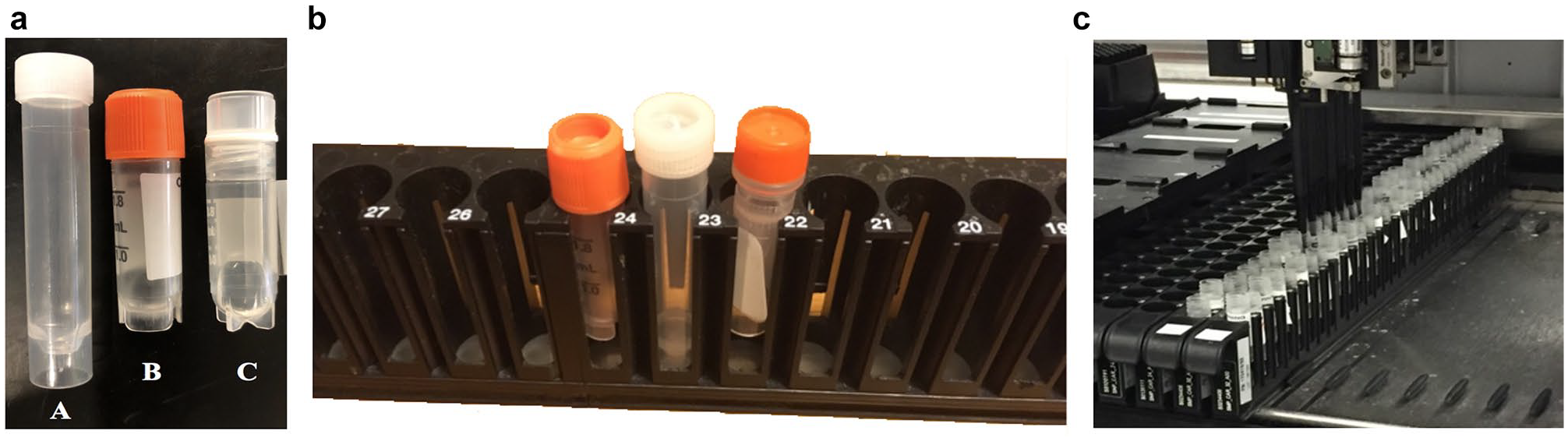
These uncapping products are insufficient for contract laboratories. Many laboratory workflows do not support uncapping devices that require uniform caps or tubes. Various sample tubes are often handled together. The specific workflow depends on the test being performed and the sources of the samples. Certain testing laboratory workflows do not support uncapping devices limited to uniform caps, and various kinds of sample tubes are often handled together depending on the test being performed, as shown in Figure 1a . We therefore designed a device to cap and uncap tubes of multiple formats and sizes. Many types of tubes are compatible with the rack shown in Figure 1 .
(
The objective of the project was to create an uncapping device for a specific workflow in a testing laboratory, measure its success rate for uncapping sample tubes of three different diameters, compare the time needed to uncap the sample tubes against the manual method, determine the ability of the device to collect these removed caps in a cap-catching drawer, and estimate the cross-contamination of the sample tubes during the uncapping process.
Design and Methods
The uncapping device shown in
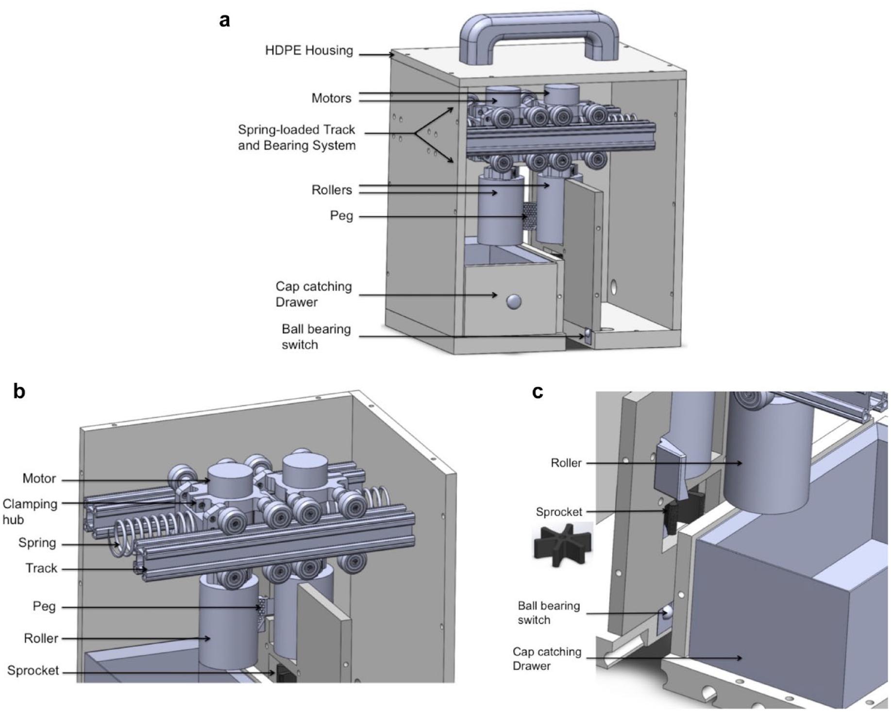
A three-dimensional (3D) computer-aided design (CAD) model of (
(
Springs (Compress Spring, Precision, 2 In, Grainger) are placed horizontally in compression between the sidewalls and the sliding body (motors, rollers, and bearings), effectively providing resistance when the bodies are displaced as the tubes are pushed through the device, as shown in
Below one roller is a six-pronged sprocket that mates with the gaps in the sample tube rack, effectively preventing the sample tubes from spinning freely during uncapping, as shown in Figure 2c . The sprocket shown as an insert in Figure 2c is fabricated using a stereolithography (SLA) 3D printer (Formlabs Form 2, Formlabs, Somerville, MA) with flexible resin (Formlabs flexible resin, 80A Shore durometer, Formlabs) to improve grip strength for the sample tubes.
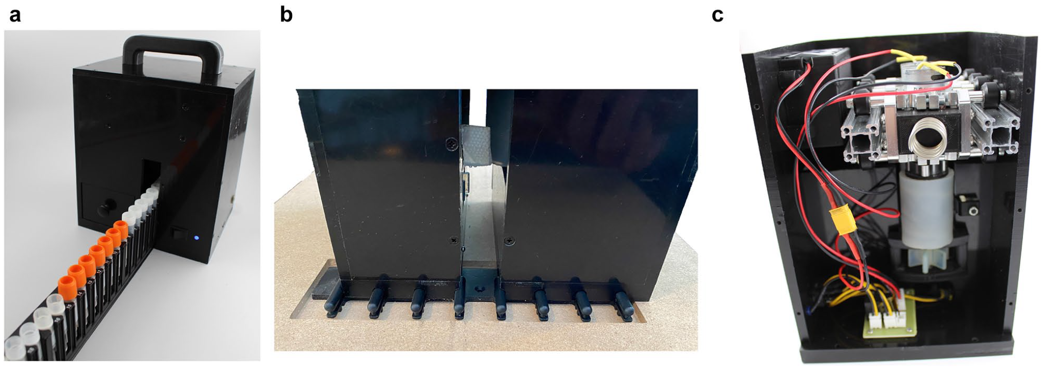
A rack of sample tubes moving through the uncapping device is shown in Figure 3a . A drawer shown in Figure 2a and Figure 3b is on the opposite side of the sprocket and collects sample tube caps as they are removed. An extended vertical wall within the device closes off the sprocket, ball-bearing switches (Metal Ball Tactile Button, 6 mm, cat. no. 3347, Adafruit, New York, NY), and other electronics from any possible contact with caps or their contents. Some caps sat on top of their respective tubes after they were unscrewed; for these, a peg that was 3D printed with flexible resin (Formlabs flexible resin, 80A Shore durometer), located near the device exit, directed them into the drawer, as shown in Figure 2a and Figure 3b . Ball-bearing switches are located at the bottom of the device and are activated when a sample tube rack is moved through the device, as shown in Figure 2a .
Electronics
The hardware block diagram of the device is shown in Figure 4 . A main power switch is connected to the nickel–metal hydride battery, and a light-emitting diode (LED) indicator is used to indicate whether the device is turned on. The two normally open ball-bearing switches are in parallel off the main switch and connected to the logic side of the relay, electrically isolating the switches. A 12 V nickel–metal hydride battery (Tenergy, Fremont, CA) with a capacity of 2000 milliamp hours 17 powered the motors. The two 12 V motors, in parallel, receive power from the normally open output of the relay. The motors run only when the main switch is activated and at least one of the ball-bearing switches is pressed by the rack.
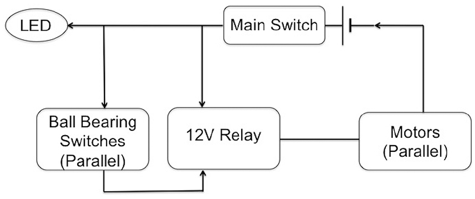
Block diagram for the electronic circuitry of the device.
Testing Protocols
Testing compared the uncapping speed of the device against the manual process currently used by technicians in commercial laboratories. The tests were conducted in a commercial laboratory, and actual technicians performed all tests. The success rate of the device in removing sample tube caps was quantified, as well as how consistently the caps were contained in the cap-catching drawer. It was important that the uncapping device achieved a high success rate and contained all the caps in the cap-catching drawer to prevent the technicians from manually intervening, introducing delays. Tests were also performed to determine the risk of contamination between sample tubes as they were uncapped using the device. Three different sample tubes were used for testing purposes: Tube A (3.5 mL, length = 6.6 cm, diameter = 1.15 cm, cat. no. 60.549.001, Sarstedt AG & Co. KG, Nümbrecht, Germany), Tube B (Corning 2 mL, length of vial with cap = 4.87 cm, diameter of cap = 1.37 cm, cat. no. 430659, Corning, Corning, NY), and Tube C (Fisherbrand 1.2 mL, length = 4.2 cm, outer diameter = 1.25 cm, cat. no. 12-567-500, ThermoFisherScientific, Waltham, MA). The following is a description of the methods used for each of these tests.
Efficiency Testing
To test if the device’s uncapping speed was faster than manual uncapping, the time required to fill and uncap one full rack of 32 sample tubes with the device (with n = 12) was recorded. The time required for the trained technicians (with n = 5) in the commercial testing laboratory to perform their standard workflow of uncapping 32 sample tubes and placing them into the rack was recorded. The data were analyzed using a one-sided t-test for unequal variances for p < 0.01 using Excel (Microsoft, Redmond, WA).
Success Rate Testing
Twelve total trials were repeated to test if the success rate while using the device was different than the success rate when manually uncapping racks of sample tubes. A full rack (32 sample tubes) was fed through the device, which constituted one trial, and the fraction of successfully uncapped tubes was recorded. Nine total trials, consisting of three trials for each of the sample tubes, were repeated for racks filled with each of the three commonly used sample tubes, labeled A, B, and C, as shown in Figure 1a . An additional three trials were completed with racks randomly filled with a variety of the three most commonly used sample tubes (A, B, and C). Since the manual procedure ensured that the sample tube caps were successfully removed, each trial was assumed 100% successful. The two groups of data were analyzed using a one-sided t-test for unequal variances in Excel. The test was deemed successful if there was no significant difference between the uncapping success rates of the device and manual procedures for p < 0.01. Fraction values were converted to percentages for easier comprehension.
Cap-Catching Test
The ability to easily collect caps after they were removed from the sample tubes was another feature incorporated into the device. To test this feature, the number of caps that successfully landed in the cap-catching drawer was recorded after the uncapping trials. This test was performed as a part of efficiency testing for n = 12 trials, each with a full rack of 32 sample tubes, for a total of 384 tubes and caps.
Contamination Testing
Contamination testing was performed using 64 sample tubes for each tube type. We filled the tubes with various amounts of either a blank matrix (human plasma) or blank matrix (human plasma) with Analyte-1 (moxifloxacin, USP, Rockville, MD) at 13 different known concentrations from 25 to 17500 ng/mL. The Analyte-1 was selected as a test compound due to the ready availability of analytical methodology that was applied to generate quantitative results used to evaluate the performance of the automated uncapping device. 18 It was used as a representative exogenous pharmaceutical drug compound, and the specifics of the molecule are not critical to the outcome of the experiments and the assessment of the utility of the uncapper device.
All sample tubes were frozen for more than 24 h and stored at −70 °C, and thawed for about 30 min to 1 h, like any samples received by the lab. Tubes were arranged in the rack in an alternating fashion between matrix and standard. The rack was sent through the device, and the tube contents were saved for analysis. A contamination threshold of 20% was determined, and mass spectrometry was used to determine % contamination. The % contamination is given as: % contamination = [(BLK MTX area count) / (CAL 1 average peak area)] × 100, where the mean value of CAL 1 is based on area counts of Analyte-1 peak obtained through mass spectrometry, and BLK MTX is blank matrix. Any contamination from the device procedure was evident by the presence of Analyte-1 in blank matrix sample tubes. This threshold is driven by the laboratory’s standard operating procedures (SOPs), which are in alignment with the US Food and Drug Administration’s (FDA) guidance for industry on bioanalytical method validation. 18
Results
Efficiency Testing
The average time taken for trained laboratory technicians to uncap one full rack of 32 tubes was 46.1 s (n = 5), while the device took 13.1 s ± 1.94 s (n = 12) (p < 0.01), indicating that using the uncapping device was significantly faster than the technicians manually uncapping racks of sample tubes.
Success Rate Testing
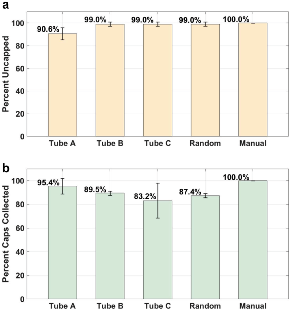
The average success rates for racks filled with sample tubes A, B, and C were 90.6% ± 5.41% (n = 3), 99.0% ± 1.81% (n = 3), and 99.0% ± 1.81% (n = 3), respectively, as shown in Figure 5a . Three racks were also filled with a random assortment of tube types, and these racks obtained an average success rate of 99.0% ± 1.81% (n = 3).
(
Cap-Catching Testing
The cap-catching performance for the different trials conducted is shown in Figure 5b . More than 80% of the caps were collected within the drawer using the cap-catching mechanism.
Contamination Testing
The maximum contamination for tube type A was 5.31%, tube type B was 3.16%, and tube type C was 1.57%. Overall, the maximum contamination in all batches was less than 6%, far lower than the necessary 20%. These results confirm that the device is a viable tool for bioanalytical laboratory testing operations.
Discussion
The uncapping device was significantly faster than when the technicians manually uncapped racks of sample tubes. The device was effective at uncapping more than 90% of the sample tubes, with little contamination. Moreover, the device demonstrated its potential to reduce or eliminate a significant source of repetitive motion. Repetitive and sustained hand exertions in laboratory tasks are considered important occupational risk factors associated with musculoskeletal disorders.5,19 The laboratory management reported that technicians sometimes process up to 700 sample tubes each day, with the repetitive task of opening and closing sample tubes of different sizes. Uncapping of the sample tubes is a major risk factor for repetitive-motion injury.
Several automated uncapping products that are currently on the market offer various effective solutions to significantly reduce the uncapping time, prevent occupational hazards, and enhance user safety. They may not, however, be easily integrated into the laboratory’s existing workflow. We designed a device for a potential customizable solution for such unique workflow situations that are unable to implement the current existing solutions. Our device, however, which is currently a prototype and in the development phase, presents the following limitations.
The device successfully uncapped sample tubes in three different diameters more than 90% of the time and took, on average, 13.1 s to uncap one full rack of 32 sample tubes. About 10% or less of the sample tubes left unopened were identified and manually opened, however. In addition, 20% or less of the unscrewed caps were not collected in the cap-catching drawer (shown in Fig. 2a ); they stayed on top of the sample tube or on the workbench, or in some cases were stuck between the rollers. These unscrewed caps were retrieved and thus added time to the uncapping process. These uncollected caps are also a source of contamination of the workspace, requiring additional time for thorough workbench cleanup, along with the cleaning or sterilization of the entire device for repeated usage. For sample tubes containing biological fluid or pathogens, such contamination issues are unacceptable and thus restrict the usage of the device for limited kinds of sample fluids. Similarly, the cross-contamination threshold was set to 20%, and the maximum contamination was observed as less than 6%. These threshold limits are acceptable for only certain bioanalytical laboratory testing operations; hence, it further limits the usage of the device to those laboratories. Thus, all of the above activities add additional time to the uncapping process and could result in more time needed to uncap the sample tubes than the manual method. Taking these drawbacks into consideration, additional testing is needed to accurately compare time benefits between the manual method and using our device to uncap sample tubes.
The average success rate with uncapping each of the three sample tube sizes, or a mix of them, was 90% or more. We observed, however, that tube type A, with the largest diameter of the three sample tubes, has the least success in getting uncapped, and we attributed this to the geometry and material of the sample tube caps, spacing between the rollers (see
Conclusions
The repetitive task of uncapping sample tubes increases the risk of musculoskeletal injuries. There are several commercial uncapping products that can automatically uncap sometimes upward of 96 sample tubes simultaneously, as presented in the Introduction section. There are challenges, however, with integrating these products into certain workflow environments, and they may also require sample tubes to have uniform caps and dimensions to function. Our current prototype can be easily implemented into the technicians’ workflow and can uncap a workload that uses a mix of tube sizes in three different diameters. The device’s uncapping times were more than three times faster than manual uncapping by the bioanalytical laboratory technicians. Additional time is lost, however, in identifying and de-capping the unopened caps, retrieving the uncollected caps, and also cleaning the resulting contaminated workbench and device. The technicians might optimize the efficiency of the device and further reduce the time required to uncap sample tube racks after becoming familiar with the product.
Although less effective than the manual method, the device was effective in uncapping more than 90% of sample tubes. Thus, it is assumed that the device could be successfully integrated into the technicians’ workflow pattern without significantly hindering the accuracy of their procedure. Furthermore, it is assumed that the technicians will manually remove any sample tube caps that are not successfully removed after passing through the uncapping device. Throughout the device testing, no noteworthy damage or loss of function occurred. Only minor wear of the rubber rollers was observed, which may be even further limited by selection of a material with greater wear resistance. From these results, we concluded that the device was durable and can withstand relatively heavy use. The outcome of each test proved the efficacy of the product. Thus, the device and its current performance still comprise a prototype that requires further development before it is usable for its intended setting, but it shows promise with the ergonomic benefit to laboratory technicians, reducing the necessity for manually unscrewing caps.
Supplemental Material
Supplemental_Material_for_Automated-Uncapper-Device_by_Jaeger,_et_al – Supplemental material for Automated Device for Uncapping Multiple-Size Bioanalytical Sample Tubes Designed to Reduce Technician Strain and Increase Productivity
Supplemental material, Supplemental_Material_for_Automated-Uncapper-Device_by_Jaeger,_et_al for Automated Device for Uncapping Multiple-Size Bioanalytical Sample Tubes Designed to Reduce Technician Strain and Increase Productivity by Jacob W. Jaeger, Scottland C. Adkins, Samuel C. Perez-Tamayo, Katelyn E. Werth, Gregory Hansen, Amit J. Nimunkar and Robert G. Radwin in SLAS Technology
Footnotes
Acknowledgements
The authors wish to thank Kelly Schepp and Sarah Pokwinski for help with contamination testing and insight into the problem at hand. The authors also thank the University of Wisconsin–Madison College of Engineering Team Lab staff for their invaluable assistance with the design and fabrication. This work was partially supported by Biomedical Engineering Design at the University of Wisconsin–Madison and by industrial gifts to the University of Wisconsin–Madison Tool Ergonomics Research Consortium.
Supplemental material is available online with this article.
Declaration of Conflicting Interests
The authors declared no potential conflicts of interest with respect to the research, authorship, and/or publication of this article.
Funding
The authors received no financial support for the research, authorship, and/or publication of this article.
References
Supplementary Material
Please find the following supplemental material available below.
For Open Access articles published under a Creative Commons License, all supplemental material carries the same license as the article it is associated with.
For non-Open Access articles published, all supplemental material carries a non-exclusive license, and permission requests for re-use of supplemental material or any part of supplemental material shall be sent directly to the copyright owner as specified in the copyright notice associated with the article.