
Abstract
Microplates are an essential tool used in laboratories for storing research materials and performing assays. Many types of laboratory automation exist that greatly reduce the effort needed to utilize microplates; however, there are cases where the use of such automation is not feasible or practical. In these instances, researchers must work in an environment where liquid handling operations are performed manually with handheld pipetting devices. This type of work is tedious and error-prone as it relies on researchers to manually track a significant amount of metadata, including transfer volumes, plate barcodes, well contents, and well locations. To address this challenge, we have developed an open-source, semiautomated benchtop system that facilitates manual pipetting using visual indicators. This device streamlines the process of identifying the location of wells so that the researcher can perform manual transfers in a more efficient, reliable, and accurate manner. This system utilizes a graphical user interface that allows the user to load worklists and then issues commands to illuminate wells of interest, providing a visual indicator for users to follow in real time. The software and hardware tools utilized for development, along with the implementation techniques used to produce this system, are described within.
Introduction
As an essential tool in research laboratories, microplates are commonly utilized for storage of chemical, biological, and physical samples, as well as a vessel in which assays can be executed. Microplates have been used since 1951, with manufacturing standards agreed upon by the Society of Biomolecular Screening (SBS; now SLAS) and approved by the American National Standards Institute in 2003.1,2 The adoption of these standards coincided with laboratory automation becoming more commonplace and has resulted in microplates becoming one of the most common types of labware used in modern laboratories.3–5 While modern automation supports many of the operations for which microplates can be utilized, there remain many use cases where scientists must still use handheld pipetting devices to manipulate microplates in a benchtop nonrobotic setting. Additionally, many efforts are underway to automate or semiautomate traditionally low-throughput laboratory tasks by leveraging open-source technologies to increase process efficiencies, reduce operating costs, and limit opportunities for error.6–9
For low-density plates, such as 24-well microplates, manual pipetting is a relatively straightforward task. However, pipetting into higher densities introduces challenges due to decreased well diameter and high well matrix density that increases the difficulty in locating specific wells, especially when many operations must be performed in a sequence. In these cases, manual pipetting is a laborious and error-prone task for which few attempts have been made to improve the user experience.10–14
To address this need, we have developed a system that acts as a semiautomated pipetting guide referred to internally as the Microplate Assistive Pipetting Light Emitter (M.A.P.L.E.). The system has been designed to be modular, able to support as many clear-bottom microplates as the user wishes to perform operations on. This is accomplished with a combination of custom electronics containing matrices of light-emitting diodes (LEDs) coupled with a graphical user interface (GUI) to provide a visual and interactive method for users to follow when a series of pipetting operations are to be undertaken. This GUI interface accepts user input in the form of worklists that define the plate metadata required for pipetting operations. At a minimum, these metadata include plate barcodes, well locations, and transfer volumes. We believe that the M.A.P.L.E. system offers advantages over previous light guide implementations in terms of both cost and functionality. For example, the EmbiTec LightOne Pro and Gilson Trackman Connected have list prices of $949 and $1400, respectively.12,14 These commercially available light guides also have limitations in terms of illuminating multiple microplates simultaneously for cherry-picking, limited LED colors available, and functionality restricted to built-in feature sets determined by the manufacturer. By contrast, the M.A.P.L.E. system is open source, modular, easily extensible to meet any user-desired feature, and relatively inexpensive, with prototype costs in the $100 range.
This pipetting light guide operates by parsing user worklists and translating the microplate metadata from each worklist into commands to turn on LEDs corresponding to wells identified for pipetting operations. As users complete individual pipetting operations, the GUI has “next” and “previous” buttons that allow the user to traverse the worklist. With each click of a “next” or “previous” button, commands are transmitted to the electronics to turn on LEDs corresponding to associated wells and turn off all other LEDs. Initial use cases for this system include manual cherry-picking where users are transferring samples from a source microplate to a destination microplate, and titration operations where an entire row or column of LEDs can be illuminated in sequence to help users track progress when performing serial dilutions within a single plate.
This system also attempts to address the ergonomics of lab bench pipetting. In benchtop pipetting, the microplate is typically placed on a flat surface and the user must position themselves over the plate in an awkward fashion in order to see the contents of the plate. Often, where the user needs to view the contents of a well, the user is required to pick the microplate up and hold it at an angle to inspect the wells of interest. The electronic components of the light guide that are used to illuminate individual wells are housed in a 3D printable enclosure that not only aligns the microplate above the LED matrix, but also tilts the microplate toward the user, enabling the user to inspect the contents of the plate while the plate is sitting on the benchtop.
Results and Discussion
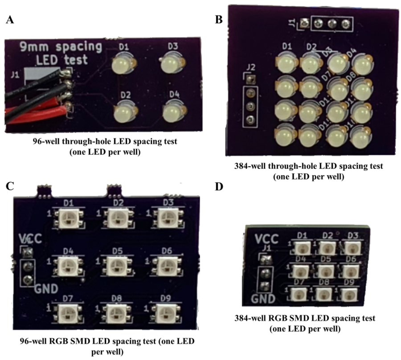
The initial concept for the light pipetting guide was to design an electronic circuit containing an LED matrix with a footprint that matched the SBS specification for microplate dimensions. The decision to use an LED matrix as opposed to an LCD screen with custom software was deemed preferable as the LEDs were more cost-effective, brighter, and required less complexity in both electronics and firmware to control. Each LED in the matrix would be aligned under the corresponding well of the microplate, allowing each well to be independently illuminated. This system provides users with a visual indication of where their pipettor should be placed to perform the desired operation. LED matrices are a commonly available consumer product and are produced in a wide variety of densities and pixel pitch spacings. For this design to work with one LED per well, the pixel pitch would need to be 9 mm for 96-well plates and 4.5 mm for 384-well plates, with the corresponding number of LEDs for each density. A 96-well plate requires an array containing 12 columns of LEDs with 8 rows, and the 384 array must be 24 columns by 16 rows. Unfortunately, off-the-shelf consumer LED matrix panels are sold with pixel pitches that do not match the SBS-defined well-to-well spacing of microplates. Further, most commercial LED matrix panels are designed with square profiles that contain matching numbers of rows and columns or as elongated rectangles with many more columns than rows, intended for scrolling text. Due to the pixel pitch and matrix size constraints, the decision was made to develop custom electronics with the LED matrix panels in the needed configurations.
Hardware
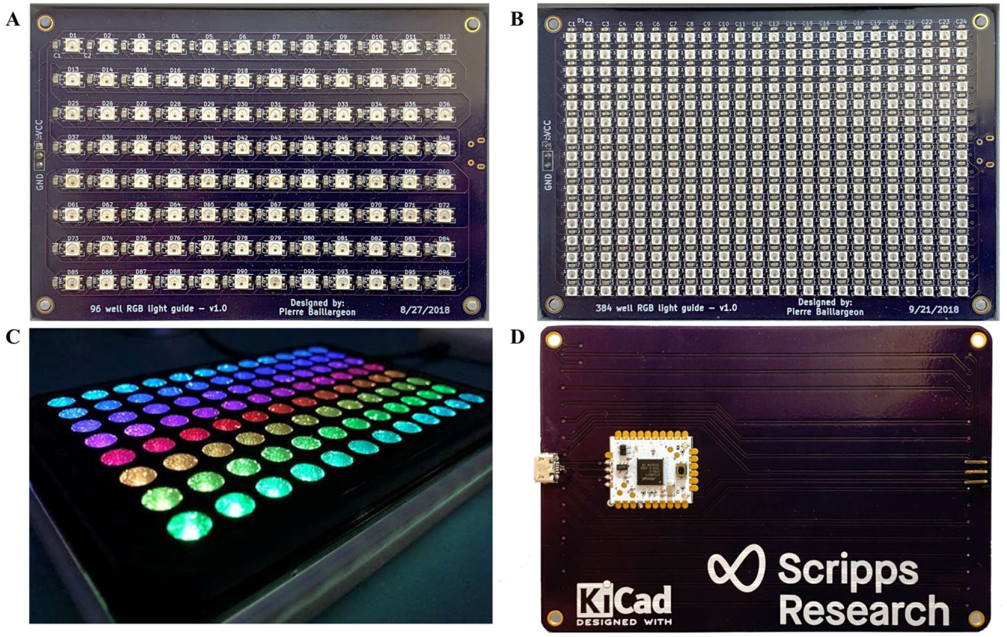
Two generations of prototypes were designed to prove the feasibility of this concept by creating smaller arrays of LEDs than would be needed to illuminate a full microplate, but with the correct pixel pitch. These initial prototype boards, seen in Figure 1 , were developed using KiCad, an open-source software suite for electronic design automation (EDA). 15 KiCad allows users to create schematics for electronic circuits and then to translate those schematics into printed circuit boards (PCBs) via PCB layout design tools. Additionally, KiCad documentation was available online that made translation of schematics into PCBs fairly straightforward.16–18 At each stage of design and testing, the design files were sent for manufacturing using OSH Park’s PCB fabrication pooling service, which allows small quantities of PCBs to be produced rapidly at low cost. 19
(
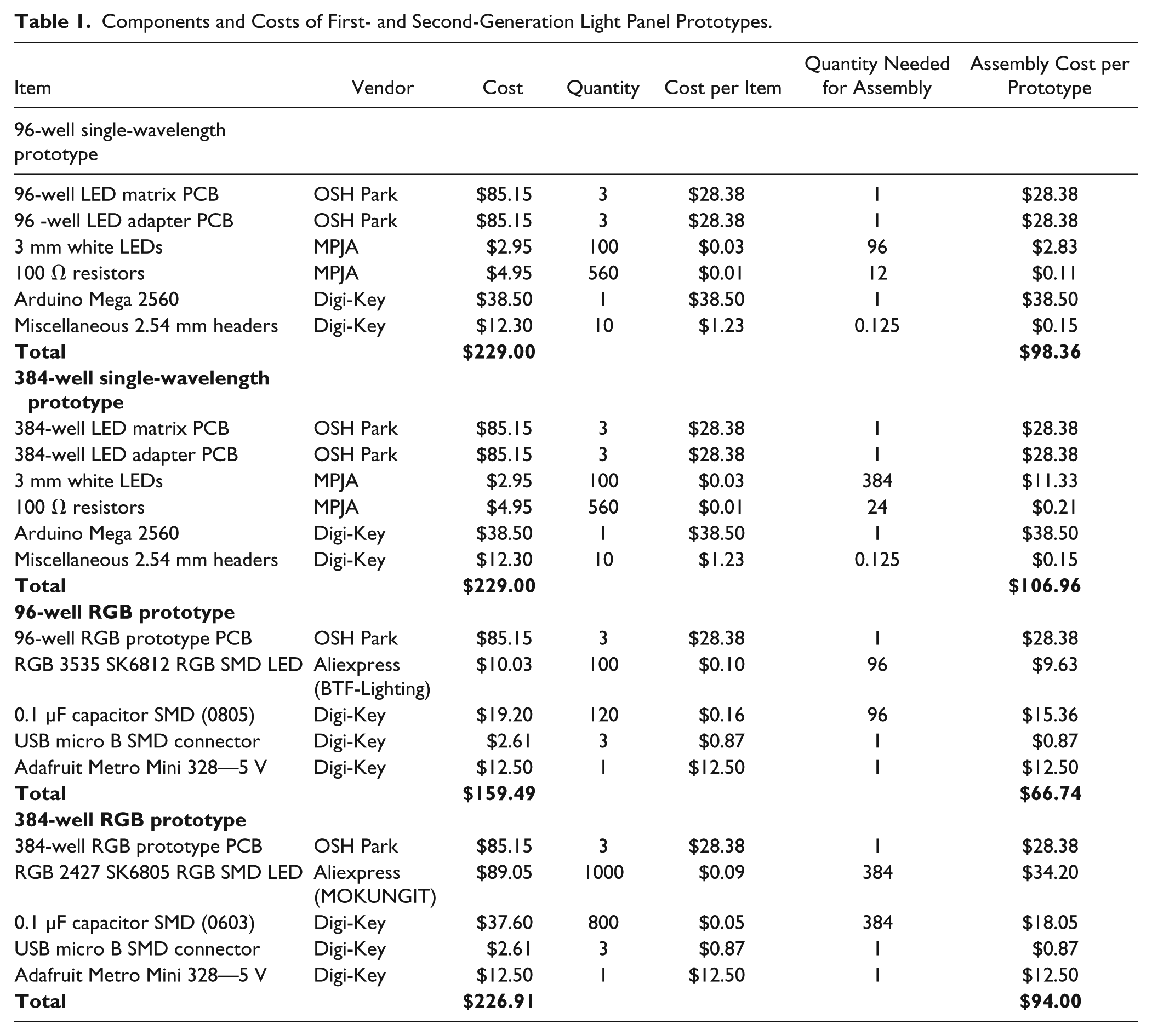
The first-generation design utilized 3 mm white diffused LEDs in a common-row anode layout and were sourced from Marlin P. Jones & Associates, Inc. (West Palm Beach, FL). 20 Second-generation boards were also designed to explore alternate LED component types that provide multicolor indication with single wire control, utilizing SK6812 red–green–blue (RGB) surface-mount device (SMD) LEDs for 96-well format and SK6805 RGB SMD LEDs for 384-well format. The SK6812 and SK6805 RGB LEDs were sourced from BTF-LIGHTING (Shenzhen, China) and MOKUNGIT (Shenzhen, China) stores on AliExpress, 21 respectively. In addition to enabling a wide range of colors to be displayed, the SK series of RGB LEDs integrate a control circuit into the LED package, allowing multiple LEDs to be controlled in series with a single I/O line that simplifies the electronics design. Costs for the finished prototypes ranged from $70 each to $107 each, as seen in Table 1 .
Components and Costs of First- and Second-Generation Light Panel Prototypes.
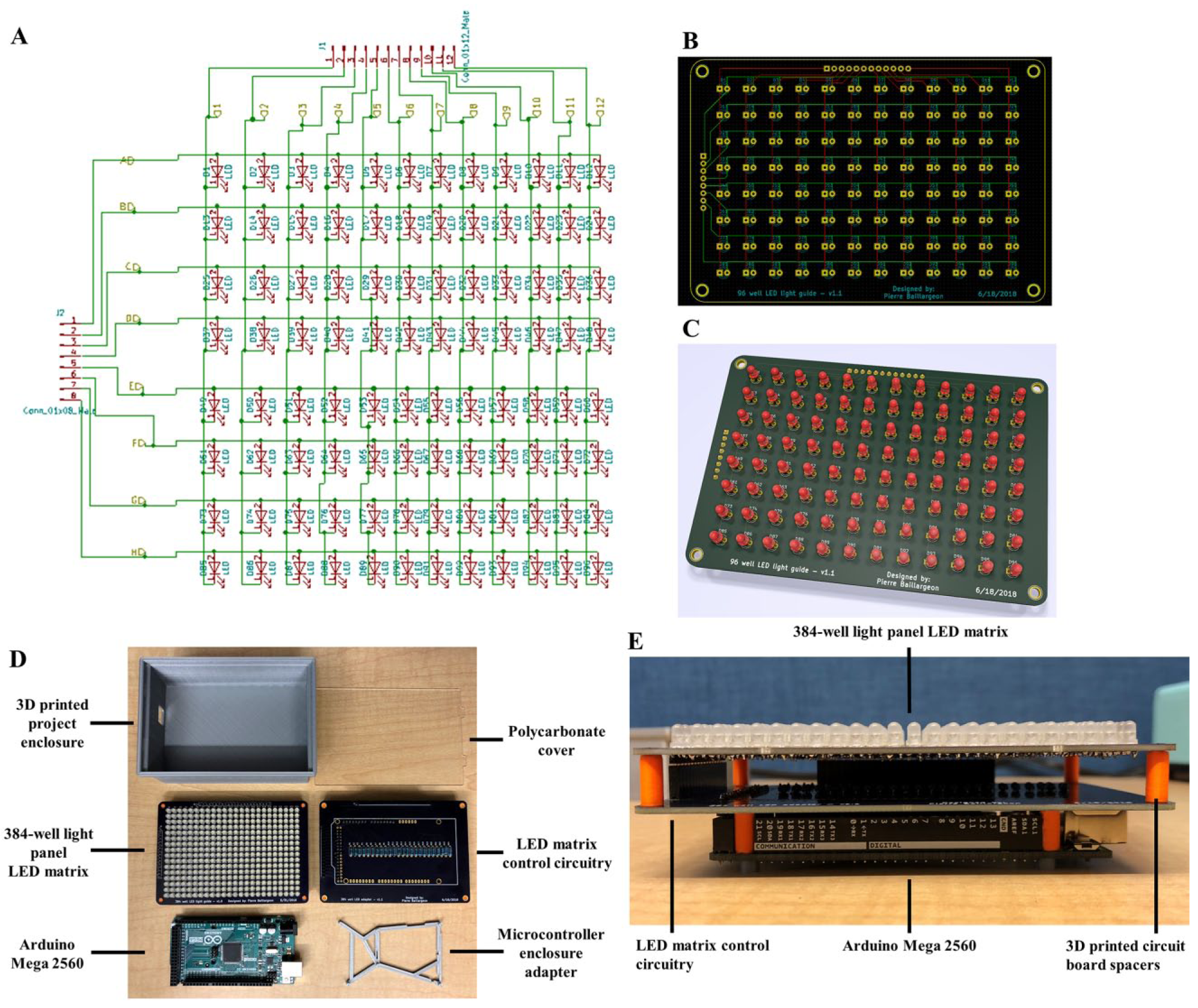
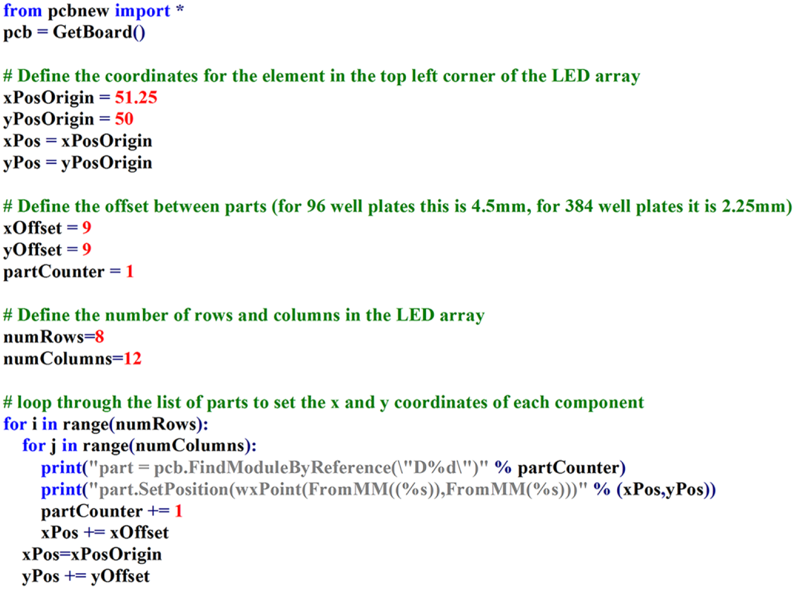
Once the function and spacing constraints were verified, the designs were scaled up to full size and prototypes were produced as seen in Figure 2 . One feature of KiCad that assisted in this process was the ability to programmatically control component locations on the PCB using Python. The example code shown in Figure 3 demonstrates how the X and Y coordinates of 96 LEDs could be easily set on the final PCB design using a few lines of Python. With this functionality, PCB components can easily be arranged into any orientation and alignment, resulting in significant time savings to complete final PCB designs.
(
Python code used to arrange LEDs in a 12 × 8 matrix for a 96-well illumination panel with one LED per well.
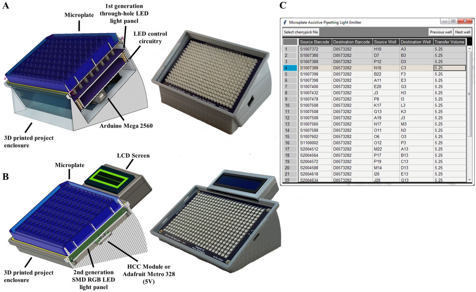
The first-generation boards were designed to function as a two-part Arduino shield that would plug into an Arduino Mega 2560 microcontroller (
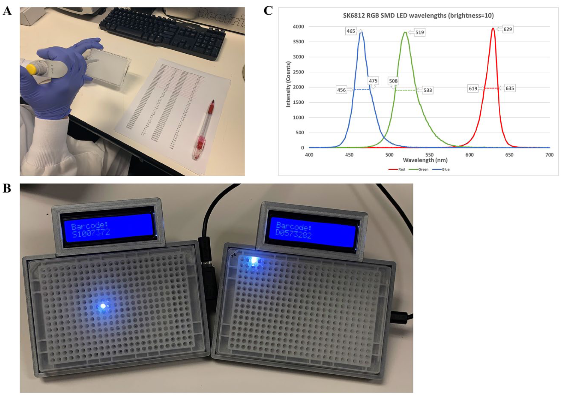
The second-generation boards ( Fig. 4 ) utilized SMD LEDs, which allowed a greater number of components in the same PCB footprint size. The decision was made to keep all components on a single board, including space for an Arduino-compatible surface-mount programmable microcontroller called the HCC Module ( Fig. 4D ). 22 In place of the HCC Module, any 5 V microcontroller can also be used, and early prototypes made use of the Adafruit Metro Mini 328 microcontroller. 23 For prototype assembly, the second-generation PCBs also required SMD solder paste stencils to apply solder paste to the prototype PCBs and were ordered via OSH Stencil. 24 Benefits of the second-generation design include greatly reduced I/O requirements, automation of PCB assembly due to use of SMD components, thinner device profile, software-controllable LED brightness levels, and full RGB color display capabilities from each LED ( Fig. 6C ). The second-generation design also incorporated a 2-row by 16-character Adafruit backlit LCD display with an i2c/SPI character LCD backpack to allow plate metadata to be displayed to the user during pipetting operations.25,26 The addition of the LCD allows users to quickly verify that the correct source and destination plates are in use.
(
For both first- and second-generation designs, project enclosures were designed in Autodesk Fusion 360 and fabricated in-house using an Ultimaker 2+ 3D printer. Three-dimensional PCB models were exported from KiCad in STEP file format in the Pcbnew Layout Tool and subsequently imported into Fusion 360 for use as a reference while designing project enclosures.
27
With the PCB models imported into Fusion 360, project enclosures could easily be modeled and then 3D printed (
(
Software
The firmware needed to drive the LEDs and associated electronics was implemented using the Arduino IDE. A command set was defined that would allow the Arduino firmware to communicate with external control programs via a USB serial connection. This command set is defined with the following format: <row, column, command>. The row parameter accepts alpha characters representing the plate row, while the column parameter accepts numeric characters representing the plate column. The command parameter is defined to accept the following alpha characters: S—illuminate a single well, R—illuminate an entire row, C—illuminate an entire column, X—turn all LEDs off. For the R or C commands where only the row or column needs to be specified, the firmware simply ignores the value assigned to the unneeded parameter when called. Examples of valid commands include <B,7,S>—illuminate well B7, <B,7,R>—illuminate row B, <B,7,C>—illuminate column 7, <B,7,X>—turn off all LEDs. The second-generation firmware uses a slightly modified command set in the format <row, column, command, barcode>, which allows the plate barcode to be transmitted for display on the included LCD screen.
To communicate with the Arduino, a Python program was developed with a graphical interface ( Fig. 5C ) that accepts user-created worklists in comma separated value (CSV) text files. The GUI interface for the Python program was developed using the tkinter library to provide a user-friendly method for interacting with the light guides. For the hitpicking function of the software, the format of the text file is as follows: Source Barcode, Destination Barcode, Source Well, Destination Well, Transfer Volume. When a user specifies a worklist file through the GUI interface by clicking the “Select cherrypick file” button, the Python program utilizes the pandastable library to store the contents of the CSV into a dataframe. The contents of this dataframe are then displayed to the user in a format visually similar to Microsoft Excel. The Python GUI then transmits the first records of the dataframe to the connected Arduino microcontrollers via USB serial port to turn on the LEDs that correspond to the first well locations ( Fig. 6 ). For a typical hitpick operation, this means that the GUI interface has transmitted two separate commands for each row in the hitpicking worksheet: one command to the source microplate light panel to illuminate the target well of the light guide with the source microplate, and a second command to the destination microplate light panel to illuminate the corresponding well in the destination microplate. The GUI highlights the active row to allow the user to track which plates are needed for each operation by plate barcode, along with the transfer volume requested for the current pipetting operation. At any time, a user can click the “Select cherrypick file” to load a new worklist or close the program to turn the illumination panels off.
(
The development of these light guides has demonstrated the capabilities of open-source software tools and the impact that they can have in rapidly developing custom software and hardware automation for laboratory use. This system has now been tested within the Scripps Screening Center laboratories and found to be reliable, robust, and user-friendly. Its cost of manufacturing and implementation is minimal and its advantages to users far exceed such. Future applications include utilizing the light panels to investigate microplate-based photochemistry, detecting fluorescent interference compounds (absorbers for excitation/emission), and developing absorbance-based microplate readers. The functionality of the light guide could also be extended by adding barcode readers to the project enclosures to ensure that users have the correct microplates for each pipetting operation, and by adding support for a foot pedal to enable hands-free control of next well/previous well selection in the Python GUI. The second-generation light guide firmware could easily be extended to allow the LED color and brightness to be user- or sensor-controllable to automatically adjust for ambient light or to accommodate for the unique light diffusion characteristics of various microplates. The second-generation enclosure could also be modified to allow for user control of the tilt angle via thumbscrews and a pivot joint, allowing users to set their preferred viewing angle. The project enclosures used for the light guide electronics may also be of interest to laboratory users as a simple ergonomic aid as a stand-alone item without the light guide.
We have published all materials needed to reproduce this project on GitHub, including the Arduino Firmware, Python GUI, KiCad PCB design files, and Fusion 360 3D printable project enclosures: https://github.com/pierrebaillargeon/Microplate-Assistive-Pipetting-Light-Emitter.
Footnotes
Declaration of Conflicting Interests
The authors declared no potential conflicts of interest with respect to the research, authorship, and/or publication of this article.
Funding
The authors received no financial support for the research, authorship, and/or publication of this article.