
Abstract
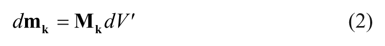
Mechanical properties of the extracellular matrix (ECM) have been observed to influence the behavior of cells. Investigations on such an influence commonly rely on using soluble cues to alter the global intrinsic ECM properties in order to study the subsequent response of cells. This article presents an electromagnetic system for inducing a localized force gradient in an ECM, and reports the experimentally observed effect of such a force gradient on in vitro angiogenic sprouting of human microvascular endothelial cells (HMVECs). This force gradient is realized through the induction of magnetic forces on the superparamagnetic microparticle–embedded ECM (sECM). Both analytical and statistically meaningful experimental results demonstrate the effectiveness of this approach in influencing the behavior of a targeted HMVEC sprout without affecting that of other sprouts nearby. These results suggest the possibility of selectively controlling the in vitro behavior of cells by the induction of a localized force gradient in the ECM.
Introduction
Mechanical manipulation of biological material has been attracting increasing interest from the field of mechanobiology. This is because it may offer vital information on how mechanical stimuli influence a multitude of biological processes, ranging from cell growth to organ development. 1 Among the established techniques (e.g., optical tweezers 2 and atomic force microscopy 3 ) for exerting forces onto biological entities, magnetic manipulation has received particular attention since its first demonstration in characterizing the physical properties of a cytoplasm, as it is capable of applying reconfigurable forces and torques. 4 Furthermore, studies have also shown that cell exposure to static magnetic fields alone has no effect on cell growth and genetic toxicity, regardless of the magnetic density.5,6 The magnetic method is based on noninvasive manipulation of magnetic particles, where particles are typically attached to or embedded in the biological entity, and forces are induced by imposing a magnetic field gradient. This technique has been widely utilized as a biophysical tool to study cell mechanics and mechanotransduction. However, those studies mainly focus on how physical forces and changes in the mechanical properties of cells and tissues contribute to development, physiology, and disease. In fact, cell–matrix mechanical interactions also play a defining role in a gamut of biological processes.
Advances in mechanobiology have suggested that in vitro cellular responses may be influenced by the mechanical properties of the extracellular matrix (ECM) in general, and ECM stiffness in particular. The ECM stiffness is noted to modulate cell signaling broadly, with effects on motility, survival, and growth.7,8 While the optimum stiffness for different cell types varies widely, it is generally observed that a more rigid matrix promotes cell spreading and focal adhesion formation.9,10 Cell motility and polarity have also been examined to have some correlation with the matrix stiffness; that is, cells prefer to migrate up rigidity gradients (in the direction of greater stiffness). 11 Understanding the underlying mechanisms of how the changes in ECM stiffness, along with the physiological and pathological conditions, is important could have significant implications on the advancement of cancer therapies,12,13 tissue engineering,14,15 and drug screening. 16 Various methods have been proposed to alter the stiffness of ECM, such as by varying the collagen concentration, 17 the pH value, 18 and the polymerization temperature. 19 These reported approaches change the global intrinsic material properties of the ECM permanently (i.e., the change in the ECM stiffness is irreversible) and are assumed to remain constant after modification. However, most in vivo ECMs have material properties that change dynamically. Furthermore, those approaches mainly employ soluble cues (such as by changing the pH value), which causes inconsistencies in the chemical composition of the matrix when evaluating the cellular behaviors under different ECM stiffness conditions. Magnetic manipulation may offer a viable alternative for addressing these issues.
Recent results20–22 have demonstrated that ECM stiffness can be altered by mechanically manipulating the deformability of the collagen fibers in the ECM through magnetic manipulation. The proposed approach works by embedding magnetic particles in the ECM through bioconjugation with the collagen fibers and then employing a magnetic field gradient to exert forces on the particles. These works quantified and analyzed the changes in the deformation and the apparent stiffness of the particle-embedded ECM under the influence of the magnetic field. It is observed that the ECM deforms in the direction of the magnetic field gradient, consequently altering the apparent stiffness of the ECM.
In the work reported in Chen et al. 23 and Herath et al., 24 a magnetomicrofluidic system (based on the approach of Herath and coworkers20–22) was developed to study the regulation of the ECM stiffness gradient on human microvascular endothelial cell (HMVEC) sprouting. The system uses cuboid permanent magnets (whose magnetic field spreads widely) to induce static forces at the sites in the ECM occupied by the magnetic particles. It was found in the reported experiment that the nonlocalized magnetic forces affected all the sprouts in the microfluidic device used in the experiment. This renders the system unsuitable for investigating the responses of selected sprouts in the device to the applied stimulus without affecting the rest of the sprouts. The aim of this current work was to apply the same approach as reported in our earlier work20 –22 to mechanically manipulate the ECM in order to demonstrate the effect of such localized manipulation on in vitro angiogenic sprouting of HMVECs at a phenomenological level.
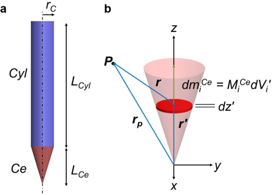
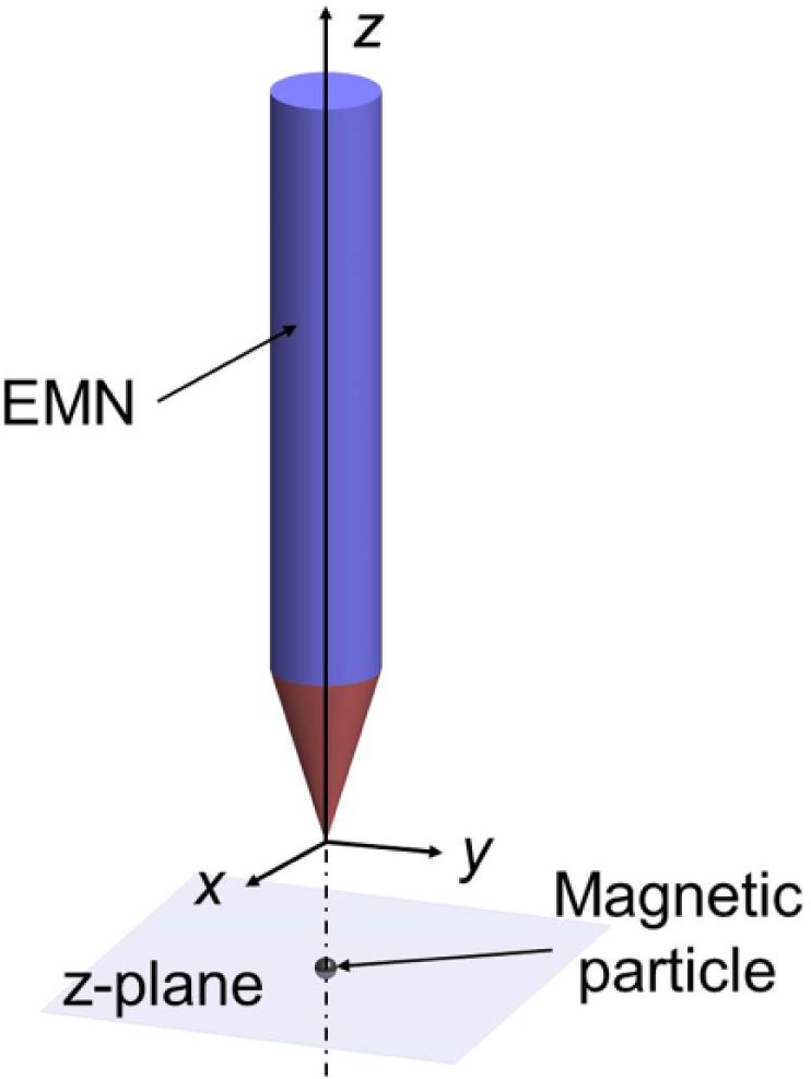
In this article, we propose a new approach to introducing a localized mechanical stimulus in the form of a magnetic force gradient (in a superparamagnetic particle-embedded ECM) that can potentially influence the behavior of a targeted HMVEC sprout without affecting that of other sprouts nearby. We used an electromagnetic needle (EMN) to induce a localized force gradient in a three-dimensional ECM, and studied the experimentally observed effects of such a stimulus on the in vitro angiogenic sprouting of HMVECs. The EMN consists of a solenoid wrapped around a soft magnetic core. The core is made of high magnetic permeability/saturation material to produce a large magnetic field gradient. The design of the core (as illustrated in Fig. 1a ) is represented by an axially symmetrical cylindrical shank (i.e., Cyl, shaded in blue) with a protruding conical tip (i.e., Ce, shaded in red). The tip geometry is designed to concentrate the magnetic flux toward the area of interest on the ECM in order to generate localized forces. With the characterized EMN, we applied the magnetic technique to the ECM. Superparamagnetic particles were embedded in a three-dimensional ECM through bioconjugation (between the streptavidin-coated particles and collagen fibers). We refer to such a particle-embedded ECM as sECM. HMVECs were allowed to form sprouts in the sECM and were conditioned with a vascular endothelial growth factor (VEGF) gradient for 4 days. On the fourth day, the EMN was introduced to continually exert localized forces (which were aligned with the direction of sprout elongation) on the anterior region of a targeted sprout tip for 5 h. The sprouting behavior of the HMVECs was observed under a confocal microscope and quantified in terms of the height of the sprouts, which reflected the extent of sprouting at the cellular level.
(
The remainder of this article is organized as follows. The “Magnetic Induction Modeling” section describes and validates the analytical model of the EMN for determining the magnetic fields and forces. The “Induction of a Localized Force Gradient in an ECM” section describes the design and implementation of the experiments for inducing a localized force gradient in an ECM, and it also presents the experimental results. Finally, the “Summary and Discussion” section summarizes the article and discusses the results from the experiments.
Magnetic Induction Modeling
Magnetic Fielding Modeling
We based our analytical model for calculating the magnetic field produced by an EMN on a system of magnetic dipoles.25,26
The magnetic field of the EMN at any given point in the workspace
Hence, the associated magnetic field at
where m0 = 4p × 10–7 Tm/A is the magnetic constant.
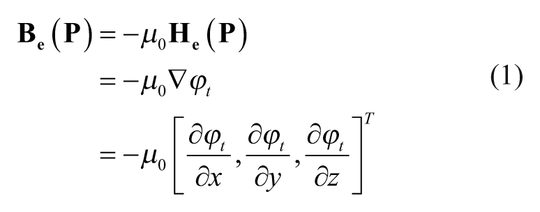
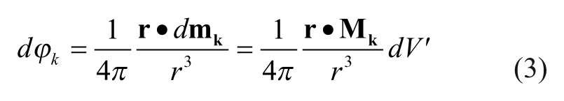
An elementary magnetic dipole with a volume of dV′ and a magnetization
which creates an elementary magnetic scalar potential
where
The magnetic core is represented by two parts: (1) Ce and (2) Cyl. The geometry of the core, together with the solenoid encompassing Cyl, dictates that the dominant component of the core magnetization aligns with its longitudinal axis (i.e., z′– axis), and therefore
The overall magnetic scalar potential
As the scalar potentials decay rapidly with
where Msat refers to the saturated magnetization of the material, and factor a is related to the other physical properties. 27
If the EMN is orientated or translated, the magnetic field
Experimental Validation of Magnetic Field
Experimental Setting
We positioned an EMN in the configuration, as illustrated in Figure 2 , to investigate the validity of the magnetic field model. This configuration serves to establish a common basis for comparing the results from the model, and the experiments. The fabricated EMN has a magnetic core of 69 mm cylindrical length (with a radius of 6.35 mm) and a conical height of 21 mm, terminating with a tip radius of 33.25 µm. The core is made of a soft magnetic material (i.e., hysteretic effects are negligible) with a magnetization curve as reported in Figure 3 . This curve is experimentally obtained using a vibrating sample magnetometer (Model 7407, Lake Shore Cryotronics, Inc., Westerville, OH).
Configuration of the EMN for model validation.
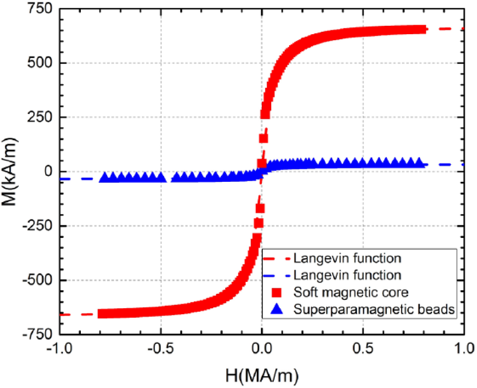
Magnetization curves of the soft magnetic core (red) and the 3.02 µm superparamagnetic particles (blue).
The experimental characterization of the EMN is achieved using a gauss meter equipped with a hall sensor probe (Model GM07, Hirst Magnetic Instruments Ltd., Cornwall, UK). The probe measures the magnetic field component that is perpendicular to its sensing element. The EMN is mounted on a three-axis motor-driven positioning stage. The stage, with a travel range of 100 mm in all directions with a step resolution of 2 µm, is used to precisely control the relative distance between the EMN tip and the hall sensor probe.
Experiment Procedure
Six sets of experiments were conducted to measure Bez (z), with each set corresponding to an input current of 0.1, 0.25, 0.5, 1, 2, and 3 A. The hall sensor probe is placed directly 0.2 mm underneath the EMN tip, to prevent possible collision damage. For every individual experiment, the EMN is shifted along the z–axis (away from the probe) from 0.2 to 2 mm with an increment of 0.1 mm. Due to the axial symmetry of the EMN, Bez (y) is equal to Bez (x), and Bey (y) is equal to Bex (x). Similar experiments are repeated for Bez (y) and Bey (y), with the EMN shifted along the y– axis from −1 to 1 mm with an increment of 0.1 mm.
Experimental Results
We found that there were discrepancies between the measured and computed results. Nevertheless, by introducing a multiplicative scaling function of
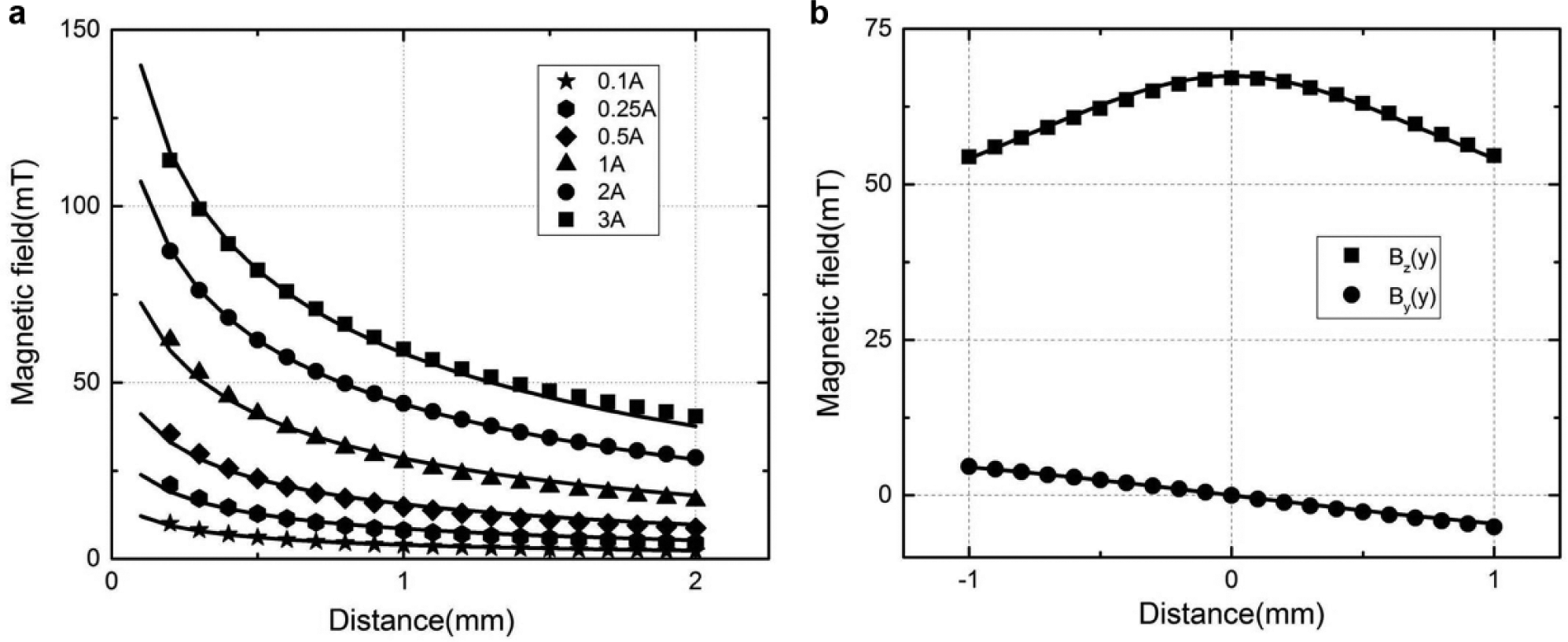
Comparison of the predicted and experimentally evaluated magnetic fields. (
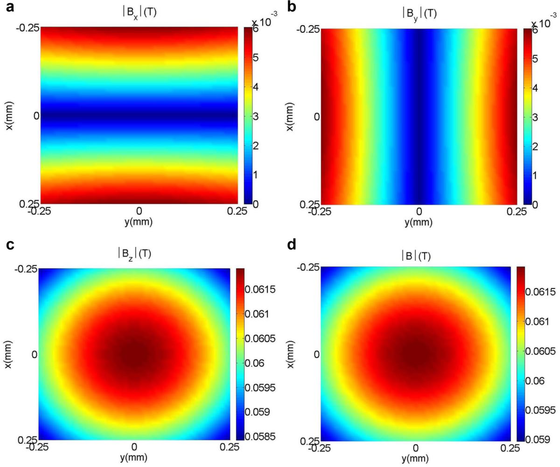
Mapping of the magnetic field (
Magnetic Force Modeling
The orientation and position of a magnetic particle can be manipulated by controlling the induced magnetic force and torque. With a soft magnetic particle (i.e., superparamagnetic particles) where hysteretic effects are negligible, the magnetic moment is dependent on the applied field, and its magnitude varies with changes in the field. For the manipulation of spherical particles, the geometry warrants special mention. This is because there is no shape anisotropy, and therefore the magnetization vector will always align itself with the induced field. Consequently, no torque will be generated on the particle.
28
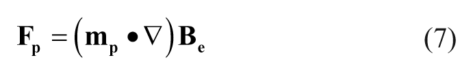
The force that the spatial gradient of the magnetic field exerts on the magnetic moment
Since there is no electric current flowing through the region occupied by the particle, Maxwell’s equation provides the constraint
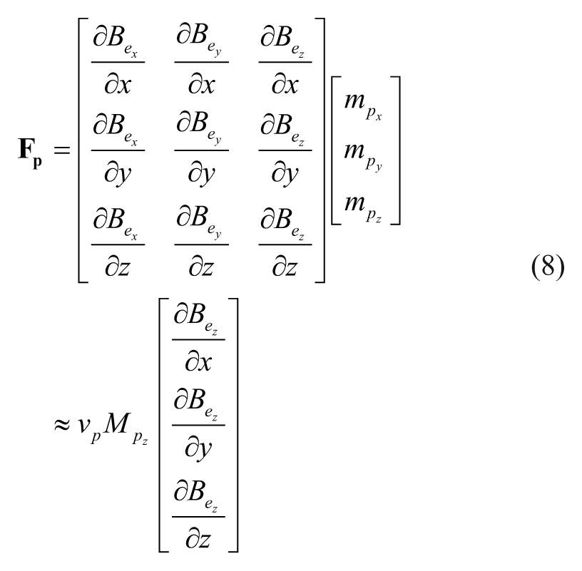
where
With the quantitative agreement between the predicted and experimentally evaluated magnetic fields, we can now use eq 8 to compute the forces exerted on a magnetic particle. For the investigation of the validity of the magnetic force model, we arranged an EMN in the configuration shown in
Figure 2
, where the magnetic particle is positioned directly underneath the EMN tip (i.e.,
The magnetic forces in the z –direction
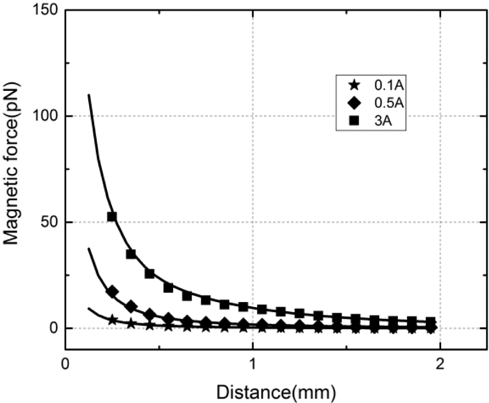
Comparison of the predicted and experimentally evaluated magnetic force Fpz at various distances (between the particle and EMN tip distances) with input current varying from 0.1 to 3 A. Data points are values evaluated with the measurements from the hall sensor probe. Solid lines are the calculated values from the analytical model.
Ideally, an inverse force model will enable convenient determination of required inputs to the EMN to produce the desired magnetic forces. Such an inverse model is particularly desirable for force spectroscopy application (such as single-molecule stretching31–33), where typically we are interested in the single-axis force applied normal to the region of interest. Force–distance curves for multiple currents are calculated, and a simple mathematical expression is fitted to the variables of distances D, forces F, and input currents I. Equation 9 describes this nonlinear relationship, using four fitting parameters. With this equation, forces at any measured distances and input currents can be accurately described.
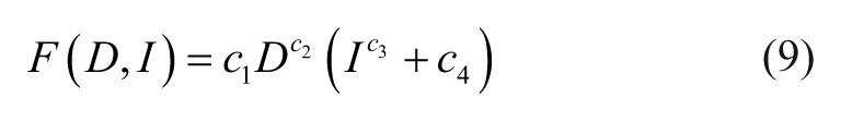
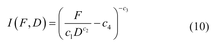
Alternatively, eq 9 can be rearranged to compute the necessary driving current (i.e., eq 10) or EMN position (i.e., eq 11) to generate the desired forces.
Induction of a Localized Force Gradient in an ECM
Experiment Design
With the fully characterized EMN, we applied the magnetic micromanipulation technique to induce a localized force gradient in a three-dimensional sECM. The effects of the induced mechanical stimulus (in the form of a localized force gradient) are studied on in vitro angiogenic sprouting of HMVECs in a microfluidic device. The features of the microfluidic device are provided in Figure 7 . There are 37 slots in each device, and each slot spans the region between two trapezoidal-shaped posts, where angiogenic sprouting of the HMVECs takes place. HMVECs were allowed to form sprouts in the sECM and were conditioned with a VEGF gradient for 4 days. On the fourth day, the EMN will be introduced to induce a localized magnetic force gradient at the anterior area of a targeted slot (where the HMVEC sprout forms) for 5 h. The EMN is orientated to ensure that the forces experienced by the magnetic particles embedded in the ECM are aligned with the direction of the sprout elongation. The sprouting behavior of the HMVECs is observed under a confocal microscope and quantified in terms of the height of the sprouts, which reflect the extent of sprouting at the cellular level.
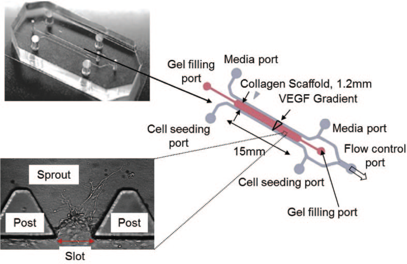
Features of the microfluidic device.
Experimental Setup
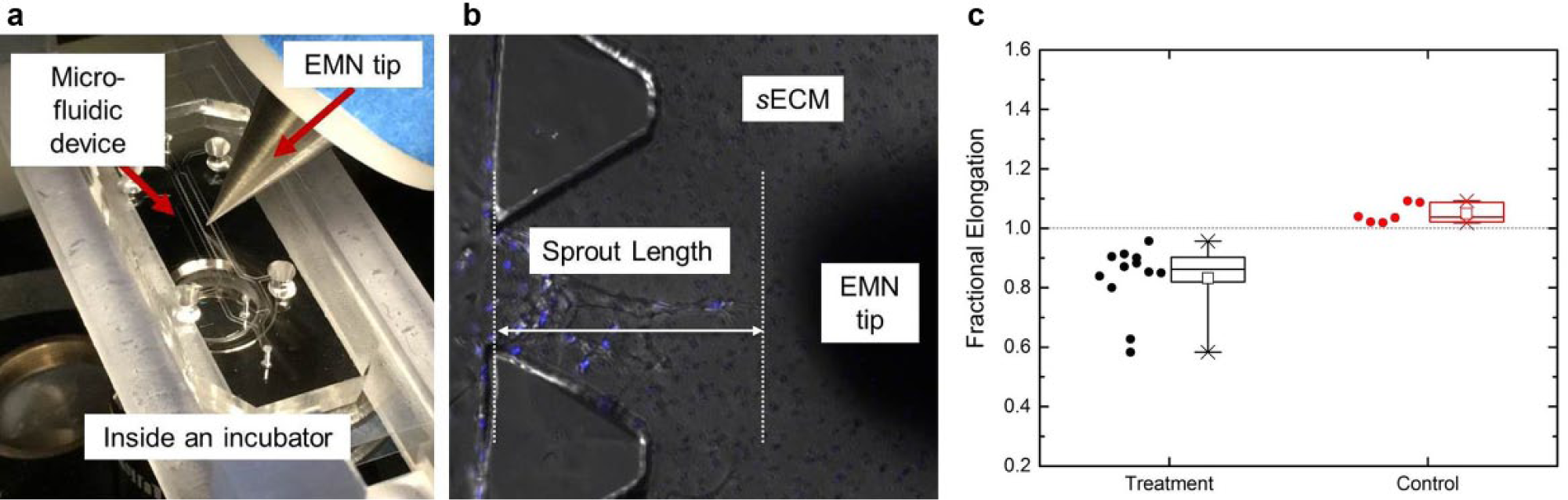
The experimental setup is shown in Figure 8a . The EMN setup is placed within the incubator of a confocal microscope (Olympus FV1200). The EMN is orientated at an angle of 50° with respect to the horizontal plane (to avoid obstructing the light source and microscope lens) by a custom-made holder mounted on a three-axis high-precision positioning stage. The stage, with a travel range of 4 mm in all directions with a step resolution of 50 nm, is used to precisely control the EMN tip close to the targeted sprout. The custom-made holder has an aluminum body with brass fasteners, both having a relative permeability of 1 (i.e., the same as that of free space). This means that the holder neither responds to the surrounding magnetic field nor influences the magnetic interaction between the EMN and the sECM. Furthermore, this holder also acts as an excellent heat sink since aluminum has a high thermal conductivity, and this allows rapid dissipation of any possible heat generated by the EMN.
(
In order to exclude the possible thermal effects generated by the EMN on HMVEC sprouting, an experiment was conducted to examine the temperature change in the sECM. The experiment involved two of type T thermocouples to measure the surface temperature of the glass coverslip, specifically the surface that is in contact with the sECM (where the HMVEC sprout forms). The sensors were attached onto the glass surface and were positioned with a lateral separation of 2.5 mm. For the acquisition of the temperature readings, the sensors were connected to a data acquisition device (National Instruments, Austin, TX, NI 9211) and a LabVIEW program was implemented to facilitate the measurements. The EMN is positioned on the other side of the coverslip and above one of the sensors. This experiment setting is to simulate the actual experiment with the HMVECs, in which the EMN tip and the sECM are separated with a coverslip. We refer to the sensor that is placed below the EMN tip as sensor A and the other as sensor B. For the experiment, the EMN is switched on for 5 h. The before and after of the surface temperature acquired by sensor A revealed that there is a change of 0.193 °C, and the temperature across the coverslip (i.e., the temperature difference between sensors A and B) is 0.181 °C. These experimental results suggest that the heat produced by the EMN is negligible and should not significantly affect the HMVEC sprouting in the sECM. Even if there is a thermal effect, both sprouts in the targeted and adjacent slots (which are spaced apart by the trapezoidal-shaped post) would be affected by similar heat effects. These results are also in alignment with the application setting of various prior works34 –37 involving magnetic micromanipulation.
Experiment Protocol
Streptavidin-coated superparamagnetic particles (i.e., the same magnetic particles discussed in the “Magnetic Force Modeling” section) were embedded into the ECM before polymerization through bioconjugation (between the particles and the collagen fibers). This collagen–particles solution was then injected into the gel filling channel of the microfluidic device. The HMVECs were delivered to the device through the cell seeding channel, and cells were allowed to form a confluent monolayer prior to conditioning. They were conditioned with VEGF at 20 ng/mL in the cell seeding channel and at 40 ng/mL in the media channel for 4 days, and the HMVEC sprouting took place at the slots of the device. The details of the preparation of the microfluidic devices, sECM, and HMVECs are included in Appendix B. On the fourth day, cells in the device were stained with Hoechst (blue) and propidium iodide (red) 30 min before the experiment. The purpose of staining the cells was to identify apoptosis signals during the experiments and exclude false-positive errors.
Twelve sets of experiments were conducted in an incubator, and the cells were kept in a humidified, 5% CO2, and 37 °C environment. For every individual experiment, images of the device were obtained hourly using the confocal microscope. Each experiment was carried out by observing the sprouting behavior of a targeted HMVEC sprout (identified by a height of >100 µm) in the microfluidic device for 5 h, where the EMN applies the localized force gradient in the sECM. The EMN (with an input current of 3 A) continually exerts forces on the anterior region of the targeted sprout tip (at a distance approximately 70 µm away). The images obtained from the confocal microscope were then analyzed using Imaris.
Experimental Results
We refer to the scenario of having the force gradient applied at a targeted slot as the treatment and the slot adjacent to the targeted sprout as the control. For the quantification of endothelial sprouts, time-lapse analysis is done using Imaris on the images acquired from the experiments. Figure 8b illustrates our measurement of the sprout heights, that is, the vertical difference from the sprout tip to the bottom of the trapezoidal-shaped posts. The sprout heights are measured before and after the experiments, and the results from the 12 sets of experiments are presented in Figure 8c , that is, Fractional elongation = Final sprout height/Initial sprout height. The statistical results are shown in Table 1 .
Statistics of the HMVEC Sprouting Experimental Results.
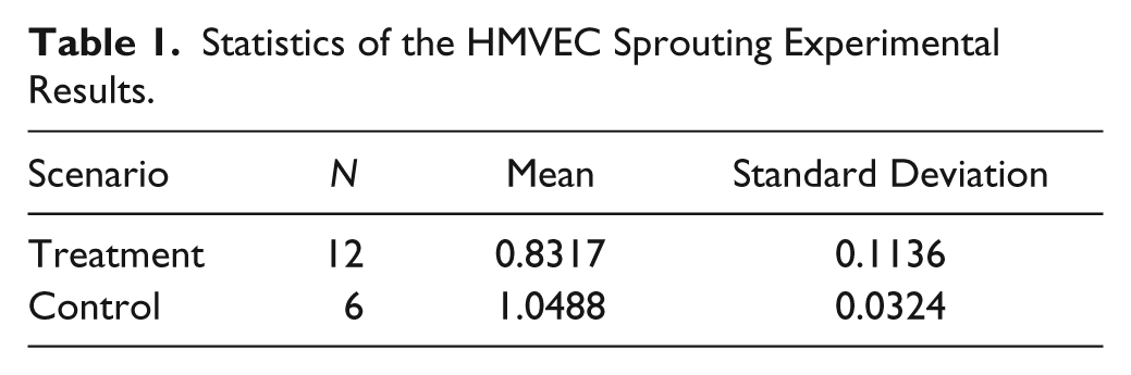
For the case of the treatment, the localized mechanical stimulus was observed to have effectively hindered the growth of the sprouts and caused them to retract 16.83% in height, without any apoptosis signals. For the case of the control, the sprouts in the slots adjacent to the targeted sprout were still in response to the VEGF gradient and the sprouts were observed to have grown by 4.88% in height. A paired t test was conducted to determine whether there was a statistically significant mean difference between the fractional elongation of the control and treatment groups, and the two-tailed p value was found to be 0.0019. Based on the conventional criteria, this p value is considered to be very statistically significant, therefore providing strong statistical evidence that the induced mechanical stimulus is likely to hinder the growth of the sprouts.
Summary and Discussion
We have presented an electromagnetic system (i.e., EMN) that is capable of generating a localized and spatially reconfigurable magnetic field and force. The EMN was implemented to induce a localized force gradient in an sECM, and the effects of the localized mechanical stimulus (in the form of a force gradient) on in vitro angiogenic sprouting of HMVECs were investigated.
We first devised an analytical model (using a system of magnetic dipoles) to determine the magnetic fields and forces in the vicinity of the designed EMN. Subsequently, the model is verified experimentally using a gauss meter equipped with a hall sensor probe. However, we found that there were discrepancies between the computed and measured fields. There are two main factors for the discrepancies; the first factor reflects the difference between the modeled and physical magnetic core. Our model considers the core as a stack of circular disk dipoles, whereas the physical core is a volume of point dipoles. The second factor involves the magnetization of the dipoles. Our model assumes each circular disk dipole is magnetized homogeneously, whereas the physical core of point dipoles may magnetize inhomogeneously due to imperfections (such as impurities) in the material. Nevertheless, to achieve a quantitative agreement between both data, a multiplicative scaling function is introduced.
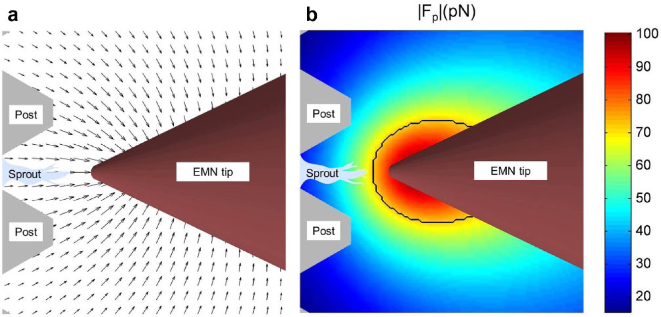
With the characterized EMN, we induced a localized force gradient in an sECM, and studied the effects of such a stimulus on in vitro angiogenic sprouting of HMVECs. The experimentally observed results showed that the sprouting of the HMVECs was distinctly inhibited by the applied mechanical stimulus. Time-lapse analysis of the images acquired from the experiments indicated a decrease of 16.83% in sprout height, without any apoptosis signals. One plausible reason for such an observed effect is the potential decrease of collagen density at the anterior region of the targeted sprout tip, which could be caused by the presence of the “pulling” forces in the sECM. By using the methodology to quantitatively compute magnetic forces (as described in the “Magnetic Induction Modeling” section), the force vector field induced by the EMN in the sECM is calculated and depicted in Figure 9a . The force vector field showed that the forces acting on the particles in the sECM (that are bioconjugated with the collagen fibers) could have pulled and deformed the fibers toward the EMN tip, causing a sparsity of fibers at the anterior region of the sprouting tip, and possibly creating difficulties for the sprouting tip cells to protrude and migrate. This can be explained with the motor-clutch model developed in Chan and Odde 38 and Mitchison and Kirschner. 39 The model suggests that a reduced collagen fiber density ECM (which can be considered to be corresponding to a reduced rigidity of the ECM40,41) would weaken the resistance experienced by the sprouting tip cells in the myosin-driven retrograde flow, thus undermining the protrusion of the tip cells. Other studies have also shown that endothelial cells migrate preferentially on rigid substrates.42 –44
(
With the designed EMN, the induced mechanical stimulus is localized, and this is evident from the experimental results, where it can be seen that the sprout in the slot adjacent to the targeted sprout is unaffected and was still in response to the VEGF gradient, with an increase of 4.88% in height. This observation is consistent with the available experimental results reported in Chen et al. 23 and Herath et al., 24 in which sprouts in an sECM without the application of the magnetic field would migrate in the direction of the VEGF gradient. Therefore, this shows that the forces applied at the area of the targeted sprout are localized and do not affect the growth of other sprouts nearby. With our model for computing magnetic forces (as described in the “Magnetic Induction Modeling” section), we identified a localized area within which the induced forces have the largest effect on the embedded particles in the sECM. The degree of localization is assessed by identifying the region where the magnitude of the applied force is greater than 1/√2 or 70.7% (i.e., half power region). 45 Figure 9b depicts the localized area on the sECM, where the region is traced by a black boundary. The result shows that the force gradient induced by the EMN is concentrated at the anterior region of the targeted sprout.
The magnetic technique applied to sECM appears to mimic durotaxis, which is a form of cell migration guided by matrix stiffness gradients. Several works20 –22 have already shown that by embedding magnetic particles in ECM and by applying an external magnetic field, the stiffness of the ECM can be mechanically manipulated. While these works provided useful insight on the mechanical properties of the ECM, how mechanical stimulus (in the form of a force gradient) directly affects the cell behaviors still remains preliminary and several issues need to be clarified. First, the effect of a number of parameters (such as the strength of the magnetic force gradient and the particle concentration in the ECM) on the stiffness of the sECM remains to be explored. Second, the question of how the direction of the applied force gradient with respect to the heading of a sprout (such as in the case when they are perpendicular to each other) may affect angiogenic sprouting remains open. It is an important issue to consider for future research, particularly in the context of using a localized force gradient generated by the proposed magnetic micromanipulation technique. Third, the reversibility of the effects induced by the localized stimulus in the sECM needs to be investigated. The reversible effects may allow real-time manipulation of the ECM, which could provide insight as to how cells process cues from their surrounding environment and could also offer new opportunities to tailor a cell’s local microenvironment in a biologically relevant fashion. This is particularly important to tissue engineering where the mechanical properties of the ECM affect the local behaviors of cells and contribute to the success of the tissue engineering implants. Such issues notwithstanding, the results reported in this article to point to the prospect of selectively controlling the in vitro behavior of cells by the induction of a localized force gradient in the ECM.
Utility of the Proposed Magnetic Induction Model
We devised an analytical model for determining the magnetic induction of the designed EMN that is accurate at any location outside of the conductor. Specifically, it is capable of estimating magnetic fields produced by the EMN and the forces applied on the magnetic particles that were induced by the field.
The proposed model is not bounded to the utility of this article; it can be used to facilitate the synthesis of closed-loop controllers for automated operation of magnetic manipulation systems. This is especially useful in applications where active manipulation of magnetic particles is required and can be realized through varying the strength of the applied forces dynamically. Hence, in such a case, the model can be readily utilized and provides an efficient way to determine the required parameters to produce the desired forces for the intended purpose.
Footnotes
Appendix A
Appendix B
Acknowledgements
The authors would like to thank Ms. Vikeka Kalidasan for her help in acquiring the magnetization curve of the soft magnetic core. We are particularly grateful to the BioSystem and Micromechanics Interdisciplinary Research Group (BioSyM), under the Singapore-MIT Alliance for Research and Technology Program (SMART), for the use of facilities to conduct the experiments.
Declaration of Conflicting Interests
The authors declared no potential conflicts of interest with respect to the research, authorship, and/or publication of this article.
Funding
The authors disclosed receipt of the following financial support for the research, authorship, and/or publication of this article: This work was funded by the A*Star Science and Engineering Research Council, Singapore, under the Public Sector Funding Grant (Project No. 1321202077). S.C.B.H. would like to acknowledge the financial support provided by the National University of Singapore and SMART. Y.D. would like to acknowledge the financial support provided by the China Scholarship Council.