
Abstract
Electrospun porous beaded fibers show great potential in the industrial application of many different fields; in addition, the processing parameters play an extremely important role in producing the required porous beaded fibers. In this study, polystyrene porous beaded fibers were fabricated via the electrospinning method. To further research into the formation mechanism of the electrospun porous beaded fiber, the influences of both flow rate and applied voltage on the jet motion and surface morphology of polystyrene porous beaded fibers were investigated in a systematic and comprehensive way. Images of jet trajectories and fiber morphologies under selected parameters were captured by high-speed photography and scanning electron microscopy, respectively, to explore the formation mechanism of porous beaded fibers. The experimental results showed that both flow rate and applied voltage have tremendous influence on the jet pattern and resultant fiber morphology, namely, the higher flow rate results in a multi-jet pattern and larger bead diameter, and the larger applied voltage leads to multi-jet trajectory and a reduction in the number and diameter of beads.
Introduction
Electrospinning has become a widely available technology that is used for producing microfibers and nanofibers. Recently, a breakthrough in its development and fiber engineering has been made; consequently, the electrospinning technology has been successfully applied to a wide range of fields, such as biomedical vascular tissue scaffold construction, wound healing, cell culture,1 –3 food preservation, inhibition of bacterial regeneration,4,5 food processing,6,7 and auxiliary energy collection. 8 Providing excellent properties, the nanostructure of electrospun fiber is capable of meeting the needs of various fields. However, an unstable jet, which is caused by different reasons and leads to the beading phenomenon, can be observed frequently in the process of electrospinning. With the research and development of nanofibers, the unique advantages of beaded fibers in many aspects have been developed successfully.
Owing to its large specific surface area and small diameter, the beaded fiber is an ideal choice for medicine. 9 The beaded structure of nanofibers exhibits its potential in the formation of a new and effective drug delivery system that is used for delivering bioactive agents to guide cell proliferation and even differentiation. 10 Besides, the beaded structure can also be used in the field of composites. The intermittent bead placement not only enhances fiber anchoring on the substrate but also dissipates the energy by means of deforming the substrate during failure. Compared with composites without microspheres, the stiffness of the composites with microspheres has been improved, especially when the microspheres are larger and stiffer than the surrounding matrix. 11 These above-mentioned excellent properties of beaded fibers have a close relation to the electrospinning process. During the electrospinning process, the liquid is extruded from the spinneret to produce a pendant droplet as a result of surface tension. Soon afterward, the droplet is deformed into a Taylor cone under the action of electrostatic repulsion (upon electrification) among the surface charges that are featured by the same sign since when a charged jet is ejected. Subsequently, the jet extends in the form of a straight line. Ultimately, it undergoes vigorous whipping motions because of the bending instability.12 –16 During this period, due to the radial repulsion of the same surface charge and the influence of surface tension along the jet velocity, axisymmetric instability may be generated, which will lead to the formation of beaded structure. 17 The scope of application of beaded fibers in various fields is determined by the number and diameter of the bead. Moderate bead size and quantity contribute to the low pressure drop. Based on this direction, Wang et al. 18 prepared an air filter with porous beaded nanofiber mesh, benefiting from the electrospinning technology (by means of adjusting the solvent system and polymer concentration) and taking the polylactic acid as raw material. Not only the small fiber diameter but also the nanopores on the beads contribute to the high filtration efficiency. In the research of composite materials, beaded fibers are often embedded in resin matrix as reinforcement. Compared with smooth fibers, beaded fibers require greater force to pull out of the resin matrix. The reason is that the beads have a larger surface area, which causes them to come into contact with the matrix more fully. If the beads have smaller diameter, this may improve the strength of the composite material. In this regard, Rodricks et al. 19 noted that smaller beads yield higher increases in pullout force and work, which leads to the possibility of multiple beaded fiber application in practical composites. It is worth mentioning that flow rate and voltage are two important factors that affect the number and diameter of bead. 20
In recent years, the porous fibers have attracted extensive attention because of their high specific surface area and porosity. In the process of electrospinning, a double-diffusion process with the surrounding media along the direction of jet motion is formed by the materials included in the jet (mainly, polymer molecular chains and solvent molecules). In addition, solvent volatilization occurs on the surface of the polymer jet. This process, usually, is accelerated by the rapid unstable motion and is beneficial to the formation of porous structure on fiber surface.21 –23 Fuat Topuz et al. 24 prepared hydrophobic nanofibrous electrospun mats from intrinsically microporous polyimide with pendant trifluoromethyl groups. By observing the absorption effect to oil and non-polar compounds in the fiber matrix on the fiber mat, it can be concluded that the high adsorption capacity of the material is attributed to the hierarchically porous nature of the fiber mat rather than its adsorption effect on the surface. The mats exhibit potential in the application of the removal of oil and chemical leakages. It has commonly been known that the infiltrating-type bead is characterized by exceedingly high surface energy and prone to absorb the materials from the air. Under the condition of pore structure added on the bead surface, the satisfactory effect of the fiber to absorb the impurities will be achieved. In view of this, it can be used in the fields of air filtration, 25 carbon dioxide adsorption, 26 and self-cleaning. 27
At present, research works in the field of porous beaded fibers have only focused on the application of pore structure and beaded structure. However, few scholars have been able to draw on any systematical analysis on the formation mechanism and morphological changes of porous beaded fibers under different factors. In this article, by means of high-speed photography and scanning electron microscopy (SEM) and from the perspective of the formation mechanism of porous beaded fibers, the images of jet behaviors and surface morphologies of the electrospun porous beaded fibers under different flow rates and applied voltages were captured and characterized so as to explore the formation mechanism of porous beaded fibers.
Experimental
Materials
Polystyrene (PS, (C8H8)n, average Mw = 350,000, ρ = 1.05 g/cm3; Sigma-Aldrich Co., Ltd., USA) and N,N-dimethylformamide (DMF, analytical grade, C3H7NO, molecular weight = 87.12; Sinopharm Chemical Reagent Co., Ltd., China) were used as received without any further processing. Seven grams of PS powder was dissolved in 93 g of DMF solution at room temperature by an electric mixer (JB90-D; Shanghai Specimen and Model Factory, China); thus, 7 wt% polystyrene solution was prepared.
Experimental Setup
Figure 1 shows the schematic diagram of the homemade electrospinning machine (TH-001; Lai Zhou Electronic Equipment Co., Ltd.) used in this study, mainly consisting of a high-voltage power supply system, a polymer solution feeding system, a temperature and humidity control system, and a high-speed camera system. The high-voltage power supply system is used to apply the voltage to the spinneret and the collector to obtain the polarized polymer. The polymer feeding and spinneret system was placed on a track, which could move horizontally during the spinning process at a constant speed of 35 cm/min. Driven by a syringe pump, the polymer solution was fed from the syringe into the needle via a silicon tube. The outer diameter of 0.7 mm, the inner diameter of 0.4 mm, and the length of 13 mm of the flat-headed stainless steel needle were used in this experiment. In addition, the working distance between the spinneret and the collector was 15 cm. A metal rotating drum coated with aluminum foil was adopted as the collector in this study. The feeding rate, rotating speed of the collector, and spinning time were set to 2 mm/min, 12 rpm, and 2 h, respectively, intended for collecting continuous fibers. Controlled by a temperature and humidity control system, an ambient temperature of 25°C ± 3°C and a humidity of 40% ± 5% were adopted in this experiment. Two groups of porous beaded fiber were fabricated in this study, and the processing parameters are shown in Table 1.
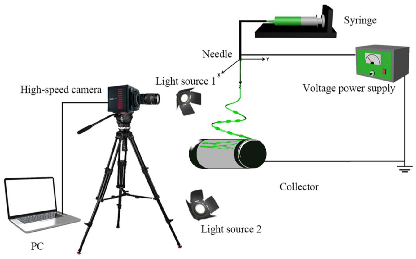
Schematic diagram of experimental setup.
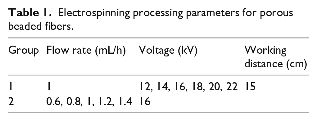
Electrospinning processing parameters for porous beaded fibers.
The images of jet motion during the electrospinning process were captured by the high-speed camera system, that is, the Photron Fastcam Mini AX200 High-Speed Camera (Photron Ltd, Tokyo, Japan). It is equipped with a Tokina 100 mm f 2.8 macro lens, which can record the images at a frame rate of up to 900,000 frames per second (fps) with a maximum shooting resolution of 1504 × 1128 pixels. Two 100 W spotlights (Model-100LED TWIN; Shanghai Jinqiao Jingyi High-Tech Co., Ltd., Shanghai, China) were used for light compensation to enhance the picture shooting quality.
Characterization
The surface morphology of the PS nanofiber was observed by an optical electron microscope (BH200M; Ningbo Shunyu Instrument Co., Ltd.) and an SEM (Field Emission Scanning Electron Microscope, SU8010; Hitachi, Japan). The fiber diameter was calculated by the image visualization software (ImageJ; NIH Image, Bethesda, MD, USA). Adobe Photoshop (CC 2019; Adobe Systems Software Ireland Ltd, Ireland) software was used for post-processing of images captured by the high-speed camera.
Results and Discussion
Effects of Flow Rate
Figure 2 shows the jet motions of the PS fibers at various flow rates (0.6 mL/h, 0.8 mL/h, 1 mL/h, 1.2 mL/h, 1.4 mL/h), under the circumstance of the applied voltage of 16 kV. The white circle in the following figure represents a segment of the jet whipping, and also, the white square on the upper-left corner is the magnified view of this segment. It can be observed that there are a number of white flash points within the whipping areas of the jet motions at five different flow rates. These flash points, in fact, are specular reflections of liquid beads under the irradiation of the high-speed photography supplement, which indicates that there is a string of beaded structure in the whipping area of the jet motion.
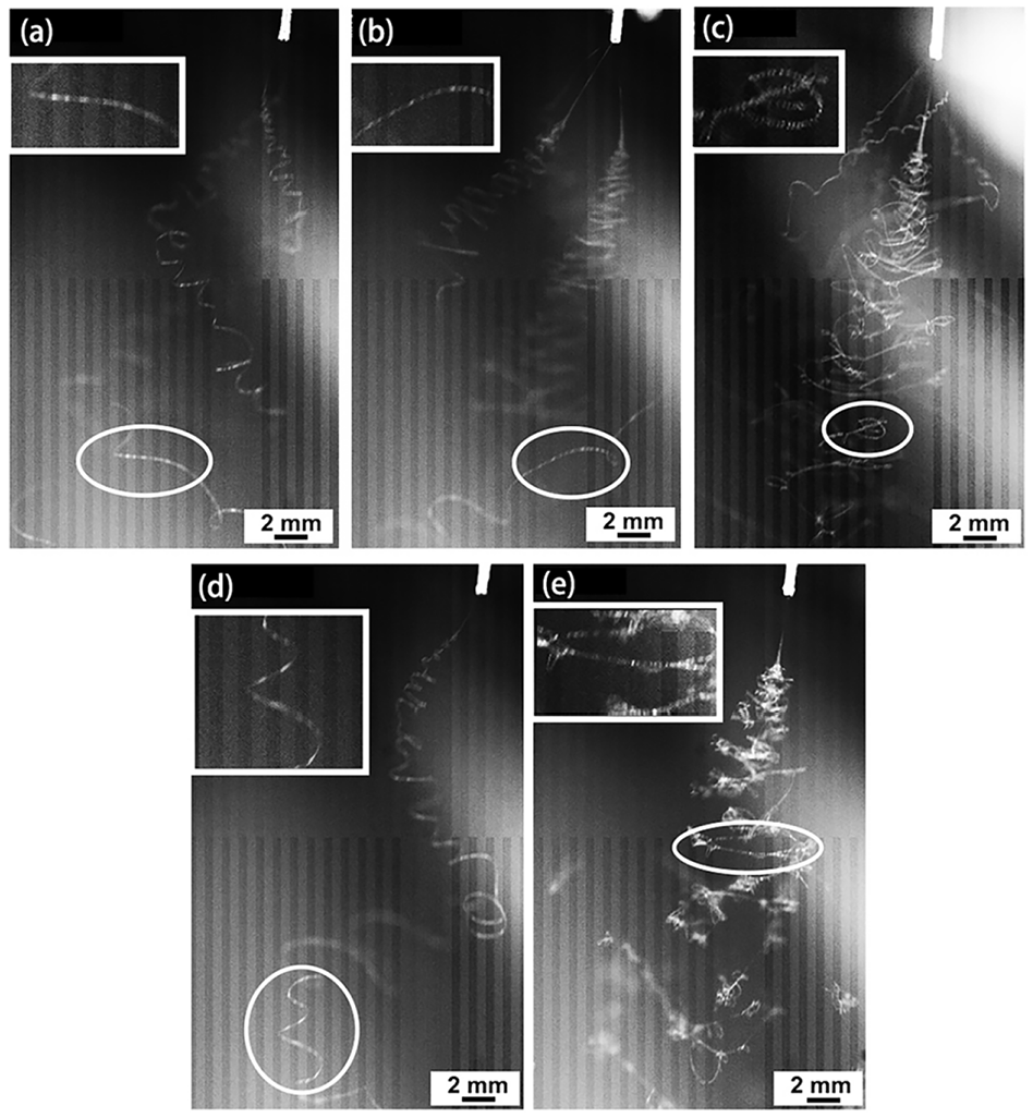
High-speed images of jet motions of electrospun PS porous beaded fibers at different flow rates: (a) 0.6 mL/h, (b) 0.8 mL/h, (c) 1 mL/h, (d) 1.2 mL/h, and (e) 1.4 mL/h.
As can be seen from Figure 2, multiple jets emerged from the spinneret when the flow rate is within the range of 0.6–1 mL/h, while multiple jets change into a single one when the flow rate is greater than 1 mL/h. The main reason for this phenomenon is that the increased flow rate leads to an increase in the volume of fluid ejected from the spinneret, and besides, the induced charge generated by the electric field on the liquid surface increases. Since the intensity of the electric field has effects on the distribution of induced charge and there is a repulsive force between induced charges, as a consequence, the phenomenon of multi-point aggregation of induced charge is formed on the surface of the fluid, which leads to the generation of the main jet and the fractional jet. When the flow rate reaches a certain value, the electric field force generated by the induced charges is far greater than the repulsive force between the charges, and the fluid is gradually stretched into a main jet. In the case of a flow rate of 1.4 mL/h, the jet trajectory becomes unclear and the magnified view in the upper-left corner shows that the jet begins to be split into smaller jets in the whipping region. The high flow rate leads to the high density of excess charge on the surface of the jet, followed by undulations formed on the surface of the cylindrical jet. These undulations gradually become large enough and then unstable, and initiated branches expand outward from the primary jet. Under the action of electric field, integrations both inside and between the branches occur, resulting in the blurring jet whipping trajectory.
Figure 3(a)–(e) shows the morphologies of PS porous beaded fibers that were collected at different flow rates and obtained by means of the optical electron microscope and scanning electron microscope. The small block diagrams in the upper-right corners show the enlarged beaded structures of the electrospun fibers. Spindle-like structured beads with a lot of micropores of different sizes on the fibers can be observed. Due to the solvent evaporation in the process of electrospinning, the micropores are formed on the surface. Figure 3(f) shows the diameter distributions of beads at various flow rates, and the diameters of spindle-shaped beads can be measured by the maximum width of the bead along the direction perpendicular to the axial direction of the fiber. Each point in this figure indicates one individual measurement of a single fiber section obtained from a single sample. The length of the left line represents the distribution range of the bead diameter, and besides, the length of the middle line represents the average diameter. What can be clearly seen from this figure is that the bead diameter increases with the increase in flow rate, in a gradual manner.
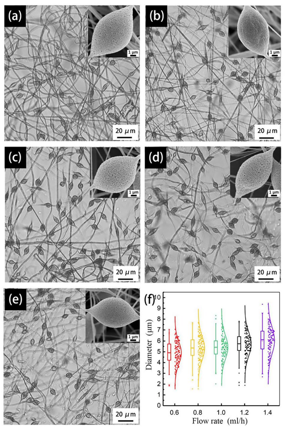
Micrographs and diameters of electrospun PS porous beaded fibers at different flow rates: (a) 0.6 mL/h, (b) 0.8 mL/h, (c) 1 mL/h, (d) 1.2 mL/h, (e) 1.4 mL/h, and (f) diameter distribution of beads in porous beaded fibers.
Effects of Applied Voltage
Figure 4 shows the jet motions of PS fibers with different applied voltages (14 kV, 16 kV, 18 kV, 20 kV, 22 kV), at a flow rate of 1 mL/h. It can be observed from the images of jet whipping and the enlarged views of this area that there are white flash points in the jet under all five different voltages, which indicate that a series of beaded structures appear on the electrospun fibers. As revealed by Figure 4(a)–(d), multiple jets are ejected from the spinneret. The greater the applied voltage, the more the jets. This is mainly due to the increase in excess charge density on the fluid surface which is caused by the increase in applied voltage; the fluid surface becomes unstable and then results in multiple jets. In Figure 4(e) with a voltage of 22 kV, it can be observed that there is a slight decrease in the number of jets. A possible explanation for this result may be that the high applied voltage leads to the generation of a great many small jets. Characterized by small diameters, the images of these jets were captured. However, it is extremely difficult for high-speed photography to capture distinct enough images. Consequently, the number of jets which can be observed in the figure decreases. By comparing among the whipping trajectories of jets under five different voltages, a conclusion can be drawn that the whipping trajectory of the jet gradually becomes unclear with the increase in applied voltage. It is probable that the jet will be refined in the whipping motion in a gradual way. In addition, the repulsive force between the jets becomes greater, which makes the refined jet unstable and more dispersed. In view of the above-mentioned factors, it is impossible for the high-speed photography to capture the distinct image of whipping trajectory.
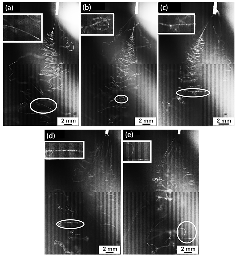
High-speed images of electrospun PS porous beaded fiber jets under different voltages: (a) 14 kV, (b) 16 kV, (c) 18 kV, (d) 20 kV, and (e) 22 kV.
Figure 5(a)–(e) shows the morphologies of PS beaded fibers collected under different applied voltages. It can be observed from the small block diagrams in the upper-right corners that the beaded structures are spindle-like under various voltages and many micropores of different sizes are displayed on the fibers. What is striking in this image is that the number of beads on beaded fibers decreases with the increase in applied voltage. Moreover, it can be clearly seen from Figure 5(f) that the average diameter of beads decreases with the increase in voltage. It seems possible that the high voltage leads to the stronger effect of the electric field force on the solution, while the flow rate (volume) of the jet remains unchanged. Therefore, the more the polarized charges in the jet solution, the greater the drafting force of the jet solution. Under this condition, it is rather difficult for the beads to be formed. As a result, the number and plumpness of beads decrease and the fibers with uniform diameter increase.
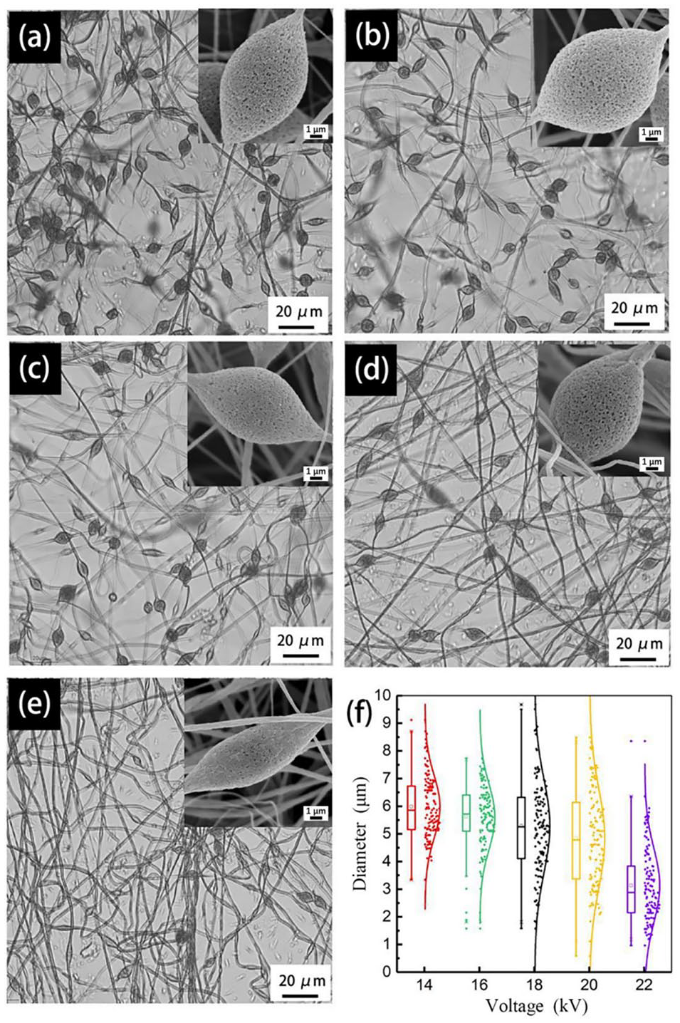
Micrographs and diameters of electrospun PS porous beaded fibers under different voltages: (a) 14 kV, (b) 16 kV, (c) 18 kV, (d) 20 kV, (e) 22 kV, and (f) diameter distributions of beads in porous beaded fibers.
Formation Mechanism of Multiple Jets
The multiple-jet mode is, usually, developed from the cone-jet mode. It can be realized by increasing the applied voltage and reducing the flow rate. Generally speaking, the Taylor cone starts to incline at the time when the jet is initially formed. That is to say, a jet is emitted from the edge of the liquid level of the nozzle. However, two or even several jets are sprayed quickly and then take shape at the liquid level of the nozzle because of the unstable jet at that moment. 28
In the electrospinning process, the polymer solution is ejected from the spinneret and rapidly moves toward the rotated collector under the action of an electric field. At first, since the surface tension and viscoelastic force of the jet are smaller than the force exerted by the applied electric field, the jet in the initial stage of acceleration is continuously stretched to be thinner under the action of the electric field force. At this point, the jet keeps moving in a straight line and a stable short-distance movement occurs, which can be considered as the linear whipping motion of the jet. 29 However, because the charges on the jet surface are subjected to mutually exclusive forces, the surface charge distribution appears uneven under the action of a non-axial electric field, as shown in Figure 6. It is worth noting from the figure that a lateral projection occurs to the jet. Finally, it leads to the unstable jet, and besides, it makes the jet be split or do the non-linear spiral motion. 30
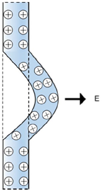
Schematic diagram of jet instability.
Figure 7 shows three unstable stages of jet motion of continuous electric bending instability proposed by DH Reneker and Yarin, 31 and the first and second unstable bending regions of the jet motion can be observed by the high-speed camera in this study. In the electrospinning process, the behavior of conical jet is influenced by such factors as the properties of solution, flow rate, applied voltage, and other factors, individually or collectively. Figure 8 displays the five jet patterns observed in this study. Figure 8(a) shows the single-jet precession mode. The jet moves along an axis (along the direction of the needle tip) in a top-down axial whipping motion, which can be observed in Figure 2(d). Figure 8(b) shows the multiple-jet precession mode. Multiple jets, ejected from the needle tip, are under their own whipping motion. In this mode, the jets move spirally from top to bottom, the direction of the needle tip can be deemed as the axis, and the whipping is driven by the jets themselves, as revealed by Figure 2(a). Figure 8(c) shows the single-jet bifurcation mode, which mainly embodies the increase in charge on the concave surface of the jet, and the jet splitting mode is changed from the axial instability splitting mode to the bending and whipping instability splitting mode. In addition, the jet diameter can be rapidly reduced because of jet whipping, corresponding to Figure 2(e). Figure 8(d) shows the multiple-jet mode. Generated by the high electric field intensity, multiple jets are formed at the needle tip at the same time. In this mode, the main jet moves along the direction of the needle tip and the separate jet rotates, as shown in Figure 4(a). Figure 8(e) shows the multiple-jet precession and bifurcation mode, that is, multiple jets are jetted out from the needle tip, the main jet in the middle appears in the form of bifurcation mode, and the sub-jet beside is displayed in the form of precession mode. Figure 2(c) and Figure 4(b) and (c) demonstrate the multiple-jet precession and bifurcation mode.

Three stages of electrospun jet with continuous bending instability.
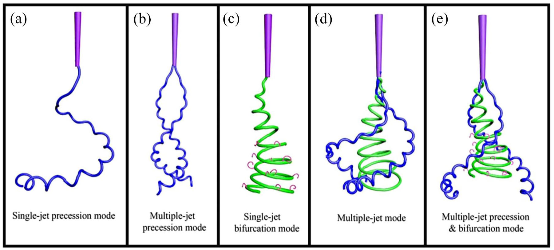
Jet patterns: (a) the single-jet precession mode, (b) the multiple-jet precession mode, (c) the single-jet bifurcation mode, (d) the multiple-jet mode, and (e) the multiple-jet precession and bifurcation mode.
Formation Mechanism of Porous Beads
It has universally been acknowledged that the entanglement degree of molecular chain in the polymer solution is lower with smaller solution concentration. On the other hand, the polymer solution exhibits a large electrical conductivity, which makes the jet carry more charges in the spinning process. As a result, the axial electric field force and the repulsion force between surface charges become strong, as shown in Figure 9(a). Since the molecular chains fail to be entangled to the extent of effectively resisting the stretching by external forces, they break finally. 32 In the meantime, due to the effect of viscoelasticity of the polymer chain and the surface tension of the solution, the broken jets or droplets formed on the surface of the Taylor cone tend to contract with each other. As a result, it is too late for the molecular chain to be stretched and oriented, and it is eventually solidified into polymer microspheres. However, part of the molecular chains is stretched orientationally and then solidified into extremely fine fibers, as shown in Figure 9(b). This process leads to the formation of a string of beaded fibers.33,34 With the increase in solution concentration, the entanglement degree of molecular chain increases, and the external electric field force of the jet will be relatively uniform in the process of transformation from one-dimensional linear motion to three-dimensional spiral motion. Therefore, the number of spherules in the fiber membrane will decrease, and the number of fibers with uniform diameters will increase accordingly.
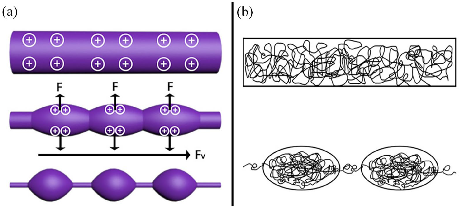
(a) Schematic diagram of the forces exerted on fibers during bead formation; (b) schematic diagram of molecular entanglement in the fiber during bead formation.
Figure 10 shows the schematic diagram of the formation mechanism of porous beaded fibers. The jet moves at a high speed from top to bottom; in addition, the solvent (DMF) volatilization and solute solidification occur in the process of jet motion during electrospinning. Due to the DMF volatilization and the diffusion of non-solvent substances (including non-solvents, such as air and water vapor), the thermodynamic instability of the jet leads to the phase separation of the jet. In this process, there are solvent volatilization and vapor diffusion, which induce phase separation phenomena. 35 Thermally induced phase separation caused by rapid solvent volatilization leads to polymer enrichment and DMF enrichment in the jet, the volatilization after DMF enrichment solidifies the polymer enrichment phase, and finally the open porous structure is formed on the fiber surface. 36
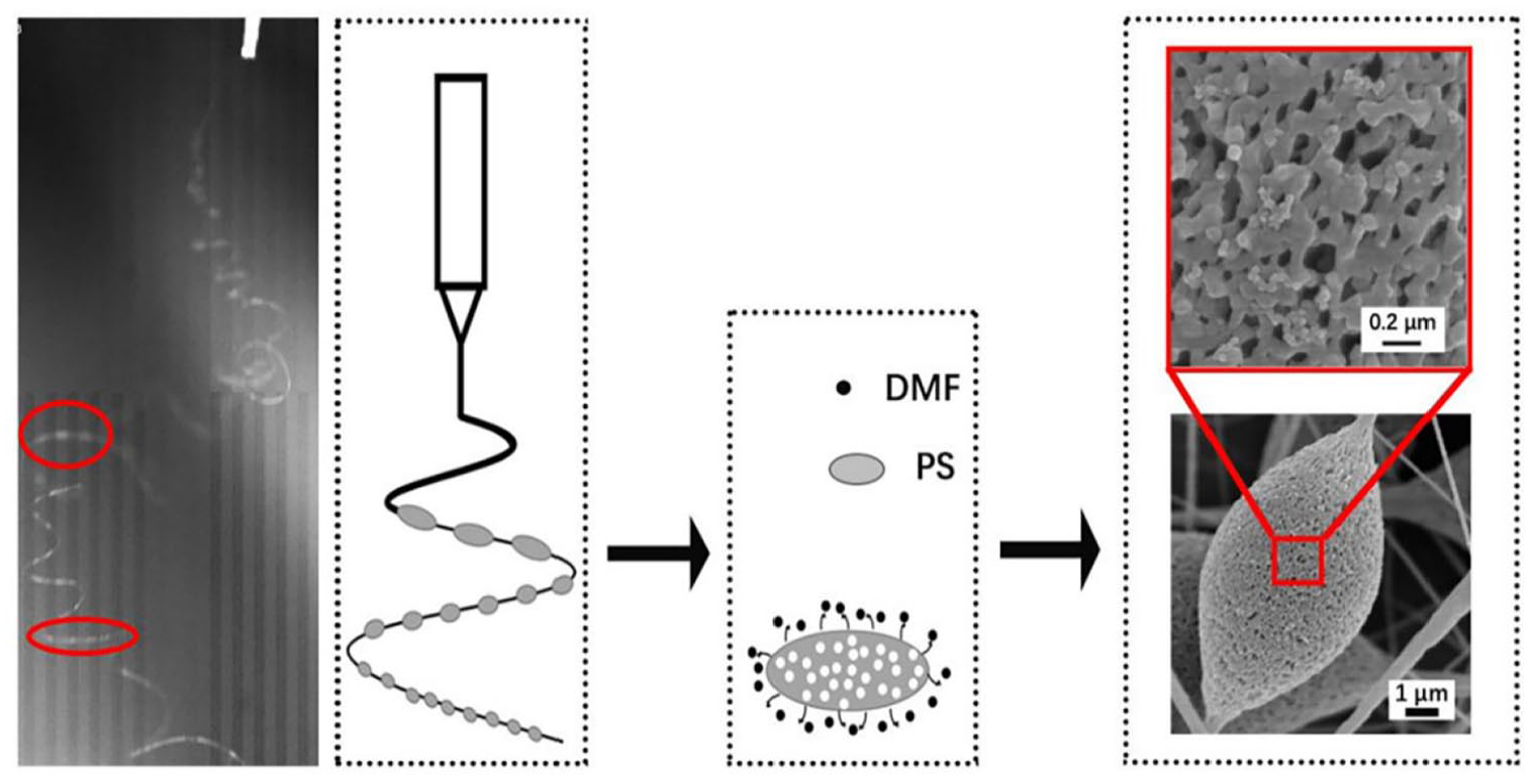
Schematic diagram of the formation mechanism of porous beaded fibers.
Conclusion
The electrospun PS porous beaded fibers were fabricated and their formation mechanism was investigated in this study. The images of jet behaviors under different flow rates and applied voltages were captured using high-speed photography, and the surface morphologies of fibers were observed by the SEM equipment. It can be seen from the experimental results that a higher flow rate results in a higher density of excess charge on the jet surface; the resultant surface instability undulations generate branching jets, which shows the multi-jet pattern in the electrospinning process. At the same time, the bead diameter on the fiber will increase as the jet volume increases. High voltage will cause jet surface instability, resulting in multiple-jet phenomena. There is no doubt that the applied voltage will directly affect the entanglement degree of the molecular chain inside the jet. The continuous increase in the axial electric field intensity has an enormous effect on the axial over-stretching of molecular chain, which will be directly reflected in the significant decrease in the number and diameter of bead. In addition, solvent volatilization and solute solidification have significant influences on the microporous structures all over the fiber surface.
Footnotes
Declaration of conflicting interests
The author(s) declared no potential conflicts of interest with respect to the research, authorship, and/or publication of this article.
Funding
The author(s) received no financial support for the research, authorship, and/or publication of this article.