
Abstract
The present study is an attempt to fabricate composite nanofiber mats from polystyrene (PS) loaded with exfoliated graphite nanosheets (EGNS) by using electrospinning technique. EGNS with different weight ratios of 3, 6, and 9 wt.% were added to PS (20 wt.%). The fiber diameter and morphology of the composite nanofiber mats were investigated by scanning electron microscopy (SEM). Results revealed that as EGNS concentration was increased, the average diameter of EGNS/PS electrospun nanofibers decreased. Differential scanning calorimetry (DSC) and thermogravimetric analysis (TGA) were used to investigate the thermal properties. The tensile strengths and Young’s modulus of the composites improve with the increasing EGNS concentrations compared to PS nanofiber, which indicates 84% and 88% augmentation, respectively at 6 wt.% of EGNS. Also, the addition of EGNS increased thermal stability of composite nanofiber mats.
Introduction
Polystyrene is a commodity polymer with cumulative commercial applications.1–3 Polystyrene is a homopolymer made up of styrene monomers. It is a thermoplastic engineering material. Polystyrene has also been used to form the nanofiber nanostructures.4,5 Polystyrene has been commonly used in the automobile parts, electronics, household usages, plastic toys, etc. The high-impact polystyrene has been developed to reduce the problem of structural stiffness. 6 Polystyrene has unique chemical and physical properties to be employed as nanofibers.7,8 The expanded polystyrene has also been prepared for the nanofiber applications.9,10 Both the polystyrene and expanded polystyrene have been used to form the inexpensive, dimensionally stable and versatile nanofibers. The polystyrene-based nanofibers have been used to form the nanocomposites for the membrane formation and other technical applications.11–13 Such nanofibers have also found potential for the water-oil separation, devices, and biomedical relevance.14–16
Graphene oxide, also known as graphite oxide, graphitic oxide, or graphitic acid, is usually prepared by the treatment of graphite flakes with oxidizing agents so that polar groups are introduced on the graphite surface, thereby widening the interlayer spacing of the graphene planes. 17 GO, first prepared by Brodie in 1859, typically involves the reaction of graphite flakes with potassium chlorate and fuming nitric acid. 18 Hummers and Offeman developed GO, which is prepared by reacting anhydrous sulfuric acid, sodium nitrate, and potassium permanganate, which is widely followed even today. 19 Graphite was added to a solution of concentrated sulfuric and concentrated nitric acid, which was constantly stirred for 20 hours at room temperature to generate the graphite intercalation compounds (GICs). Graphite intercalation compounds (GICs) are formed by the insertion of atomic or molecular layers of different chemical species between the layers of the graphite host lattice.20,21
In GICs, the graphene layers either accept electrons from or donate electrons to the intercalated species. Graphite intercalated by electron donors like alkali metals (e.g., potassium, sodium, etc.) is known as donor-type GICs, whereas compounds formed by the intercalation of molecular species acting as electron acceptors like halogens, halide ions, and acids are known as acceptor-type GICs. The acids involved in forming GICs include nitric acid, sulfuric acid, perchloric acid, and selenic acid. Incidentally, graphite bisulfate is the most commonly used GIC to prepare GNPs for the fabrication of polymer/graphite nanocomposites. 22 Biodegradable thermoplastic matrices were improved in terms of their thermal, mechanical, and electrical conductivity by using graphene nanoplatelets (GNPs) as multifunctional nanofiller. 23 Nanomaterials based on graphene nanoplatelets offer unique uses in batteries, transistors, solar cells, and electromagnetic interference shielding.24-25
The polymeric fibers including polystyrene have been usually processed using electrospinning technique. The electrospinning technique is the most commonly used technique for making nanofibers from various polymers. 26 This technique also allows the modification over the fiber size, 27 fiber morphology, 28 and fiber composite with other materials to enhance the membrane functionalizatio. 29 The versatility of the electrospinning has been utilized to develop high quality air filters and masks, such as high-temperature air filter 30 and transparent air filter. 31 The electrospinning process is driven by the electrical forces on free charges on the surface or inside a polymeric liquid. When the electric field reaches a critical value at which the repulsive electric force overcomes the surface tension force, a charged jet of the solution is ejected from the tip of a cone protruding from a liquid drop of the polymer. As the jet stretches and elongates in the air, the solvent evaporates, leaving behind a charged polymer fiber that lays itself randomly on a collecting metal screen. Thus, continuous fibers are produced to form a non-woven fabric. 32
Electrospinning and impregnation procedures were used to create a polystyrene nanofiber membrane. Following, sawdust was added to the membrane for separation of oil spills. 33 Edge-styrene graphitic nanoplatelets (StGnPs) were produced without the aid of any extra chemical reactions by the in-situ mechanochemical reaction between graphite and styrene. 34 Electrospinning followed by calcination were used to produce ferric ceria nanofibers. 35 For efficient transdermal drug delivery, oxidized chitosan (OC) was chemically added to electrospun polyacrylonitrile nanofibers (PAN NFs). 36 Electrospun poly(4-chloro-3- methylphenyl methacrylate) and Ag-doped poly(CMPMA) composite nanofibers were utilized to remove bacteria like Escherichia coli and Bacillus subtilis from water. 37 Also The elimination of metal ions and microorganisms from water is shown to be a good candidate for the nanofibers. 38
This study examined the influence of various EGNS concentrations on the mechanical and thermal properties of PS electrospun nanofiber, concluding a comparison with EGNS/PS composite nanofiber mats in the same loading range. Using scanning electron microscopy (SEM), differential scanning calorimetry (DSC), thermogravimetric analysis (TGA), raman spectroscopy and tensile measurements, the composite nanofiber mats were evaluated.
Materials and methods
Materials
Graphite flakes (GF, particle size ≥75 mesh, 99.9% min purity, catalog number is 332461) was purchased from Sigma‐Aldrich, have been utilized as a raw material for producing EGNS. N,N-dimethyl formamide (DMF), nitric acid and sulfuric acid were supplied by Elnasr pharmaceutical chemicals Co., Egypt. A Commercial polystyrene (PS, scattered mm sizes beads shapes) loaded by EGNS for producing EGNS/PS nanofiber composites.
Exfoliation of graphite flakes
The preparation procedure of exfoliated graphite nanosheets (EGNS) as described in the literature.39,40 First, graphite flakes were added to a mixture of concentrated sulfuric and nitric acid (ratio 4:1 by volume). 41 The combination was stirred continuously for 24 hours at room temperature to create the Graphite Intercalation compound (GIC). Then, the GIC was washed with distilled water and dried at 100°C to remove any moisture. The dried particles were heat-treated and thermally shocked at 1050°C for 30 seconds to obtain expanded graphite. Finally, one gram of expanded graphite was immersed in a 600 ml alcohol solution (alcohol and distilled water with a ratio of 65:35). 42 After 16 of sonication, the dispersion was filtered and dried to get the EGNS before using it in the electrospinning process.
Preparation of EGNS/PS solutions
Exfoliated graphite nanosheets solutions were prepared with three concentrations of 3wt.%,6wt.%, and 9wt.% by dissolving in DMF solvent and were ultrasonicated for 16 h. Then, the PS (20 wt.% with respect to DMF) was added into the EGNS/DMF and were dissolved at a temperature of 60°C under continuous magnetic stirring for 12 h to obtain a homogeneous and well dispersed EGNS/PS/DMF polymer solution.
Electrospinning technique essentials
The polymer solution was placed into a 10 mL glass syringe that was connected to a stainless-steel needle (inner diameter of 0.9 mm). A high voltage power supply was employed to induce an electric field of 25 kV between stainless steel needle and a metal collector of 15x15 cm dimensions was grounded and centered horizontally. The electrospun fibers were collected on an aluminum foil covers the metal collector. The collector was located 20 cm vertical distance from the needle tip for the deposition of nanofibers and was adjusted for all experiments Electrospinning process employed in the present investigation.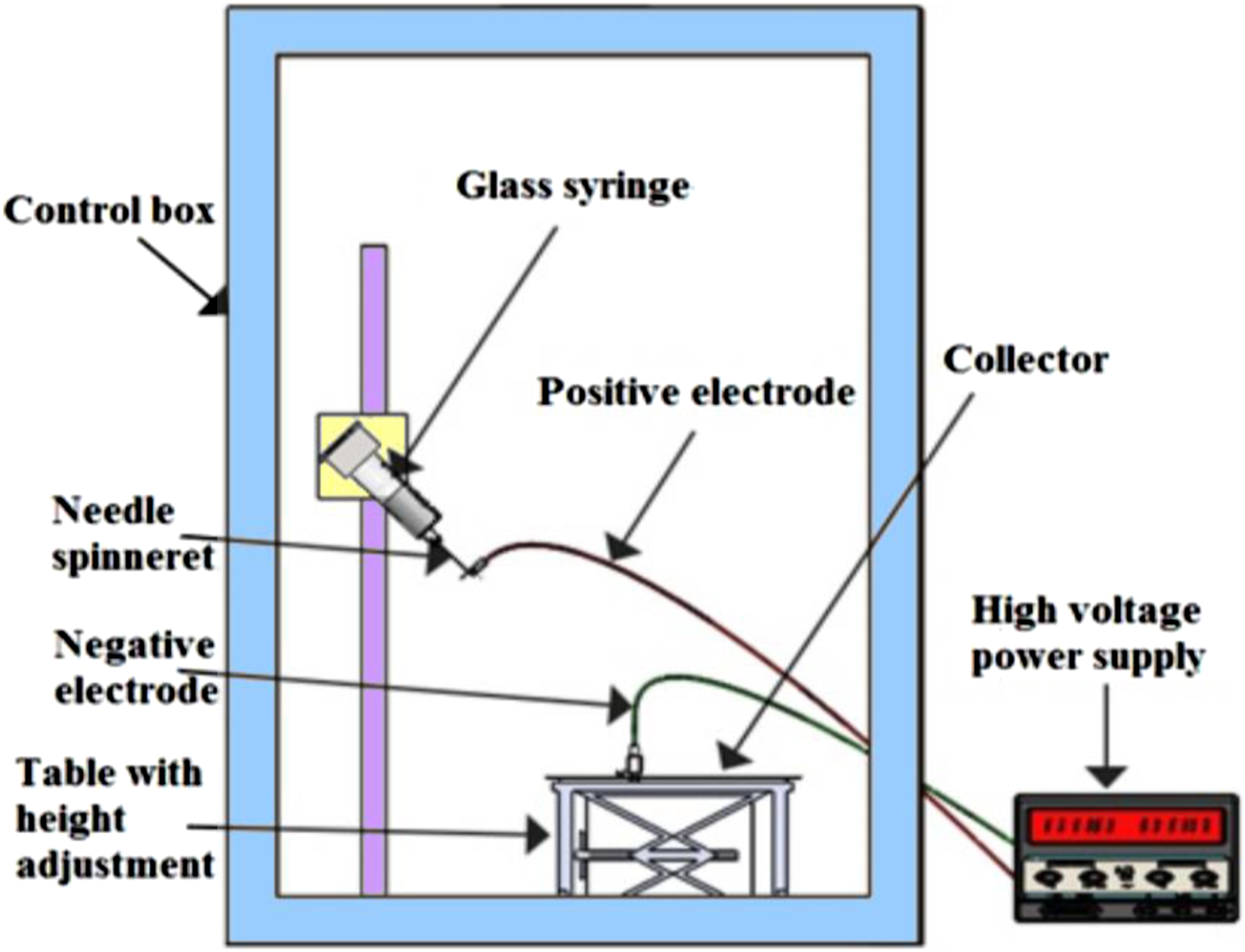
Intrinsic Viscosity Measurement
Intrinsic viscosity is defined as the ratio of solution specific viscosity (
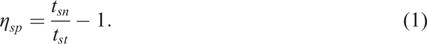
The intrinsic viscosity (

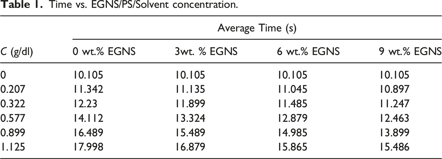
Measuring Time versus Polymer Concentration
Time vs. EGNS/PS/Solvent concentration.
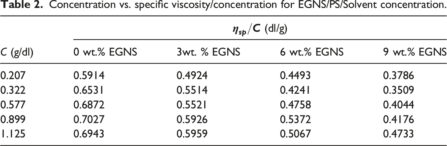
Concentration vs. specific viscosity/concentration for EGNS/PS/Solvent concentration.
Characterization of nanofiber mats
Nanofibers morphology analysis
The nanofiber mats morphology were characterized using scanning electron microscope (FEI Quanta 250, Hillsboro, Oregon-USA) at the Egypt Desalination Research Center of Excellence (EDRC), [Desert Research Center (DRC), Egypt].
Tensile test
A tensile test was conducted to estimate the stress-strain performance of exfoliated graphite nanosheets loaded in polymer composites. INSTRON testing machine (model 2519-107, National Research Centre (NRC), Egypt), with 5000 N maximum load cell capacity and strain rate of 0.2 mm/min, was conducted to study the tensile strength of PS and EGNS/PS nanofiber mats. Three Tensile samples of 40 mm gauge length and 10 mm width were trimmed from each combination, and the results were averaged. This showed the tensile strength of the polymer composites.
Differential scanning calorimetry
DSC technique (Scientific and Technology Center of Excellence, Cairo, Egypt - DSC Q2000), scanning from −80 to 350°C was conducted to get the thermogram and evaluate glass transition temperature (Tg).
Thermogravimetric analysis
Thermogravimetric analysis was performed by using a TGA instrument (TGA Q500 (Scientific and Technology Center of Excellence, STCE Egypt), scanning from 25 to 450°C at a heating rate of 10 ˚C/min to study the thermal stability.
Results and discussions
Intrinsic viscosity of EGNS/PS/Solvent concentration
The intrinsic viscosity values for EGNS/PS/Solvent concentrations have been computed from the intercepts of the fitting lines with the vertical axis is displayed in Figure 2. Table 3 indicates the calculated values of the intrinsic viscosity. Intrinsic viscosity (crossing with the vertical axis) for EGNS/PS/Solvent concentration polymer solutions. Intrinsic viscosity and Berry’s number values.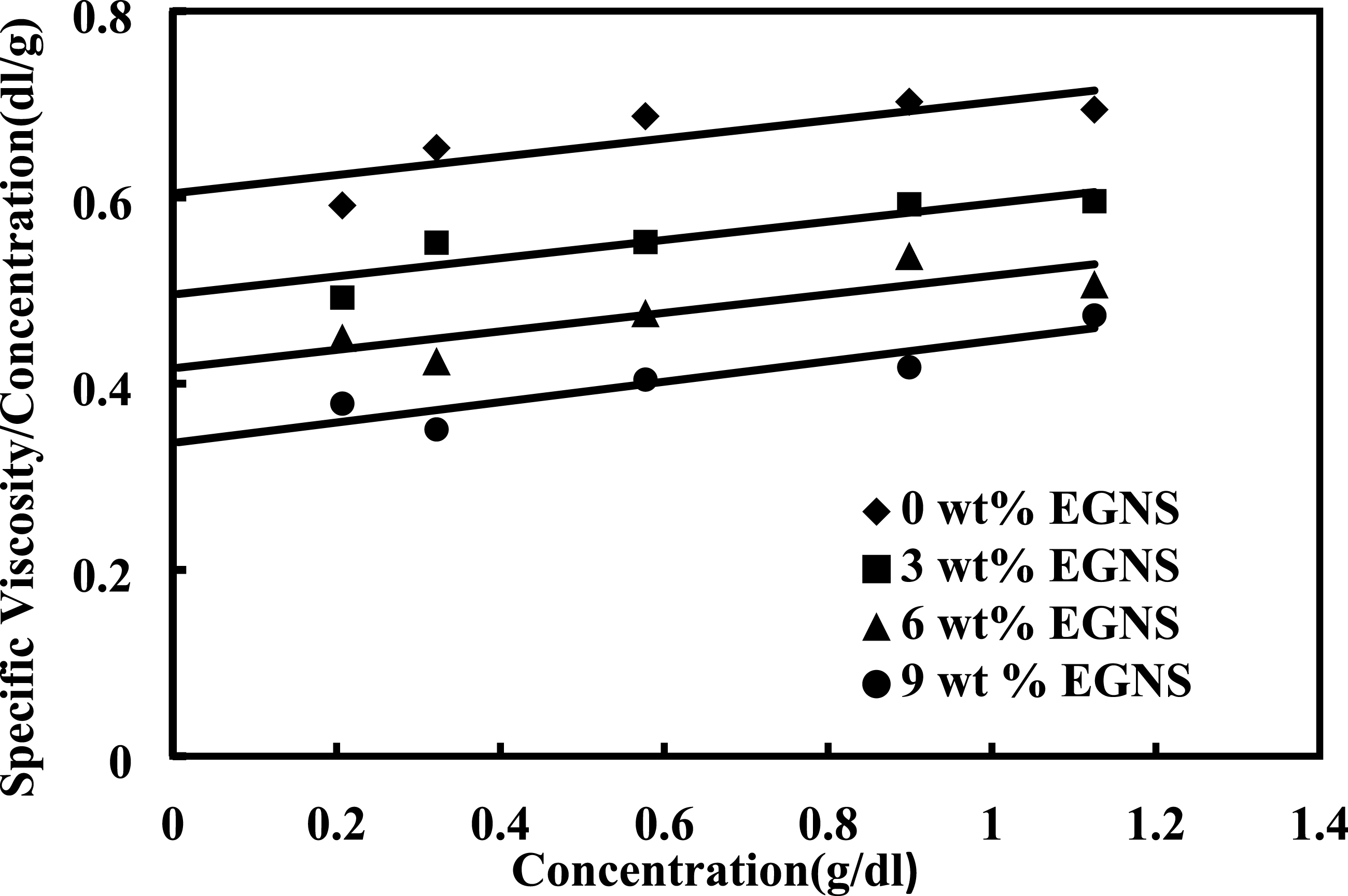
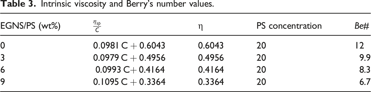
The fiber diameter result of each EGNS/PS/Solvent concentration has been related to the dimensionless parameter known as Berry’s number. The degree of molecular chain entanglement is calculated by Berry’s number which equals the product of EGNS/PS intrinsic viscosity by polystyrene concentration as the following equation:
Morphology of EGNS/PS nanofibers mats
Figure 3 shows the morphological characterization of EGNS at three different magnifications,50µ, 10µ, and 5µ as clearly lamellae. The images show that most of the EGNS is effectively exfoliated, resulting in ultrathin sheets with wrinkles and folds on the material’s surface. The interactions between the carbon structures and functional groups containing oxygen placed between the sheets and their edges cause the wrinkles and folds.43-45 Morphological of Exfoliated graphite nanosheets (EGNS) by SEM at different magnifications.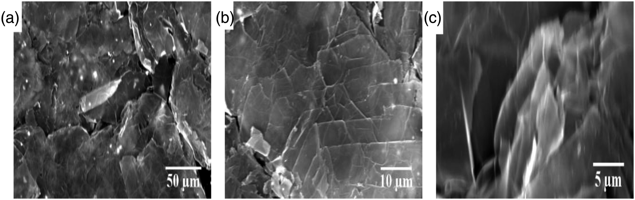
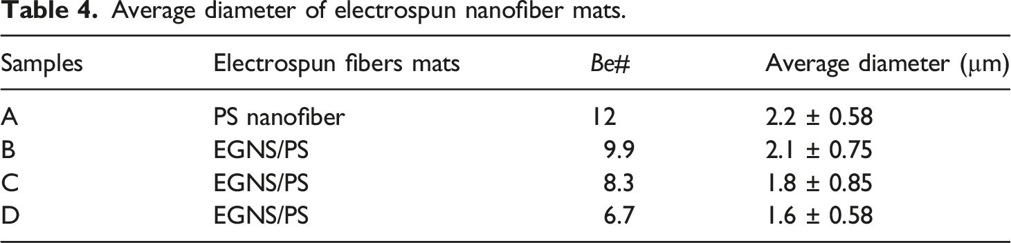
The morphology and diameter distribution of electrospun PS and EGNS/PS composite nanofiber mats are presented in Figures 4(a), (b), (c), (d). All of the fiber mats are randomly oriented and have a uniform distribution, as shown in the figures. In Figure 4(b) for the EGNS/PS 3 wt. % mats, Figure 4(c) for the EGNS/PS 6 wt. % mats, and Figure 4(d) for the EGNS/PS 9 wt. % mats. The surface of the composite nanofiber mats appeared to be a little rougher and wrinkled due to the presence of the filler apparent only at high concentration. Compared with electrospun PS (Figure 4(a)), EGNS/PS (Figures 4(b), (c), (d)) nanofibers displayed smaller diameters with the increasing amount of EGNS. Table 4 displays the computed average diameters of electrospun fibers. The presence of EGNS in the spin solution, which can increase the charge-carrying capacity of the solution, was attributed to the EGNS/PS composite’s small diameter. Further jet stretching produces smaller diameter fibers as a result of the solution’s increased charge-carrying capacity.
46
Furthermore, The rheological tests demonstrated that the viscosity of all materials including EGNS is lower than the viscosity of the pure matrix and that it decreases as the content of incorporated EGNS increases, which is consistent with the fiber diameter analysis.47,48 SEM image and diameter distribution of electrospun: (a) PS nanofiber; (b) EGNS/PS 3 wt.%; (c) EGNS/PS 6 wt.%; (d) EGNS/PS 9 wt.%. Average diameter of electrospun nanofiber mats.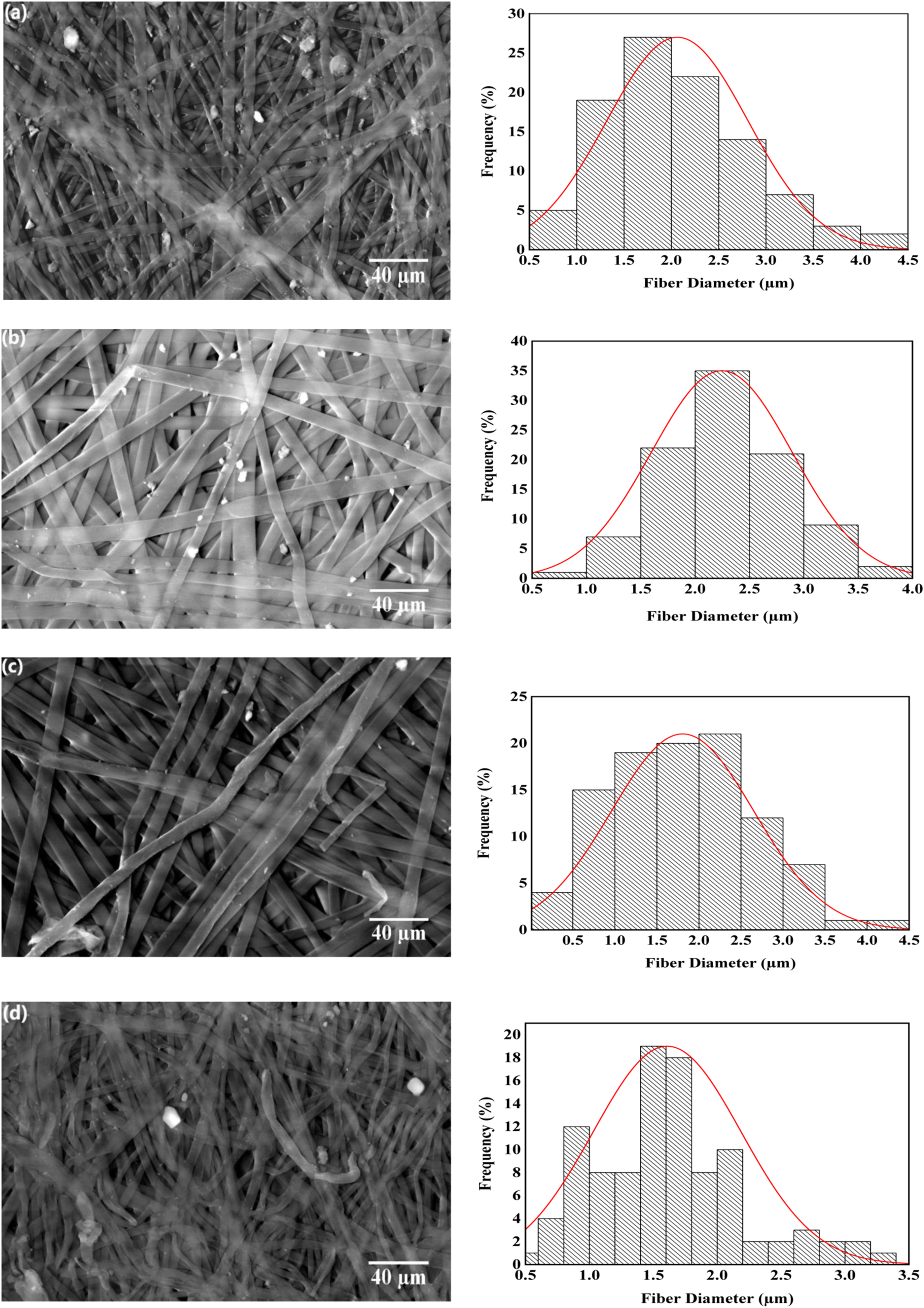
Mechanical properties
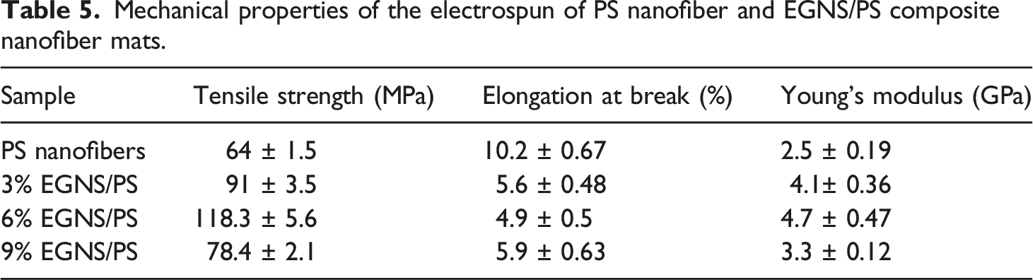
Figure 5 shows the stress-strain curves for PS and EGNS/PS composite nanofiber mats in tensile tests. The mechanical properties of the composites, such as Young’s modulus, ultimate tensile strength, and elongation at break, were significantly increased by increasing the concentration of EGNS up to 9 wt.% compared with PS nanofiber mats as shown in Table 5. All these properties, along with the better dispersion of EGNS in the polymer matrix, can lead to nanocomposites with superior mechanical properties.49,50 On the other hand, incorporation of nanofillers in the polymer matrix restricts polymer chain segmental mobility, which results in a considerable loss in ductility and a decreased elongation-at-break., as seen in Figure 5.
51
The ultimate tensile strength and Young’s modulus of cross-linked PS nanofiber mats were enhanced to 118.3 MPa and 4.7 GPa with the addition of 6 wt.% EGNS, which indicate 84% and 88% augmentation of tensile strength and Young’s modulus, respectively, compared with PS nanofibers. However, a substantial decrease in tensile strength and Young’s modulus was observed in 9 wt.% of EGNS. This may be due to EGNS aggregating together at higher concentrations. Agglomeration of EGNS would increase the size of the fillers, lowering the specific surface area for a given EGNS loading and reducing the stress transfer mechanism.
52
Stress-strain curves of the electrospun of PS nanofiber and EGNS/PS composite nanofiber mats. Mechanical properties of the electrospun of PS nanofiber and EGNS/PS composite nanofiber mats.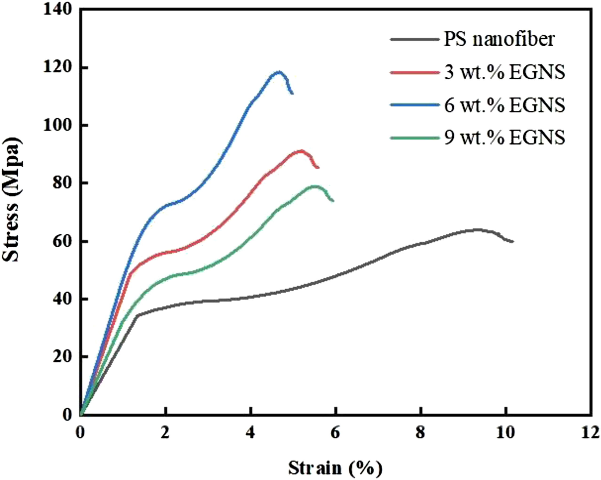
Thermal properties
DSC analysis of EGNS/PS electrospun mats
Figure 6 shows DSC thermograms of PS nanofiber and EGNS/PS electrospun composite nanofiber mats with various EGNS/PS concentrations. The glass transition temperature (Tg) is a macroscopic indicator of nanocomposites' relaxation behaviour, and its magnitude is based on multiple of structural factors. To quantify the changes in the Tgs of the samples, differential scanning calorimetry (DSC) measurements were performed. The systematic measurement of Tg for pure PS nanofiber is found to be 98°C and for EGNS/PS composite nanofiber mats is found to be 98°C for 3 wt.% EGNS, 118°C for 6 wt.% EGNS and 110°C for 9wt.% EGNS. The Tg of the EGNS/PS composites nanofiber mats increased significantly as the EGNS loading increased, due to the strong interaction between the EGNS and PS chains. Only 9wt.% EGNS, on the other hand, demonstrated a decrease in Tg due to its substantial free volume (void) resulting from excess EGNS aggregates and cause the segmental motions in the polymer network to increase.53,54 DSC thermogram of PS loaded with EGNS Composite nanofiber mats.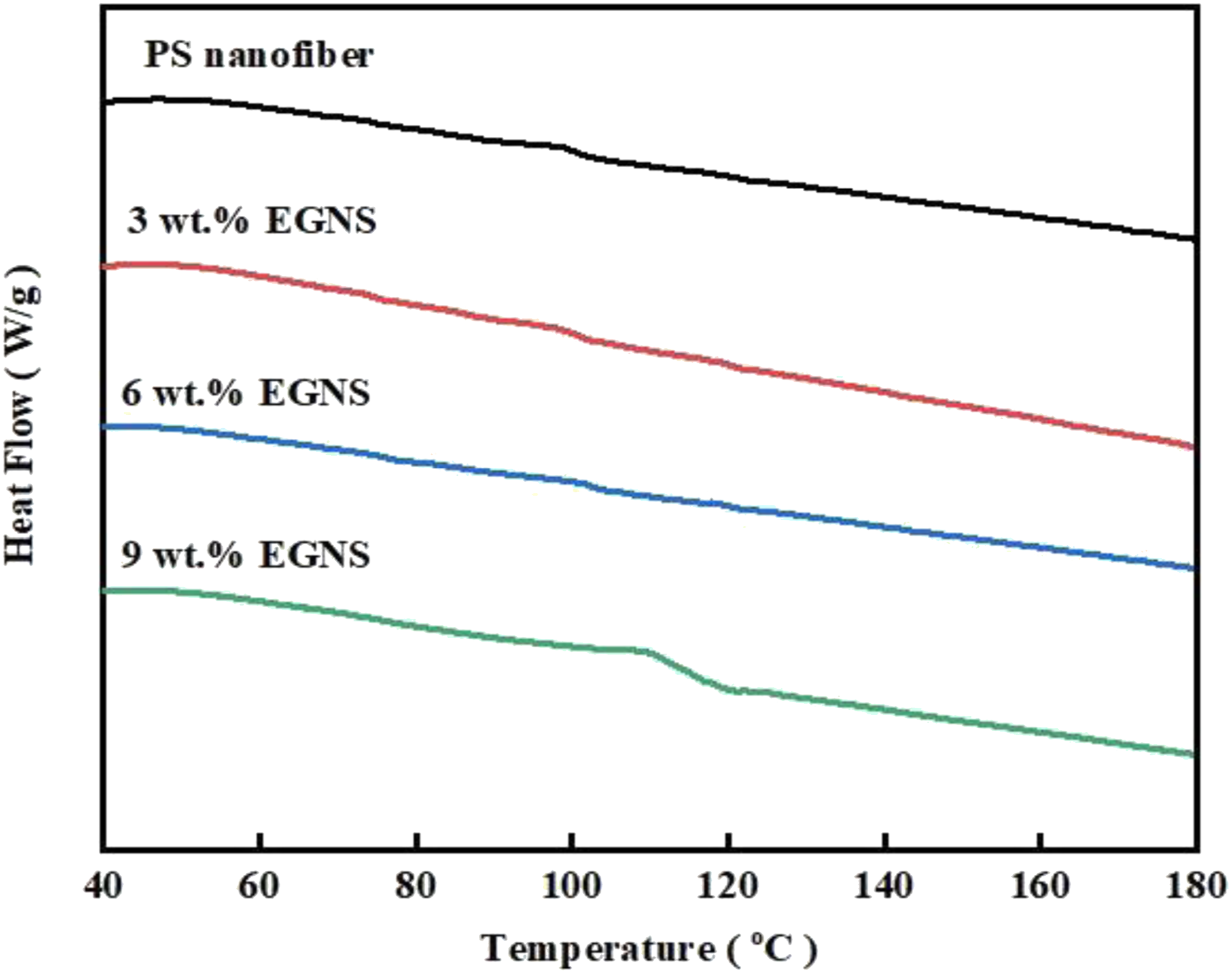
TGA analysis of EGNS/PS electrospun mats
TGA was used to investigate the thermal stability of PS nanofiber and EGNS/PS composite nanofiber mats as presented in Figure 7. As shown in TGA curves, major degradation temperature appeared above 400°C for all PS nanofiber and EGNS/PS Composite nanofiber mats occurred corresponding to pyrolysis. When EGNS is mixed with PS PS, the thermal strength of the EGNS/PS composite nanofiber mats is greatly improved above that of PS nanofiber mats. This is because EGNS improve molecular interaction, prevent polymeric bond motion, and increase the stiffness, energy required to move and break polymeric bonds, resulting in improved thermal characteristics of electrospun EGNS/PS composite nanofiber mats.55–56 As the EGNS content of the nanocomposites increased from 3 wt.% to 9 wt.%, the degradation temperature of the nanocomposites increased. The improved thermal stability of the EGNS/PS composite nanofiber mats, announce the high aspect ratio of the well-dispersed EGNS in the PS matrix, which prevents the generation of small thermally decomposed gaseous molecules. However, the thermal degradation moves to lower temperatures with higher EGNS (9 wt.%) compared with 3 wt.% and 6 wt.% loadings due to agglomeration of EGNS in the composite and a decrease in the physicochemical interaction between PS and EGNS.
57
TGA thermogram of of PS loaded with EGNS Composite nanofiber mats.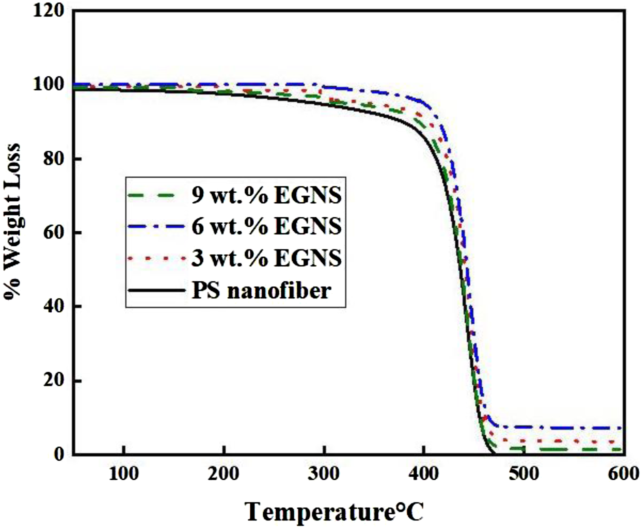
Raman spectroscopy analysis
Raman spectroscopy Studies on polystyrene nanofibers loaded with various concentrations of EGNS are presented in Figure 8. The PS nanofiber spectra showed two peaks at 841 and 1000 cm−1. As can be observed, the D band and G band are responsible for the two noticeable peaks that are displayed by EGNS and PS/EGNS at 1443 cm−1 and 1601 cm−1, respectively.58,59 These results indicate the presence of EGNS in the PS/EGNS composite nanofiber mats. Raman spectra of PS loaded with EGNS Composite nanofiber mats.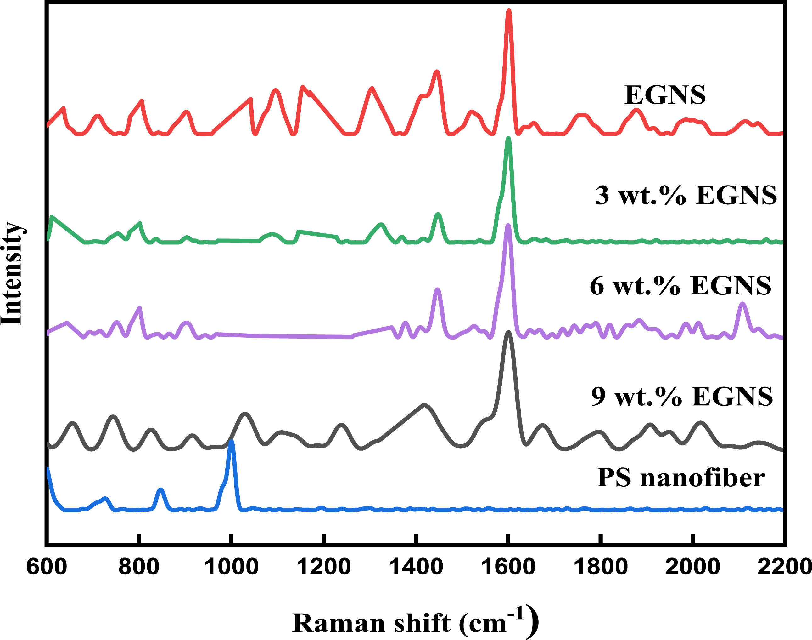
Conclusions
In this work, the electrospinning process has been successfully used to produce polystyrene (PS) loaded with various concentrations of EGNS composite nanofiber mats, and their morphological, mechanical, and thermal properties have been regularly investigated. The EGNS Reinforced PS Composite nanofiber mats have good dispersion, based on the SEM micrographs. The main conclusions and findings of this study can be summarized as follows: 1- The incorporation of various ratios of EGNS nanofibers rather than PS nanofibers greatly improved the mechanical properties. 2-An improvement of of 84% and 88% in tensile strength, young’s modulus respectively for the concentration of 6 wt.% of EGNS. 3- Thermal investigation revealed that all samples of EGNS/PS composite nanofiber mats had higher thermal stability than the PS nanofiber 4- Raman spectroscopy indicate the presence of EGNS in the PS/EGNS composite nanofiber mats. 5- EGNS/PS composite nanofiber mats with improved mechanical strength and thermal properties enhance their ability to fabricate high-performance thermal interface materials on a large scale. 6- The EGNS/PS nanocomposites fiber mats with improved mechanical and thermal stability were found to be useful for future applications in the biomedical, solar cell, electrical, and tissue engineering fields.
Footnotes
Declaration of conflicting interests
The author(s) declared no potential conflicts of interest with respect to the research, authorship, and/or publication of this article.
Funding
The author(s) received no financial support for the research, authorship, and/or publication of this article.