
Abstract
Background:
The relationship between the lateral femoral anatomic structures and femoral tunnel outlet according to changes in knee flexion and transverse drill angle during femoral tunnel creation in anterior cruciate ligament (ACL) reconstruction remains unclear.
Purpose:
To investigate the relationships between the lateral femoral anatomic structures and femoral tunnel outlet according to various knee flexion and transverse drill angles and to determine appropriate angles at which to minimize possible damage to the lateral femoral anatomic structures.
Study Design:
Controlled laboratory study.
Methods:
Simulation of ACL reconstruction was conducted using a 3-dimensional reconstructed knee model from the knees of 30 patients. Femoral tunnels were created using combinations of 4 knee flexion and 3 transverse drill angles. Distances between the femoral tunnel outlet and lateral femoral anatomic structures (minimum safe distance, 12 mm), tunnel length, and tunnel wall breakage were assessed.
Results:
Knee flexion and transverse drill angles independently affected distances between the femoral tunnel outlet and lateral femoral anatomic structures. As knee flexion angle increased, the distance to the lateral collateral ligament, lateral epicondyle, and popliteal tendon decreased, whereas the distance to the lateral head of the gastrocnemius increased (P < .001). As the transverse drill angle decreased, distances to all lateral femoral anatomic structures increased (P < .001). Considering safe distance, 120°, 130°, or 140° of knee flexion and maximum transverse drill angle (MTA) could damage the lateral collateral ligament; 130° or 140° of knee flexion and MTA could damage the lateral epicondyle; and 110° or 120° of knee flexion and MTA could damage the lateral head of the gastrocnemius. Tunnel wall breakage occurred under the conditions of MTA – 10° or MTA – 20° with 110° of knee flexion and MTA – 20° with 120° of knee flexion.
Conclusion:
Approximately 120° of knee flexion with MTA – 10° and 130° or 140° of knee flexion with MTA – 20° or MTA – 10° could be recommended to prevent damage to the lateral femoral anatomic structures, secure adequate tunnel length, and avoid tunnel wall breakage.
Clinical Relevance:
Knee flexion angle and transverse drill angle may affect femoral tunnel creation, but thorough studies are lacking. Our findings may help surgeons obtain a stable femoral tunnel while preventing damage to the lateral femoral anatomic structures.
Keywords
Anterior cruciate ligament (ACL) reconstruction is the treatment of choice for ACL injuries with instability. In this procedure, positioning of the femoral tunnel is considered a crucial factor for achieving successful surgical outcomes. In terms of femoral tunnel creation, biomechanical and clinical studies have been conducted to restore normal knee kinematics as well as improve rotational stability. 21,29 Anatomic ACL reconstruction via an outside-in or transportal technique, which seeks to place the femoral tunnel at the native ACL footprint, is widely used. 31 The transportal technique has an advantage over the outside-in technique in that no additional incision is required, but it also has the potential disadvantages of a short tunnel length and posterior tunnel wall breakage. 16 To overcome these shortcomings, a knee flexion angle >90° during femoral tunnel creation 3 and positioning of the accessory anteromedial portal as low as possible are recommended. 33
However, when the femoral tunnel is created under these conditions, the femoral tunnel outlet at the far cortex of the lateral femoral condyle is made more distal to that created with other femoral tunnel drilling techniques, thereby increasing the risk of damage to the lateral femoral anatomic structures. 28 A few cadaveric studies have noted the effects of knee flexion on the risk of iatrogenic injury to the lateral femoral anatomic structures when ACL reconstruction is performed using the transportal technique. 11,24,27 A recent clinical investigation also studied the relationship between the femoral tunnel outlet and lateral femoral anatomic structures according to changes in knee flexion angle during femoral tunnel creation. 9 That study’s authors proposed an appropriate range of knee flexion for creating a femoral tunnel to avoid possible damage to the lateral femoral anatomic structures. However, these studies 9,11,24,27 had limitations in that they addressed only knee flexion angle as an influencing factor in femoral tunnel creation. In addition to knee flexion angle, the transverse drill angle created in relation to the position of the accessory anteromedial portal is an important factor affecting femoral tunnel creation in ACL reconstruction using the transportal technique. 8,19 To the best of our knowledge, no comprehensive studies have been conducted to investigate the combined effect of the knee flexion and transverse drill angles on the relationship between the femoral tunnel outlet and lateral femoral anatomic structures.
Accordingly, this study sought (1) to investigate the relationship between the femoral tunnel outlet created by various knee flexion and transverse drill angles and lateral femoral anatomic structures, including the lateral collateral ligament, lateral epicondyle, popliteal tendon, and lateral head of the gastrocnemius and (2) to determine the appropriate knee flexion and transverse drill angles with which to minimize the likelihood of damaging the lateral femoral anatomic structures. This study was conducted using 3-dimensional (3D) computed tomography (CT) simulation.
Methods
Patients
After obtaining approval from the institutional review board of our hospital, we retrospectively reviewed the records of patients who underwent CT for assessment of knee injuries between January 2015 and December 2016. Patients who met the following inclusion criteria were included: (1) no fracture or osseous deformity of the femur or tibia, (2) no ligamentous injury of the knee, (3) no previous knee surgery, and (4) lower than grade 2 on the Kellgren-Lawrence osteoarthritis grading scale. 18 A total of 30 knees from 30 patients were included in the present study. Descriptive data of the included patients are provided in Appendix Table A1.
3D Reconstruction of CT Images
All CT examinations were performed through use of the CT scanner Sensation 64 (Siemens Healthcare). The tube parameters were 120 kVp and 135 to 253 mAs, the acquisition matrix was 512 × 512 pixels, the scan field of view was 134 to 271 mm, and the slice thickness was 0.6 to 1 mm. CT was performed with the knee in full extension. CT data in the Digital Imaging and Communication in Medicine format were obtained from the picture archiving and communication system (Centricity PACS; GE Medical System Information Technologies). Axial, coronal, and sagittal image data were imported into Mimics software (version 17; Materialise). A 3D knee model, including the femur and tibia without soft tissue, was then reconstructed.
Femoral Tunnel Drilling Simulation for the 3D CT Knee Model
The femoral center of the ACL footprint was determined as previously described. 13,19 The 3D-reconstructed femoral model was aligned in a true lateral position so that the lateral and medial femoral condyles were superimposed, as in the quadrant method developed by Bernard et al. 4 After the 3D knee model was placed at 90° of knee flexion, the medial femoral condyle was removed from the entire femoral model at the most anterior aspect of the intercondylar notch. A 4 × 4 grid was then drawn on the exposed medial wall of the lateral femoral condyle (Figure 1). The most anterior edge of the intercondylar notch on the 3D femoral model replaced the Blumensaat line used as a reference for grid alignment on a standard lateral radiograph. The femoral center of the ACL footprint was then determined by use of a previously described reference point. 32 The footprint center was located 28.4% off the posterior border along the line parallel to the Blumensaat line and 35.7% off the Blumensaat line along a line perpendicular to the Blumensaat line. After the center point of the ACL footprint was set, the split 3D model was restored to the entire original femoral model.

The quadrant method was used on a true medial view of the medial wall of the lateral femoral condyle in the 3-dimensional reconstructed femoral model to determine the center of the anterior cruciate ligament (ACL) footprint. The ACL footprint center (red dot) was placed 28.4% off the posterior border along a line parallel to the Blumensaat line and 35.7% off the Blumensaat line along a line perpendicular to the Blumensaat line.
To create a femoral tunnel, a total of 12 conditions were established, including 4 knee flexion angles and 3 transverse drill angles. The transepicondylar axis was set as the rotation axis for changing the knee flexion angle, 10 which was moved at intervals of 10° from 110° to 140° in consideration of the range of the flexion angle in the actual surgery mentioned in a previous study (Figure 2A). 9 The transverse drill angle was also set to 3 angles, as described in a previous study (Figure 2B). 19 The maximum drill angle was set to the angle that made the drill bit as close to the medial femoral condyle as possible without making contact therewith; this drill angle was defined as the maximum transverse drill angle (MTA). MTA – 10° and MTA – 20° were the other 2 drill angles set by moving the drill laterally 10° and 20° from the MTA, respectively. A simplified virtual cylinder replaced the drill bit. As described in a previous study, 19 the diameter of the cylinder was set to 8 mm, and the center of the virtual accessory anteromedial portal was located at 10 mm above the tibia plateau cortex, considering the medial meniscal thickness, tibial cartilage, and femoral tunnel radius. The 8–mm diameter cylinder entered the center of the ACL femoral footprint from the virtual accessory anteromedial portal, passing through the lateral femoral condyle, and exited the lateral aspect of the lateral femoral condyle. The center of the cylinder exit was marked as the center of the femoral tunnel outlet.

A total of 12 conditions were established to create a femoral tunnel, including 4 knee flexion angles and 3 transverse drill angles. (A) The knee flexion angle was changed at intervals of 10° from 110° to 140° on the transepicondylar axis. (B) The maximum transverse drill angle (MTA) was set as close as possible to the cartilage without making contact. MTA – 10° and MTA – 20° were determined by moving the drill laterally 10° and 20° from the MTA, respectively.
Measurement of Variables and Data Analysis
To evaluate the positional relationship between the center of the femoral tunnel outlet and the footprint centers of the lateral femoral anatomic structures, we used bony landmarks, including the lateral epicondyle, popliteal sulcus, and supracondylar process, as reference points, as described in a previous anatomic study. 20 The most prominent point of the lateral femoral condyle is the lateral epicondyle. The femoral footprint of the lateral collateral ligament is 1.4 mm proximal and 3.1 mm posterior to the lateral epicondyle. The femoral origin of the lateral head of the gastrocnemius located near the supracondylar process is 17.2 mm and 13.8 mm from the lateral epicondyle and the lateral collateral ligament, respectively. The femoral center of the popliteal tendon is at the most anterior one-fifth of the popliteal sulcus, 18.5 mm from the lateral collateral ligament (Figure 3A). The shortest straight distances between the center of the femoral tunnel outlet and the footprint center of the lateral femoral anatomic structures, including the lateral epicondyle, and the femoral origins of the lateral collateral ligament, popliteal tendon, and lateral head of the gastrocnemius were measured with the 3D reconstructed model (Figure 3B).

Measurement of the distances between the femoral tunnel outlet and the lateral femoral anatomic structures. (A) The footprint centers of the lateral femoral anatomic structures were determined using bony landmarks, including the lateral epicondyle, popliteal sulcus, and supracondylar process and the quantitative relationship between the lateral femoral anatomic structures. (B) The shortest distances between the center of the femoral tunnel outlet and footprint centers of the lateral femoral anatomic structures, including the lateral epicondyle and femoral origins of the lateral collateral ligament, popliteal tendon, and lateral head of the gastrocnemius, were measured.
The safe distance that prevented damage to the lateral femoral anatomic structures by the femoral tunnel outlet was estimated as the sum of the radii of the footprints of the lateral femoral anatomic structures and the femoral tunnel outlets. In a quantitative anatomic study with human cadaveric knee dissection, Godin et al 15 showed that the femoral attachment areas of the lateral femoral anatomic structures were 39.6 mm2 (range, 33.9-45.3 mm2) for the lateral collateral ligament, 59.1 mm2 (range, 48.4-69.9 mm2) for the lateral head of gastrocnemius, and 60.9 mm2 (range, 51.7-70.1 mm2) for the popliteal tendon. Drawing on that previous study, we calculated the maximum radii of each femoral footprint of the lateral head of the gastrocnemius, the popliteal tendon, and the lateral collateral ligament (4.7, 4.7, and 3.8 mm, respectively). Regarding the radius of the femoral tunnel outlet, unexpected accidental large-diameter breakage of the lateral femoral cortex by the femoral tunnel, which sometimes happens during femoral tunnel creation, was also considered in determining the safe distance. In such cases, the shape of the femoral tunnel outlet was elliptical, because the tunnel outlet was produced by the cylindrical tunnel penetrating the inclined lateral femoral cortex. We determined the maximum length of the radius within the femoral tunnel outlet by drawing a straight line between the center of the femoral tunnel outlet and the center of each lateral femoral anatomic structure. The length of the line located inside the femoral tunnel outlet was measured. The maximum length was 7.3 mm (mean, 4.8 mm; range, 4.0-7.3 mm). Accordingly, the sufficient minimum safe distance between the center of the femoral tunnel outlet and footprint centers of the lateral femoral anatomic structures was set to 12 mm, in accordance with the sum of the radii of the footprints of the lateral femoral anatomic structures and the femoral tunnel outlets. Lengths of the femoral tunnel and tunnel wall breakage were also assessed. Two orthopaedic surgeons measured variables, including the distance from the femoral tunnel outlet to the lateral femoral anatomic structures (lateral collateral ligament, lateral epicondyle, popliteal tendon, and lateral head of gastrocnemius) and the femoral tunnel length, without knowledge of the experimental condition to increase reliability. The mean of 2 measurements was used.
Statistical Analysis
To evaluate the effect of knee flexion and transverse drill angles on the distances from the femoral tunnel outlet to the lateral femoral anatomic structures, we used 2-way repeated-measures analysis of variance (ANOVA). For 2-way repeated-measures ANOVA, the normality of the data was confirmed by the Shapiro-Wilks test, and the sphericity of the data was tested by the Mauchly sphericity test. If the sphericity was not met, Greenhouse-Geisser correction was used to adjust for a lack of sphericity. After we determined the main effect of each factor and interaction effects of the factors, the Bonferroni test was performed for post hoc analysis to compare each condition of the combinations of knee flexion and transverse drill angle. The femoral tunnel length was analyzed in the same manner. The Cochran Q test was performed to compare the proportions of tunnel wall breakage between the groups. P < .05 was considered statistically significant. Statistical analyses were performed by use of IBM SPSS Statistics for Windows (Version 25.0; IBM), and statistical power was assessed using G*Power (Version 3.1). 12
Results
The distance between the footprint center of the lateral collateral ligament and the center of the femoral tunnel outlet increased as the knee flexion angle (P < .001) or transverse drill angle (P < .001) decreased (Table 1). The interaction effects of the knee flexion and transverse drill angles on this distance were not significant (P = .069). In the condition of fixed flexion angle, all pairwise comparisons between the distances according to each transverse drill angle showed significant differences (P < .05) (Figure 4A). In the condition of a fixed transverse drill angle, all pairwise comparisons between the distances according to each knee flexion angle also showed significant differences (P < .05), except when the knee flexion angle changed from 130° to 140° (Figure 4B). The results of the pairwise comparisons are provided in Appendix Tables A2 and A3. The statistical power regarding the distance between the lateral collateral ligament and femoral tunnel outlet calculated using G*Power 12 was 98.8%.
Effect of Knee Flexion and Transverse Drill Angles on the Distance to the Lateral Collateral Ligament a

a Distances (mm) are expressed as mean ± SD. P < .001 for the main effect of the transverse drill angle on the distance to the lateral collateral ligament. P < .001 for the main effect of knee flexion angle on the distance to the lateral collateral ligament. P = .069 for interaction effects between knee flexion and transverse drill angles on the distance to the lateral collateral ligament. MTA, maximum transverse drill angle.

(A) Pairwise comparisons between distances from the femoral tunnel outlet to the lateral collateral ligament according to each transverse drill angle in the condition of a fixed flexion angle. (B) Pairwise comparisons between distances from the femoral tunnel outlet to the lateral collateral ligament according to each knee flexion angle in the condition of a fixed transverse drill angle. Dotted lines represent a safe distance of 12 mm. *P < .05. dLCL, distance from the femoral tunnel outlet to the lateral collateral ligament; MTA, maximum transverse drill angle.
The distance between the footprint center of the lateral epicondyle and the center of the femoral tunnel outlet also increased as the knee flexion angle (P < .001) or transverse drill angles (P < .001) decreased (Table 2). The interaction effects of the knee flexion and transverse drill angles on this distance were not significant (P = .144). All pairwise comparisons between the distances in conditions of a fixed knee flexion or transverse drill angle showed significant differences (P < .05) (Figure 5). The results of the pairwise comparisons are provided in Appendix Tables A4 and A5.
Effects of Knee Flexion and Transverse Drill Angles on the Distance to the Lateral Epicondyle a

a Distances (mm) are expressed as mean ± SD. P < .001 for the main effects of transverse drill angles on the distance to the lateral epicondyle. P < .001 for the main effects of knee flexion angle on the distance to the lateral epicondyle. P = .144 for interaction effects between the knee flexion angle and transverse drill angle on the distance to the lateral epicondyle. MTA, maximum transverse drill angle.

(A) Pairwise comparisons between distances from the femoral tunnel outlet to the lateral epicondyle according to each transverse drill angle in the condition of a fixed flexion angle. (B) Pairwise comparisons of distances from the femoral tunnel outlet to the lateral epicondyle according to each knee flexion angle in the condition of a fixed transverse drill angle. Dotted lines represent a safe distance of 12 mm. *P < .05. dLE, distance from the femoral tunnel outlet to the lateral epicondyle; MTA, maximum transverse drill angle.
The distance between the footprint center of the lateral head of the gastrocnemius and center of the femoral tunnel outlet increased as the knee flexion angle increased (P < .001) or as the transverse drill angle decreased (P < .001) (Table 3). The interaction effects of the knee flexion and transverse drill angles on this distance were not significant (P = .096). All pairwise comparisons between the distances in the condition of a fixed knee flexion angle or transverse drill angle showed significant differences (P < .001) (Figure 6). The results of the pairwise comparisons are provided in Appendix Tables A6 and A7.
Effects of Knee Flexion and Transverse Drill Angles on the Distance to the Lateral Head of the Gastrocnemius a

a Distances (mm) are expressed as mean ± SD. P < .001 for the main effects of transverse drill angles on the distance to the lateral head of the gastrocnemius. P < .001 for the main effects of knee flexion angle on the distance to the lateral head of the gastrocnemius. P = .096 for interaction effects between knee flexion angle and transverse drill angle on the distance to the lateral head of the gastrocnemius. MTA, maximum transverse drill angle.

(A) Pairwise comparisons between distances from the femoral tunnel outlet to the lateral head of the gastrocnemius according to each transverse drill angle in the condition of a fixed flexion angle. (B) Pairwise comparisons between distances from the femoral tunnel outlet to the lateral head of the gastrocnemius according to each knee flexion angle in the condition of a fixed transverse drill angle. Dotted lines represent a safe distance of 12 mm. *P < .05. dLGT, distance from the femoral tunnel outlet to the lateral head of the gastrocnemius; MTA, maximum transverse drill angle.
The distance between the footprint center of the popliteal tendon and the center of the femoral tunnel outlet increased as knee flexion (P < .001) or transverse drill angles (P < .001) decreased (Table 4). The interaction effects of the knee flexion and transverse drill angles on this distance were not significant (P = .407). All pairwise comparisons between the distances in the condition of a fixed knee flexion or transverse drill angle showed significant differences (P < .05) (Figure 7). The results of the pairwise comparisons are provided in Appendix Tables A8 and A9.
Effects of Knee Flexion and Transverse Drill Angles on the Popliteal Tendon a
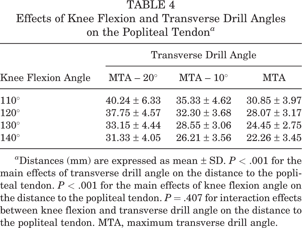
a Distances (mm) are expressed as mean ± SD. P < .001 for the main effects of transverse drill angle on the distance to the popliteal tendon. P < .001 for the main effects of knee flexion angle on the distance to the popliteal tendon. P = .407 for interaction effects between knee flexion and transverse drill angle on the distance to the popliteal tendon. MTA, maximum transverse drill angle.

(A) Pairwise comparisons between distances from the femoral tunnel outlet to the popliteal tendon according to each transverse drill angle in the condition of a fixed flexion angle. (B) Pairwise comparisons between distances from the femoral tunnel outlet to the popliteal tendon according to each knee flexion angle in the condition of a fixed transverse drill angle. Dotted lines represent a safe distance of 12 mm. *P < .05. dPLT, distance from the femoral tunnel outlet to the popliteal tendon; MTA, maximum transverse drill angle.
In consideration of the mean distance measuring less than the minimum safety distance of 12 mm, the combinations of knee flexion and transverse drill angle that could damage the lateral femoral anatomic structures were as follows: 120°, 130°, and 140° of knee flexion and MTA for the lateral collateral ligament; 130° and 140° of knee flexion and MTA for the lateral epicondyle; and 110° and 120° of knee flexion and MTA for the lateral head of the gastrocnemius. None of the combinations of knee flexion and transverse drill angles appeared to damage the insertion of the popliteal tendon in this study.
Both the flexion angle (P < .001) and the transverse drill angle (P < .001) had a significant effect on the tunnel length (Table 5). As knee flexion increased, the tunnel length also increased. Except for 110° of knee flexion, the tunnel length increased as the transverse drill angle decreased. The interaction effects of knee flexion and transverse drill angles on tunnel length were not significant (P = .065). Except for the conditions of MTA – 10° versus MTA (P = .581) and MTA – 20° versus MTA (P = .174) at 110° of knee flexion, all other pairwise comparisons in a fixed knee flexion angle showed significant differences (P < .05) (Figure 8A). All pairwise comparisons in the condition of a fixed transverse drill angle showed significant differences (P < .05) (Figure 8B). The results of the pairwise comparisons are provided in Appendix Tables A10 and A11.
Effects of Knee Flexion and Transverse Drill Angles on the Tunnel Length a
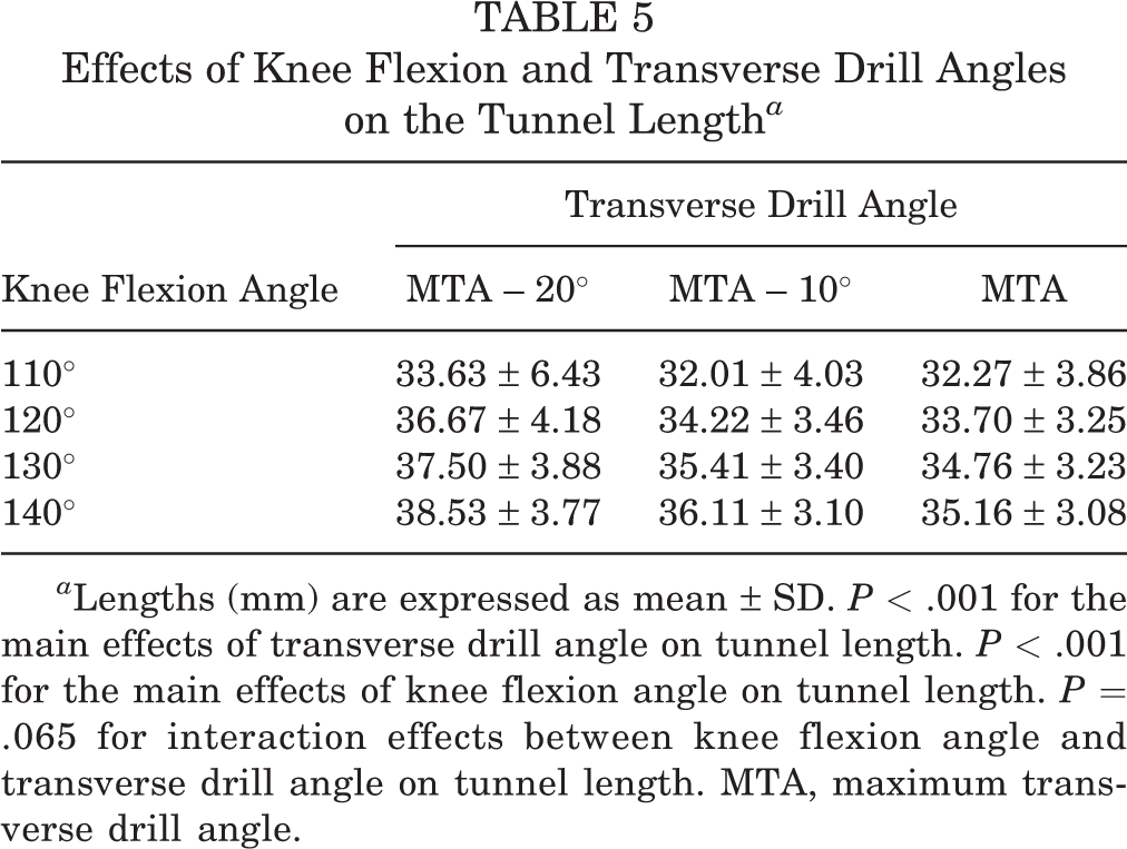
a Lengths (mm) are expressed as mean ± SD. P < .001 for the main effects of transverse drill angle on tunnel length. P < .001 for the main effects of knee flexion angle on tunnel length. P = .065 for interaction effects between knee flexion angle and transverse drill angle on tunnel length. MTA, maximum transverse drill angle.

(A) Pairwise comparisons between tunnel lengths according to each transverse drill angle in the condition of a fixed flexion angle. (B) Pairwise comparisons between tunnel lengths according to each knee flexion angle in the condition of a fixed transverse drill angle. *P < .05. MTA, maximum transverse drill angle.
Tunnel wall breakage occurred under the following conditions: MTA – 20° and MTA – 10° at 110° of knee flexion and MTA – 20° at 120° of knee flexion. No breakage was observed in the other conditions. The proportions of tunnel wall breakage with varying knee flexion angles differed significantly at MTA – 20° (P < .001) and MTA – 10° (P = .002). The proportions of tunnel wall breakage with varying transverse drill angles differed significantly with 110° of flexion (P < .001) (Table 6).
Comparison of Proportions of the Femoral Tunnel Wall Breakage a
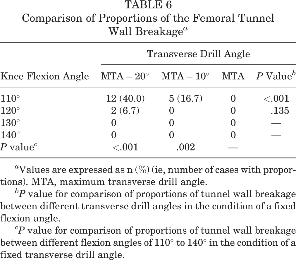
a Values are expressed as n (%) (ie, number of cases with proportions). MTA, maximum transverse drill angle.
bP value for comparison of proportions of tunnel wall breakage between different transverse drill angles in the condition of a fixed flexion angle.
cP value for comparison of proportions of tunnel wall breakage between different flexion angles of 110° to 140° in the condition of a fixed transverse drill angle.
Discussion
Various factors related to femoral tunnel characteristics, such as tunnel length and tunnel wall breakage, can affect the surgical outcomes of ACL reconstruction. 1,2,6,14 However, few researchers have studied iatrogenic injuries to the lateral femoral anatomic structures. The exit of the femoral tunnel at the lateral femoral cortex when the transportal technique is used tends to move more distally, compared with a femoral tunnel created using the transtibial technique. 28 This results in the femoral tunnel outlet being located closer to the lateral femoral anatomic structures, thereby increasing the risk of damage thereto. 11,24,25,27 In addition, the relationship between the femoral tunnel outlet and lateral femoral anatomic structures has other critical implications, such as stable fixation of the suspensory fixation device achieved by secure settlement on a bony structure, not on a soft tissue structure, 7,22,26,30 and intertunnel relationships in multiligament reconstruction. 5,23 According to the results of the present study, the distances between the center of the femoral tunnel outlet and footprint centers of the lateral collateral ligament, lateral epicondyle, and popliteal tendon increased as the knee flexion angle or transverse drill angles decreased. The distance between the center of the femoral tunnel outlet and footprint center of the lateral head of the gastrocnemius increased as knee flexion angle increased or transverse drill angle decreased. The knee flexion angle and transverse drill angle independently affected the distance between the femoral tunnel outlet and footprints of the lateral femoral anatomic structures without any interaction effects.
The femoral tunnel outlet moved closer to the lateral collateral ligament, lateral epicondyle, and popliteal tendon and away from the lateral head of the gastrocnemius as the knee flexion angle increased during the femoral tunnel creation. Some experimental studies have demonstrated the effect of knee flexion on the distance between the femoral tunnel outlet and footprints of the lateral femoral anatomic structures. 11,24,27 In a cadaveric study, Nakamae et al 24 investigated the relationship between the femoral tunnel outlet and lateral collateral ligament and lateral head of the gastrocnemius when performing double-bundle ACL reconstruction with a fixed transverse drill angle through an accessory anteromedial portal placed 2.5 cm medial to the medial border of the patellar tendon. Their analysis showed that the femoral exit of a guidewire moved closer to the lateral collateral ligament and away from the lateral head of the gastrocnemius as knee flexion increased from 90° to 130° at an interval of 20°. Another cadaveric study 11 of double-bundle ACL reconstruction noted that increasing the knee flexion angle influenced the femoral tunnel outlet by causing it to converge closer to the lateral collateral ligament, whereas decreasing the knee flexion angle placed the femoral tunnel outlet closer to the lateral head of the gastrocnemius. A previous virtual 3D simulation study 27 compared 120° and 135° of knee flexion in creating the femoral tunnel and demonstrated that the femoral tunnel outlet moved anteriorly and distally with increasing the flexion angle in double-bundle ACL reconstruction. Only a few clinical studies have been conducted on actual patients, however. One clinical study 9 of single-bundle ACL reconstruction using the transportal technique with an MTA noted that the femoral tunnel moved closer to the lateral collateral ligament, lateral epicondyle, and popliteal tendon and away from the lateral head of the gastrocnemius as knee flexion increased. The authors recommended a knee flexion angle ranging from 121° to 131° to achieve the lowest likelihood of injury to the lateral femoral anatomic structures in creating femoral tunnels. The results of our 3D CT simulation study, which addressed a wider range of knee flexion angles, are consistent with those of previous studies in terms of the effect of knee flexion angle on the distance to the lateral femoral anatomic structures.
The importance of our study is that we also analyzed the effects of variation in transverse drill angle. As the transverse drill angle decreased, the femoral tunnel outlet moved away from all lateral femoral anatomic structures, including the lateral collateral ligament, lateral epicondyle, lateral head of the gastrocnemius, and popliteal tendon. According to previous studies, alteration of the transverse drill angle changes the trajectory of the femoral tunnel, leading to variations in the characteristics of the femoral tunnel. 17,19,27 Kim et al 19 found that femoral tunnel characteristics, such as tunnel length, posterior wall blowout, and graft bending angle, were influenced by changes in the transverse drill angle. Hensler et al 17 demonstrated that the transverse drill angle affected the morphology of the femoral tunnel aperture when a 3D CT model was used. Only a few previous studies have been conducted on the relationship between the transverse drill angle and femoral tunnel outlet. Osaki et al 27 compared the locations of the femoral tunnel outlets according to changes in the portal position for femoral tunnel creation. They compared 3 portal locations, including the standard anteromedial portal, far medial and low portal, and far medial and high portal, and showed that lowering the drilling portal moved the femoral tunnel outlet anteriorly and distally, whereas medialization of the portal moved it posteriorly and distally. However, those investigators did not assess the effects on the femoral tunnel outlets according to horizontal movement of an accessory anteromedial portal, which is more clinically useful, and they did not specify the quantitative relationship between the femoral tunnel outlet and lateral femoral anatomic structures. The present study demonstrated changes in the distances between the femoral tunnel outlet and lateral femoral anatomic structures according to changes in the transverse drill angle, and it could be recommended to create femoral tunnels at a smaller transverse drill angle to prevent damage to the lateral femoral anatomic structures. In actual surgery, the drill bit can be attached to the cartilage of the medial femoral condyle as much as possible without making contact therewith to set the MTA position, and the angle for inserting the drill bit can be controlled by moving it laterally from the position at MTA.
In addition to the safety of the lateral femoral anatomic structures, tunnel length and tunnel wall breakage must be considered comprehensively to determine appropriate conditions for femoral tunnel creation. Regarding damage to the lateral femoral anatomic structures considering the safety distance of 12 mm, the present study showed that 120°, 130°, and 140° of knee flexion with the MTA were associated with an increased risk of damage to the lateral collateral ligament and that 110° or 120° of knee flexion with the MTA might endanger the lateral head of the gastrocnemius. The footprint of the popliteal tendon was not endangered in any combination of knee flexion and transverse drill angles. In cases using soft tissue grafts, such as a hamstring graft, secured with a suspensory fixation device for femoral tunnel fixation, sufficient length of the femoral tunnel is needed. A femoral tunnel length of <25 mm is considered short. 2 Because the mean femoral tunnel lengths in this study were >30 mm in all combinations of knee flexion and transverse drill angles, a short tunnel was not encountered in this study. However, in consideration of tunnel wall breakage, more than 1 case of breakage was found at 110° or 120° of knee flexion with MTA – 20° and 110° of knee flexion with MTA – 10°. Thus, the safe conditions for the combination of the knee flexion and transverse drill angles were 120° of knee flexion with MTA – 10° and 130° or 140° of knee flexion with MTA – 20° or MTA – 10°, when all variables, including tunnel length, tunnel wall breakage, and damage to the lateral femoral anatomic structures, were taken into consideration comprehensively. At a knee flexion angle ≥120°, positioning the drill slightly off the cartilage of the medial femoral condyle would create a stable tunnel without damaging the lateral femoral anatomic structures. Changing only the knee flexion angles addressed in a previous clinical study 9 could be limited in determining the condition of femoral tunnel creation to prevent damage to the lateral femoral anatomic structures, and varying the transverse drill angle, in addition to the knee flexion angle, can help create a safe and stable femoral tunnel over a wider range of conditions. The results of this study are applicable to ACL reconstruction using a transportal technique. To reduce the risk of damage to the lateral femoral anatomic structures, or in patients who undergo multiligament reconstruction for ACL and lateral femoral structures, the outside-in technique could provide an alternative because this technique makes it easier to adjust the insertion position of the guide pin for the femoral tunnel at the lateral femoral cortex.
Several limitations must be considered before drawing more definite conclusions from this study. First, this study was conducted using a 3D-reconstructed knee model from CT. Knee flexion was changed on the transepicondylar axis, as described in a previous study. 10 However, additional knee kinematic factors during flexion movements, such as screw home movement and femoral rollback, were not considered. The virtual accessory anteromedial portal was placed considering the thickness of the meniscus and cartilage of the tibia. However, there could be differences in actual cases. Accordingly, a clinical study on actual patients is needed to add clinical significance to the results of the present study. Second, bony landmarks and the quantitative relationship between the lateral femoral anatomic structures were used to determine the locations of the lateral femoral anatomic structures, as described in a previous anatomic study. 20 Some individual variations could occur, even though quantitative data regarding the relationship between the lateral femoral anatomic structures were based on solid anatomic evidence. Third, the tendon itself can be damaged depending on its path, although even with direct damage to the tendon, the extent of damage is less than that to the attachment footprint of the bone. Because the tendon itself was not reconstructed in 3D and the paths of the lateral femoral anatomic structures were not visible, damage to soft tissue could not be investigated. A study using 3D reconstruction from magnetic resonance images, including soft tissue reconstruction, is needed to draw a more solid conclusion. Fourth, it is not known exactly how harmful it is when a part of the footprint of the lateral femoral anatomic structure is damaged, because the present study was a 3D simulation study. The effect of damage to the lateral femoral anatomic structures on the clinical outcome was not assessed. A clinical study on actual patients may be needed to determine how much damage to the footprint of the lateral femoral anatomic structure affects the clinical outcome. Fifth, the present study assessed the distance between the center of the femoral tunnel outlet and footprint centers of the lateral femoral anatomic structures, femoral tunnel length, and tunnel wall breakage as variables related to the characteristics of the femoral tunnel. However, there could be more variables affecting the characteristics of the femoral tunnel, such as graft bending angle. 19 A comprehensive study that examines more variables is needed to reach a more solid conclusion.
Conclusion
The knee flexion angle and transverse drill angle independently affected the distance between the center of the femoral tunnel outlet and footprint centers of the lateral femoral anatomic structures. The distance from the femoral tunnel outlet to the lateral collateral ligament, lateral epicondyle, and popliteal tendon decreased, whereas the distance to the lateral head of the gastrocnemius increased as the knee flexion angle increased. As the transverse drill angle decreased, the distance from the femoral tunnel outlet to all lateral femoral anatomic structures increased. Approximately 120° of knee flexion with MTA – 10° and 130° or 140° of knee flexion with MTA – 20° or MTA – 10° could be recommended to prevent damage to the lateral femoral anatomic structures, secure adequate tunnel length, and avoid tunnel wall breakage.
Footnotes
Acknowledgment
We thank orthopaedic surgeons Jai Hyun Chung and Kyung-Han Lim for their assistance in measurement of variables.
Final revision submitted March 28, 2020; accepted April 13, 2020.
One or more of the authors has declared the following potential conflict of interest or source of funding: This study was supported by a grant from the Chong Kun Dang Pharmaceutical Corp through the University-Industry Foundation, Yonsei University Health System (grant 2017-31-0622). AOSSM checks author disclosures against the Open Payments Database (OPD). AOSSM has not conducted an independent investigation on the OPD and disclaims any liability or responsibility relating thereto.
Ethical approval for this study was obtained from Severance Hospital, Yonsei University College of Medicine (ref No. 4-2019-0780).
Appendix
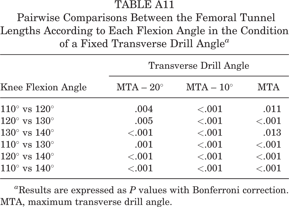
Pairwise Comparisons Between the Femoral Tunnel Lengths According to Each Flexion Angle in the Condition of a Fixed Transverse Drill Angle a
| Transverse Drill Angle | |||
|---|---|---|---|
| Knee Flexion Angle | MTA – 20° | MTA – 10° | MTA |
| 110° vs 120° | .004 | <.001 | .011 |
| 120° vs 130° | .005 | <.001 | <.001 |
| 130° vs 140° | <.001 | <.001 | .013 |
| 110° vs 130° | .001 | <.001 | <.001 |
| 120° vs 140° | <.001 | <.001 | <.001 |
| 110° vs 140° | <.001 | <.001 | <.001 |
a Results are expressed as P values with Bonferroni correction. MTA, maximum transverse drill angle.