
Abstract
Background:
It is common to place the posterior cruciate ligament (PCL) tibial tunnel with a transtibial technique using a guide that attempts to place the center of the tunnel 1 to 1.5 cm distal to the tibiofemoral joint. It is unknown how well this technique will re-create the native tibial footprint of the PCL.
Purpose:
To evaluate the accuracy of tibial tunnel placement using a transtibial technique.
Study Design:
Controlled laboratory study.
Methods:
Ten cadaveric knees from 10 donors underwent arthroscopic transtibial drilling of the tibial tunnel with use of a posteromedial portal for visualization. The transtibial guide was rested flush against the tibial spines to allow for the guide to be as distal as possible, which was between 1 and 1.5 cm distal to the tibiofemoral joint line. Using this technique, an attempt was made to place the tibial tunnels as close to the center of the PCL footprint as possible. All knees underwent computed tomography both pre- and postoperatively with a previously reported technique optimized for ligament evaluation. This allowed comparison of the anatomic PCL tibial footprint to the tibial tunnel aperture. The percentage of tunnel aperture contained within the native footprint as well as the distance from the center of the tunnel aperture to the center of the footprint was measured.
Results:
The percentage of tunnel aperture contained within the native footprint was 45.9% ± 23.1%. The distance from the center of the tibial tunnel aperture to the center of the tibial PCL footprint was 6.4 ± 2.3 mm. The tunnels were almost always (9/10) distal (or inferior) to the native footprint and either slightly lateral (5/10) or centered (5/10) in a medial to lateral direction.
Conclusion:
This study demonstrates that using the transtibial drilling technique in the tibia for PCL reconstruction places approximately half of the tibial tunnel aperture within the tibial footprint. Generally, the tunnel is distal to the footprint.
Clinical Relevance:
Consideration should be given to the fact that, using this transtibial technique, the tibial tunnel aperture is generally not placed in the center of the footprint. This may not be a negative issue, however, since there are other potential advantages from distal tunnel placement.
Reconstruction techniques following posterior cruciate ligament (PCL) rupture have been evolving as indications for surgery have become better defined. 4,29 On the tibial side, there are many ways of performing the reconstruction, including a transtibial tunnel, open tibial inlay, and arthroscopic tibial inlay. 17,27 To date, one of the most commonly used techniques is the transtibial approach, and overall good outcomes using this technique with various femoral tunnel techniques have been reported. 13,20 –22 The goal in any PCL reconstruction is to re-create the normal anatomy as closely as possible to restore the normal function and mechanics of the PCL. 6 It is not known how well the transtibial technique re-creates the anatomy of the PCL tibial footprint. The purpose of this study, therefore, was to compare the tibial tunnel aperture in the transtibial technique with the native PCL tibial footprint in order to assess how well the new graft is placed in the center of the native anatomy.
Methods
Ten fresh frozen cadaveric knees from 10 separate donors (9 males, 1 female) were used for the study, with a mean age of 75.8 ± 11.5 years. There was equal representation of right and left knees, and the sides were randomly selected during tunnel preparation.
Computed Tomography Technique and Image Processing
Prior to any intervention, all knees underwent dual energy computed tomography (CT) scanning in a dual energy scanner (Siemens SOMATOM Definition; Siemens, Erlangen, Germany) using a technique optimized for ligament evaluation in a cadaver. After each knee had undergone transtibial tunnel drilling, they were rescanned. Commercially available third-party software (iNtuition; TeraRecon, Foster City, California, USA) was then used for image processing. The software is approved by the Food and Drug Administration and the tools are considered precise and accurate as they are based on universal DICOM (Digital Imaging and Communications in Medicine) clinical image standards. The software has been used for similar applications in previous orthopaedic publications. 23,24 On the preintervention scans, sagittal reformats created from the 80-keV soft tissue algorithm axial data set were used to identify the PCL footprint (Figure 1). A line running from the anterior to the posterior extent of the PCL tibial attachment on the PCL facet was marked on each 0.625-mm sagittal slice through consensus of an orthopaedic surgeon and a musculoskeletal radiologist, while cross-referencing the axial and coronal images for guidance when needed. Applying the multiplanar reformatting tool, we created images oriented in an oblique axial plane parallel to the bony surface at the PCL tibial attachment, thus placing as many sagittal markings in one image as possible. The software was then used to fuse the marked preintervention with the postintervention CT scans, and the native tibial PCL footprint and the tibial tunnel aperture were both labeled circumferentially. This allowed anatomic comparison of the PCL footprint to the drill tunnel aperture (Figure 2). It should be noted that these are not conventional CT scan parameters, and the radiation dose would not be acceptable in live persons.

Sagittal computed tomography (CT) image demonstrating the technique for marking the tibial attachment of the posterior cruciate ligament (PCL) in a study cadaver. The high-dose 80-keV soft tissue scan algorithm allows for confident and accurate identification of the PCL footprint. The PCL (white arrows) is seen discretely. The black line represents the marking placed on each sagittal CT image where PCL fibers attach to the tibia. The black arrows represent the anterior and posterior extent of the PCL footprint.

Fusion image from transtibial drilling demonstrating the combined data from the preoperative and postoperative computed tomography scans as well as the consensus manual labeling of the posterior cruciate ligament (PCL) tibial footprint. The red outline represents the tibial footprint, while the green outline represents the tunnel aperture. The overlap of these outlines was used to calculate the percentage of tunnel aperture within each footprint. Straight lines were used to identify the center of each outline, and center points were used to measure the distance between the footprint and aperture. In addition, the center points were used to describe the direction of orientation of the tunnel aperture relative to the footprint; the aperture is nearly directly distal in this case.
The percentage of tunnel aperture contained within the native footprint was measured. In addition, the distance from the center of the tunnel aperture to the center of the footprint was measured. The center points of both the footprint and tunnel aperture were identified by placing 1 horizontal and 1 vertical line within each outlined area. Each line equally divided the area of either the footprint or aperture; the intersection of the lines therefore represented the center point (Figure 2). The center points were also used to identify the direction of the center of the tunnel aperture in relation to the center of the native footprint (Figure 2). Finally, footprint surface area was noted, allowing us to confirm consistency of the measurements with previously reported surface areas of the PCL tibial footprint.
Reconstruction Technique
Standard medial and lateral parapatellar arthroscopic portals were created. The proximal portion of the PCL was debrided using a shaver until it was possible to visually place a posteromedial portal. The arthroscope and shaver were interchanged through the anterior portals and the posteromedial portal until the PCL was debrided to a cuff of tissue on the tibia. Care was taken to preserve the entire footprint for visualization of the footprint during drilling. A Smith & Nephew Endoscopy Acufex external tibial tunnel drill guide (Andover, Massachusetts, USA) set at 60° was then advanced into the joint. The guide was set as flush against the tibial spines as possible to allow the tip of the guide to reach as distal on the tibia as possible (Figure 3). In all specimens, this measured 1 to 1.5 cm distal to the joint line. 7,13,21,25,26 Under direct visualization with the arthroscope in the posteromedial portal, the tip of the guide was centered in the footprint in a medial to lateral direction. To further enhance the medial to lateral centering, the mamillary bodies were also used as tactile feedback using the tip of the guide. The guide pin was then drilled transtibial with a starting point on the anteromedial tibia between the anterior fibers of the MCL and the tibial tubercle while avoiding the pes anserinus (Figure 4). A 10-mm tunnel was drilled over the guide wire using a barrel reamer. This was all accomplished with the knee in approximately 90° of flexion.
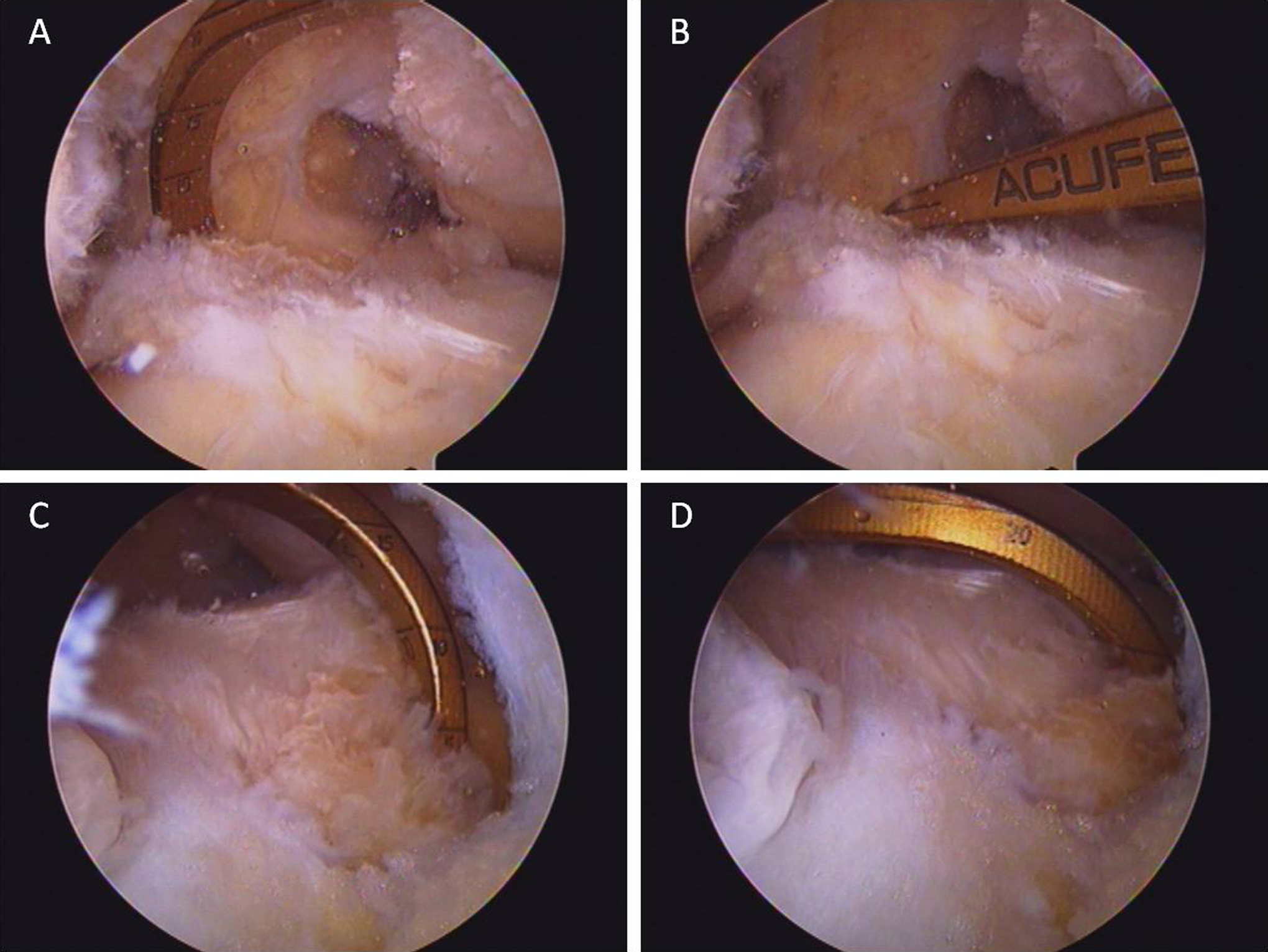
View from the lateral parapatellar portal guide through medial parapatellar portal at (A) initial entry and (B) once it is fully seated distally against the tibial spines. View from the posteromedial portal guide through medial parapatellar portal at (C) initial entry and (D) once it is fully seated distally against the tibial spines.
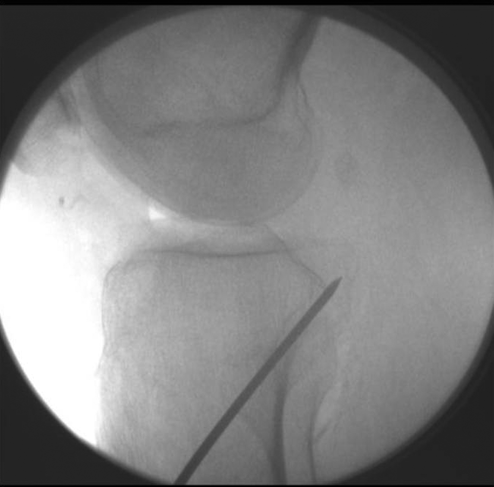
Lateral radiograph demonstrating placement of the guide pin using this technique. The pin exits at the posterior and distal–most aspect of the posterior cruciate ligament (PCL) tibial facet.
Results
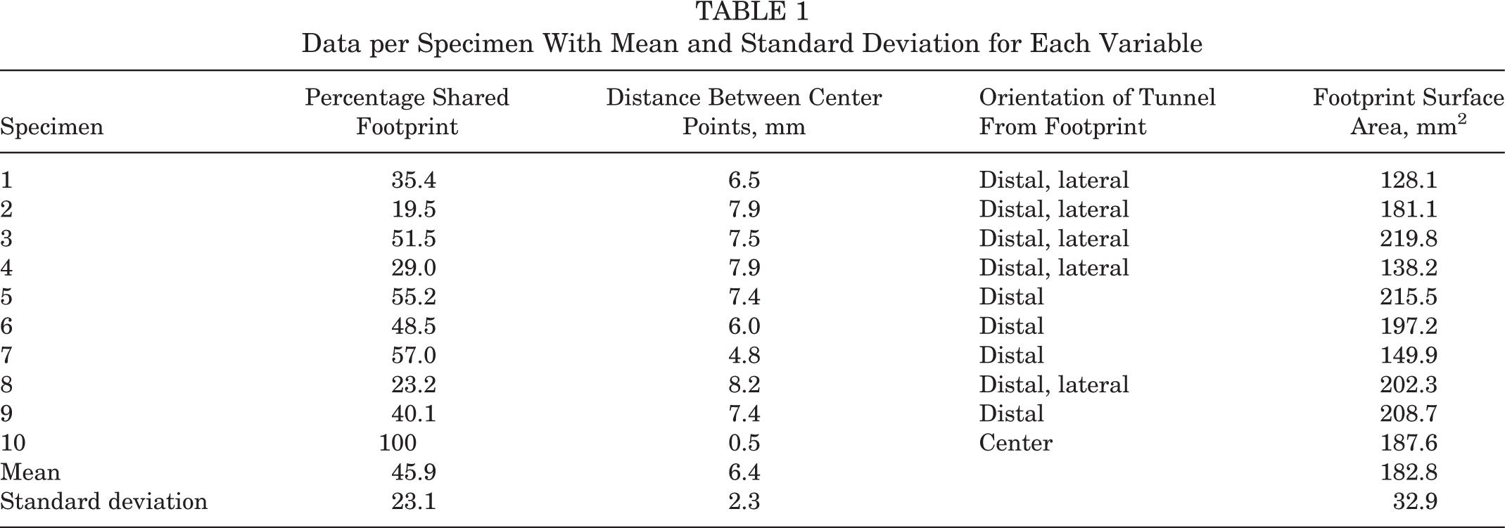
Results are summarized in Table 1. The percentage of the tunnel aperture placed within the native footprint was 45.9% ± 23.1%. The distance from the center of the tibial tunnel aperture to the center of the tibial PCL footprint was 6.4 ± 2.3 mm. The tunnels were almost always (9/10) distal (or inferior) to the native footprint and either slightly lateral (5/10) or centered (5/10) in a medial to lateral direction. The native PCL footprint surface area was 182.8 ± 32.9 mm2.
Data per Specimen With Mean and Standard Deviation for Each Variable
Discussion
Results from this study indicate that transtibial drilling places roughly half of the tibial tunnel aperture within the native tibial PCL footprint. If not centered within the footprint, the tunnel is likely to be distal and sometimes slightly lateral to the native footprint. The mean surface area for the PCL footprint was found to be nearly 183.9 mm2.
The anatomic parameters of the tibial PCL attachment were first described by Girgis et al 9 in 1975. Partially based on their descriptions, many subsequent authors have suggested placing the tibial PCL tunnel 1 to 1.5 cm distal to the tibiofemoral joint line. 7,13,21,25,26 The results from this study, however, would suggest that this approach does not place the tunnel aperture in a perfectly anatomic position. This is also consistent with a more recent anatomic study suggesting that the center of the PCL tibial attachment is only a couple millimeters below the tibiofemoral joint line. 12 Given the nonanatomic tunnel placement, one might see this transtibial technique in a negative light; however, there are other issues that are important to consider, particularly when the tunnel is distal to the footprint.
Intuitively, it makes sense for the graft to be in an anatomic location, but it is unclear that a nonanatomic location for the tunnel has a negative effect on the PCL graft or, ultimately, on PCL function. Rather, choosing the location of the tibial tunnel may be seen as a set of competing trade-offs between anatomic and nonanatomic. It is felt that placing the tibial tunnel within the anatomic footprint can result in the graft being subjected to the “killer turn” first described by Berg. 2 Methods of avoiding the sharp turn in the tunnel have been described, including smoothing of the tunnel and remnant preservation, but it is unclear what impact these may have on the overall healing and function of the graft. 1,28 Other authors have described the tibial inlay technique to avoid the turn encountered with a tibial tunnel, but tibial inlay has its own set of drawbacks. 3,16 One suggestion for minimizing the turn in transtibial tunnels has been to place the tunnel more distal such that the graft passes in a more gentle curve around the posterior aspect of the tibial plateau and onto the PCL facet, which may be possible using the transtibial technique in this study. 6,7 Unfortunately, transtibial drilling can place the posterior neurovascular bundle at risk. 5,14 This may be especially true with more distal tunnel drilling since the guide pin and drill exit the tibia very posteriorly, which will place them close to the posterior neurovascular bundle. 18,30 One other relevant consideration about tunnel placement is that a distal tunnel that partially overlaps the footprint may actually result in the graft resting within the footprint once tension is applied since the graft will drift toward the anterior portion of the tunnel. Given all these considerations, surgeons must weigh the risks and benefits of anatomic versus nonanatomic locations for the tibial attachment of a PCL graft.
Two other studies have compared a transtibial tunnel and the PCL tibial footprint. Gancel et al 8 used postoperative CT to evaluate tunnel position in reconstruction patients; this was then compared with their previous work using CT to describe the location of the tibial footprint. 8,10 Moorman et al 19 evaluated lateral radiographs to determine the appropriate location for transtibial drilling using the posterior tibial cortex and PCL facet as radiographic references. This is the first study to directly overlay the tibial tunnel aperture and the native tibial PCL footprint in the same patient. This study also adds to the literature, suggesting that the PCL tibial attachment can be identified with CT. 8,10 In addition, the average PCL footprint surface area of 183.9 mm2 also demonstrates that the CT technique is accurate since this is in the mid range of footprint surface area values suggested by previous studies ranging from 155 to 223 mm2. 9 –11,15 It should be noted, however, that the CT parameters used in this study may be well used in cadaveric specimens for research purposes but cannot be recommended in living patients due to the potentially excessive radiation exposure.
Limitations of this study include the fact that only one transtibial technique was employed in this study. While we attempted to place the guide in the center of the tibial PCL footprint with the endpoint placement being dictated by the guide resting on the tibial spines, a different reamer size, tibial starting point, or guide angle may change the relationship between the tunnel aperture and the anatomic PCL tibial footprint. In other words, this may change the shape of the aperture and how much aperture sits within the footprint. Most studies describing transtibial drilling in the PCL are not specific with the guide angle, so we chose an angle that we are aware of being commonly used by our colleagues. The reamer size and tibial starting point are also commonly employed in transtibial reconstructions. A second limitation is that the radiographic review was not blinded due to the complex image analysis and necessary knowledge of the anatomy in each specimen. Finally, this is a cadaveric study, and as such, the cadaveric specimens may not perfectly represent the population normally undergoing PCL reconstruction.
Conclusion
This study demonstrates that transtibial drilling in the tibia for PCL reconstruction places approximately half of the tibial tunnel aperture within the tibial footprint. Generally, the tunnel is distal to the footprint.
Footnotes
The authors declared that they have no conflicts of interest in the authorship and publication of this contribution.
Acknowledgment
The authors acknowledge the International Institute for Advancement of Medicine (Jessup, Pennsylvania) for providing the cadaveric specimens used for this project. They wish to thank Winston Evatt, AVL Technologist, for all of his assistance in helping to create the CT/3D software protocol as well as significant technical help throughout data analysis. They wish to thank Carmen Spitzer, Jamie Weathersbee, and Rick Stewart for their time and assistance in scanning the cadaveric specimens. They wish to thank Patrick Norton, MD, for his assistance and expertise with the 3D software.