
Abstract
Background:
To examine postoperative complications for osteosynthesizing femoral neck fractures (Pauwels III), biomechanical analysis should be conducted under dynamic conditions simulating for walking, not static conditions. Among the two main aims of this study, one is to pioneer the technique of dynamic finite element (FE) analysis, and the other is to compare stress distribution between two implants during walking.
Materials and Methods:
First, we performed an inverse dynamic analysis with optimization method using a musculoskeletal model to calculate the inter-segmental and muscular forces during walking. Second, three FE models were prepared: (I) intact hip joint, (II) fractures treated with two Hansson pins (HP), and (III) fractures with Dual SC Screws (DSCS) maintaining an angular stability. The direction and magnitude of the loadings varied continuously. Stress distribution during the walking was evaluated by using a dynamic explicit method. We examined the time-dependent von Mises stresses at two representative spots: medial cortex at the femoral neck fracture site and lateral pin (presumed) insertion holes.
Results:
In general, stress values are always changing during walking cycle. Regarding medial femoral neck cortex at the fracture line, intact model showed almost consistent value. Both HP model and DSCS model amounted the highest around 30 MPa. At lateral holes, highest values were 18.8, 104.0, and 63.1 MPa of intact, HP, and DSCS models, respectively.
Conclusion:
Thus, our analysis simulating the real walking will be useful in evaluating time-varying stress distribution to assess postoperative complication.
Clinical Relevance:
DSCS is expected to be paramount for treatment of unstable femoral neck fractures.
Introduction
Femoral neck fractures may lead to major health problems, particularly in aging societies such as Japan. 1 Non-displaced or minimally displaced femoral neck fractures are generally stable and successfully treated with internal fixation. 2 There are various implants utilized for fixation of femoral neck fractures. 3 –5 To gauge their usefulness and superiority, it is necessary to investigate not only the ease in handling during surgery, but also the risk for postoperative implant-related complications, such as over-sliding, nonunion, displacement at the fracture site, and subtrochanteric fractures. 6,7 These complications mainly occur not during single leg standing, but during postoperative dynamic movement, in particular walking. 8 Therefore, biomechanical studies to evaluate the mechanisms for postoperative complications should be done under dynamic conditions.
Among the numerous biomechanical models utilized for analyzing lower extremity functions, finite element (FE) analysis has been a powerful tool to assess internal stress in bony structures during locomotion. FE analysis may provide valuable estimates of stress and strain distribution even inside specified structures, which is usually immeasurable in vivo. 9 The presence of excessive stress on the femur is of interest and may be used to predict potential risk of displacement, occurrence of postoperative fractures, and other postoperative complications.
However, the majority of recent FE analysis studies had been conducted under static or quasi-static loading conditions, where a constant loading force was applied at a single direction. 10 In addition, the commonly used value of the load was several times higher than the body weight, which may be clinically unrealistic considering rehabilitation at the early stages.
In this study, three innovative models simulating walking were prepared: (I) healthy control, (II) model with pins, and (III) model for an angular stabilized pin with plate. There are two main aims in this study. One is to pioneer the technique of FE analysis for proximal femur simulating walking. Dynamic conditions include variable loading in magnitude and transitional direction during one walking cycle, which is derived from inverse dynamic analysis using a musculoskeletal model. The other aim is to compare stress distributions among different implants used for femoral neck fractures and discuss the differences from the perspective of biomechanics. We hypothesize that all the models have changing values of stress, which are time dependent during the walking cycle in each spot, and that the implant with pins would have higher concentration among them.
Materials and methods
Inverse dynamic analysis
Inverse dynamic analysis was initially performed to measure the forces active during walking.
Musculoskeletal modeling
A 3-D musculoskeletal model of the human lower limb was reconstructed from computed tomography (CT) images of a healthy elderly Japanese female. Using an axial scanning protocol (140 kVp, Auto mA, Noise Index 13), CT images were obtained in the supine position with a Phillips MX 8000 (Phillips Medical Systems, Cleveland, Ohio, USA) spiral CT scanner. The skeletal model consisted of seven rigid segments (pelvis, thighs, lower legs, and feet) and eight muscles per leg (iliac, gluteus maximus, gluteus medius, rectus femoris, vastus lateralis, biceps femoris, adductor, and tensor fasciae latae) connecting pelvis and/or femur, referred to anatomical landmarks (Figure 1).
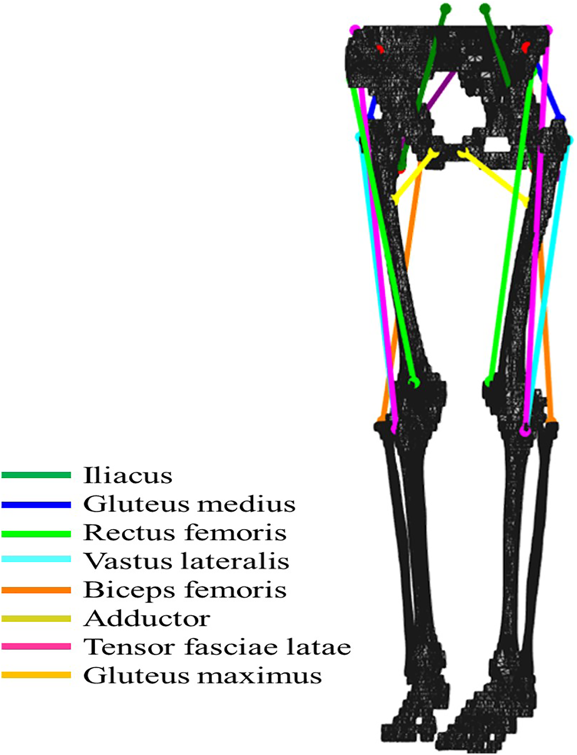
Musculoskeletal model for gait analysis. Both origin and insertion of the eight modeled muscles on the pelvis and femur FE models were decided by referring to their anatomical map.
Inverse dynamics-based optimization method
An inverse dynamic analysis using the musculoskeletal model to calculate values of inter-segmental and muscular forces active during walking was performed. The input data of joint angles and ground reaction force were obtained from published data. 11,12 The calculated forces had the following characteristics: (I) all joint moments from the inverse dynamics analysis were reproducible (equality constraint) and (II) the sum of the squared muscle stresses was minimized (optimization method). 13,14 All muscles were modeled as ideal force generators, with no contractile or elastic properties, which were based on previous studies. 15
FE analysis
After performing the inverse dynamics analysis, the FE model of the proximal femur was constructed.
FE modeling
A patient-specific FE model of the hip joint and proximal femur was constructed from CT images taken from a healthy 83-year-old female volunteer (cortical and cancellous bone maps of the femur). CT images were taken at 0.625 mm intervals and were obtained in the supine position using a Phillips MX 8000 (Phillips Medical Systems) spiral CT scanner and an axial scanning protocol (140 kVp, Auto mA, Noise Index 13). For model production, all data were converted to Digital Imaging and Communications in Medicine files. The 3-D geometric models were reconstructed using 3-D Slicer ver. 3.41.0 (The Brigham and Women's Hospital and Massachusetts Institute of Technology, MA, USA) and SolidWorks 2013 (Dassault Systems SolidWorks Corp, MA, USA). The 3-D geometric models consisted of the pelvis, the surrounding cartilage, the proximal femur, and implants (if necessary).
In this study, three models of the hip joint were prepared: (I) healthy hip joint without fracture; (II) osteosynthesized femoral neck fracture using two Hansson pin® (HP, Selzach, Switzerland) or hooked pins (widely used in Japan and other Scandinavian countries); and (III) osteosynthesized femoral neck fracture using Dual SC Screw (DSCS®, KiSCO, Kobe, Japan) or sliding screw with a plate sustaining angular stability (Figure 2). In models (II) and (III), the fractures were unstable with a 70° vertically oriented fracture line, consistent with a Type III Pauwels fracture. Undescribed data of detailed structures of the aforementioned implants were measured manually to reproduce implant. The 3-D geometric models were subsequently imported into ANSYS version 14.0 (ANSYS Inc., Canonsburg, PA, USA), a meshing tool for FE analysis, and meshed into four-node tetrahedral (C3D4) elements. The models were discretized to approximately 70,000 elements with 20,000 nodes (Table 1).
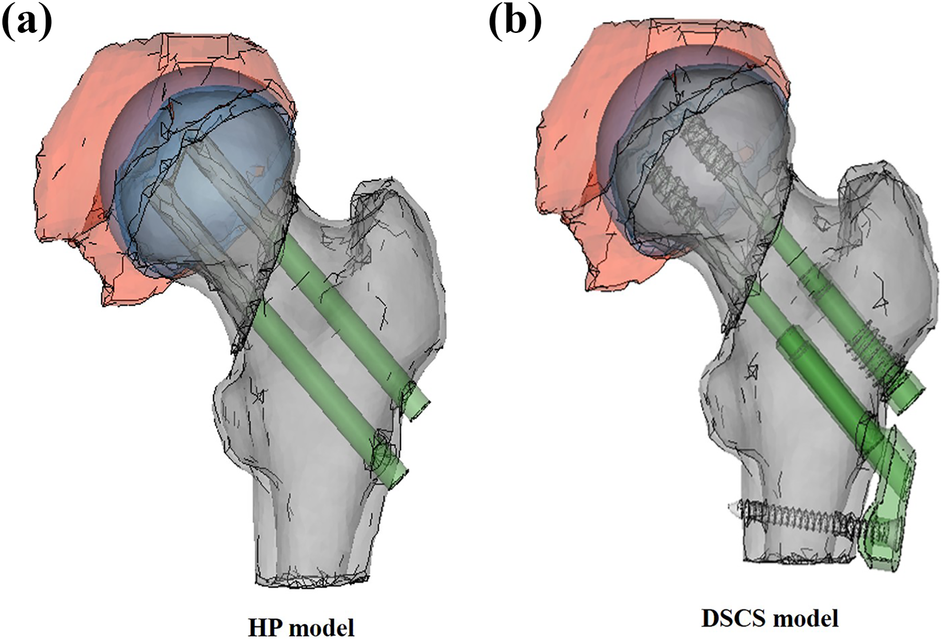
3-D solid fracture models with implants for fixation: (a) HP-treated model and (b) DSCS-treated model.
Elements and nodes of hip joint construct, not including implants.a
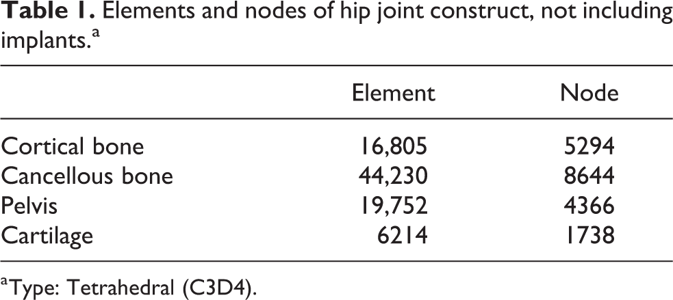
a Type: Tetrahedral (C3D4).
The mechanical properties (Young’s modulus and Poisson’s ratio) were obtained from the literature 16,17 (Table 2). Young’s moduli for cortical bone, cancellous bone, and the implant were set at 13.3, 0.15–0.44, and 110 GPa, respectively. Moduli for cancellous bone varied in accordance with the location on the femur, namely the head, neck, or shaft. Poisson’s ratio was assigned as 0.3 for both cortical and cancellous bone. The coefficient of friction was 0.1 for implant–bone pairing. 18 All materials were assumed to be homogeneous, isotropic, and linear elastic.
Material properties of finite element models.

Loading and boundary conditions
Hip contact forces to the hemispherical surface of the femoral head and four muscle forces, gluteus maximus, gluteus medius, adductor, and tensor fasciae latae, were loaded. 19 Each muscle was delineated in a straight line. The boundary data in one gait cycle for our dynamic FE analysis were extracted from the inverse dynamics starting from the neutral position (0° flexion) of the non-weight bearing phase (swing phase) of the gait cycle. The direction and magnitude of the loads varied without interruption in accordance with the walking cycle (Figure 3). Direction of the muscles continued to change from posterior to anterior during the heel touch and toe-off phase of walking, depending on hip joint movement. Regarding the magnitude, hip contact force in our model had double peaks at the early and late stance phase that coincided with a previous report evaluating surface force of a walking patient who had femoral head arthroplasty, with a sensor on the top of prosthesis. 20 During the non-weight bearing phase, only minimal strains were observed, reflecting no reactant force from the floor surface. Both gluteus maximus and medius muscles reached peak loading during the first half of stance phase and decreased at the late stance phase. 21 The loading of the adductor muscle was highest during the middle stage of the stance phase and showed a second highest peak at the end of the stance phase or toe off. Loadings were found continuously variable from in-house musculoskeletal model using an inverse dynamics analysis.
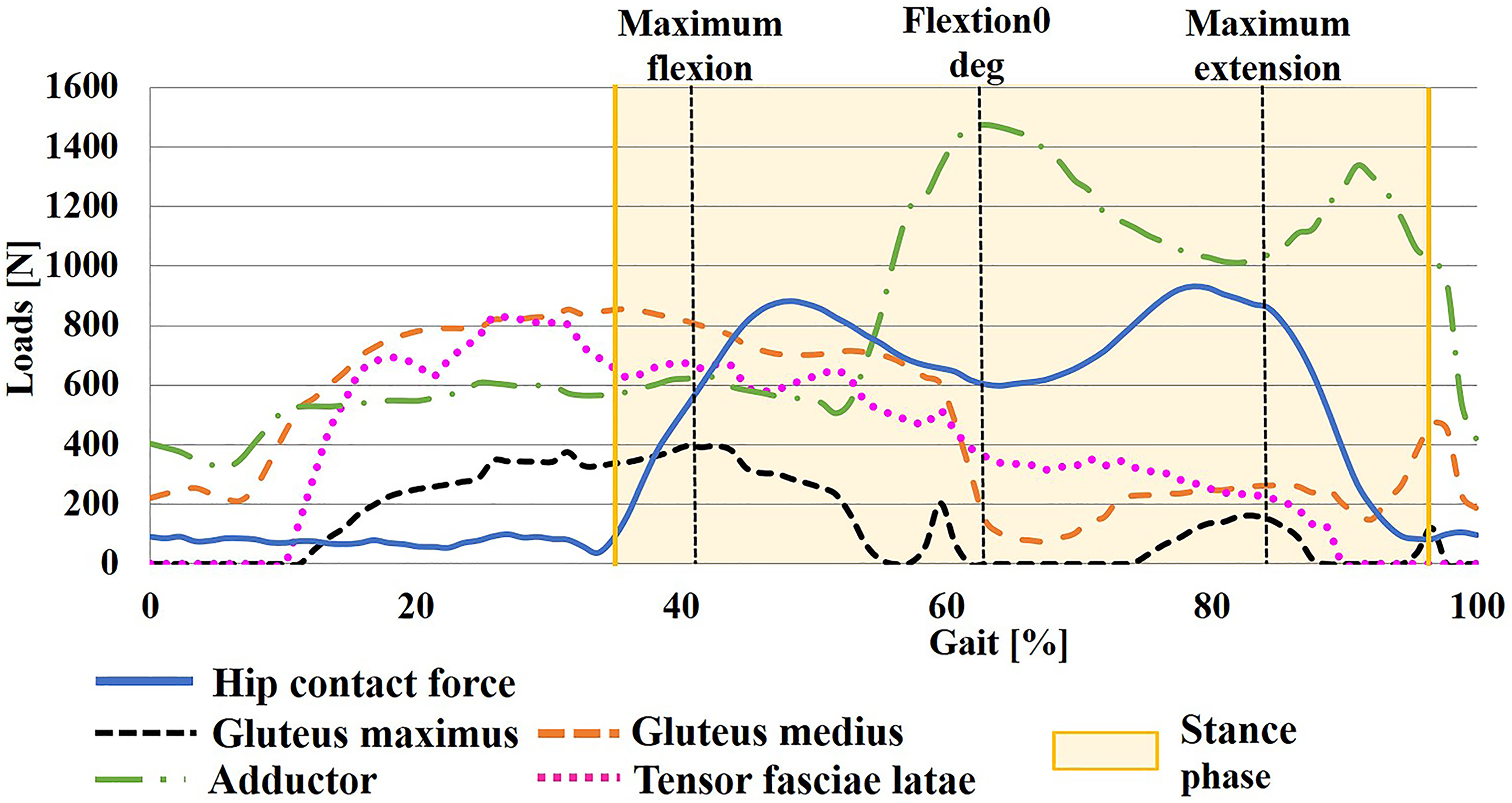
Time history curve of loadings. Resultant hip contact stress and muscles are adjusted through optimization to minimize a cost function during walking, note all muscular strength changing during walking cycle.
Boundary conditions were applied after loading. The motion was given as displacement constraints in the distal end of the femur model, allowing sagittal swinging motion to simulate physiological walking, ranging from flexion of 23° and extension of 15° at the hip joint. Since muscle forces were set not to influence on dynamic behavior, femoral movement follows the designated spacious position. Besides, no external boundary conditions were applied to the femoral head to prevent dislocation at the hip joint.
Anatomical spots for stress analysis
Time-varying stress distribution during walking was evaluated using a dynamic explicit method via ABAQUS (ver.6.14-5 Dassault Systèmes Simulia Corp., Providence, RI, USA). The time-varying von Mises stresses at two representative spots located on the medial cortex at femoral neck fracture site and the lateral pin (presumed) insertion holes to anticipate potential subtrochanteric fracture were evaluated since major postoperative implant-related complications occur in these regions. 6,7 To standardize all the given conditions, the same changing magnitude and direction of loading were applied to the three models (one healthy and two osteosynthesized), supposing that all models walk in a similar manner.
Verification of FE results
Previous studies validate the FE models used in this study and point to their reliability. Qian et al. 22 showed that stress on the medial femoral neck cortex in an intact model in the early, mid, and late stance phase was 18.1, 10.5, and 12.1, respectively, that was almost coincided with our data of about 18, 11, and 12, respectively. Fox et al. 23 calculated maximum stress at lateral subtrochanteric cortex during the walking cycle in an intact bone and femoral fracture model with intramedullary nail. Maximum stress value during walking cycle around the proximal screw among intact bone and nailed models was about 41 and 106, respectively, while seemingly corresponding to our results of 17 and 110, respectively. In addition, the results of Geraldes et al. 24 were in coherence with our results. They created a complete 3-D model of a femur using a mechanical loading environment and evaluated the medial femoral cortex and lateral subtrochanteric zone simulated walking conditions in healthy individuals. These studies demonstrate that stress values in our current study are within the acceptable range of reliability.
Ethical approval and consent
This study was approved by the Ethical Review Board of the Konan Hospital. All patients were provided with a written informed consent.
Results
Time-dependent stress value of FE analysis
In our analysis, the values of stress showed variance in each phase of walking under different values of loading and varied direction of muscular forces, since this model reflects dynamic motion. This study showed the predicted von Mises stress at two designated spots on the proximal femur (medial femoral cortex coinciding with the fracture line and lateral subtrochanteric cortex presuming distal pin insertion) in each of the three models.
At the medial femoral neck cortex of the fracture line, the intact model showed a consistent value throughout the walking cycle. Both HP model and DSCS model were highest at approximately 30 MPa, contrasting the former in the late phase of stance with the latter in the early phase (Figure 4). At the lateral subtrochanteric cortex, the intact model had the lowest score in the stance phase, due mainly to the absence of a drilling hole. The HP model demonstrated a substantially elevated value throughout the stance phase and was highest at the late phase of stance, exceeding well over half value of cortical yield stress. 25 The DSCS model had moderately elevated values during the weight-bearing phase and was highest prior to the stance phase. Highest values at the lateral subtrochanteric cortex were 18.8, 104.0, and 63.1 MPa in the following intact, HP, and DSCS models, respectively (Figure 5).

Predicted von Mises stress distribution on medial femoral neck cortex, revealing small changes in three models.

Predicted time-dependent changing von Mises stress distribution on lateral subtrochanteric cortex. Note that the values on HP were significantly elevated, almost close to yielding stress that may trigger subtrochanteric fractures.
Discussion
Our results demonstrated a time-dependent change in values of stress in both regions evaluated. Majority of previous FE analysis studies at the proximal femur under static conditions presented only one value at each location. 26,27 We believe that neither a single value nor joint angle is representative of the whole outcome of analysis.
In this biomechanical study, DSCS provides a better construct than the HP system in several aspects. In the HP model, a significant increase in stress was observed around the lateral insertion holes. These results may indicate that the femoral head constructed with HP transfers stress to the lateral cortical bone, thus accumulating stress at the lateral cortical edge (Figure 6). The highest value at the lateral cortex marked near yielding stress of cortical bone. On the contrary, the values for DSCS treatment at the lateral cortex declined moderately compared to the HP construct. The proximal femoral body with DSCS tends to sustain hip contact stress as one piece, well distributing the applied stress. HP treatment has been proven to induce more stress concentration through walking compared with DSCS treatment. However, further studies with repeated stress accumulation are necessary to fully understand the vulnerability of HP treatment to lateral subtrochanteric fracture, as stress value still remains within a threshold of breakage.

Presumed mechanism of stress transfer on HP patient: applied stress on hip contact force (a big yellow arrow) travelling along the implants (showing stress transfer in small yellow arrows) to lateral pin holes that have possible risk of subtrochanteric fracture.
This current study set up two variable conditions of muscular force and special joint position during gait motion, in contrast to the conventional model where both are constant as in one leg standing. Regarding muscular forces, several articles using superficial electromyography (EMG) demonstrated variable muscular activation in each muscle during walking. Gluteus muscle EMG activity during walking showed elevation of muscular activity in the initial half of the stance phase. 21,28 Although these clinical results using EMG are not uniform in each patient, their data can be equal in the viewpoint that all the muscular activities change during the walking cycle. As for joint position, Lerner et al. 29 also showed not only variable magnitude of muscular activity during walking, but also joint kinematics while placing reflective markers over anatomical landmarks collected using a 10-camera motion capture system. These studies revealed a changing hip joint angle during walking. Orthopedic surgeons may take these two factors for granted. Our dynamic FE models adapted these variable factors.
There are a few articles that argue that dynamic models have some advantages over quasi-static or static formulation in predicting stress and strain. Lerner et al. 29 simulated backward fall on the buttock with a 3-D FE model of human pelvis–femur–soft tissue complex. Kim et al. 30 introduced an FE model of two anterior cruciate ligament bundles with a tension of 20 N under different angles, using a quasi-static load. Qian et al. 9 stressed that prediction accuracy of peak pressure improved to 33% in dynamic analysis of the FE foot model. However, their construct was a 2D model. Edwards et al. 31 concluded that the largest difference in femoral strains between dynamic simulation and static methods was observed during the first half of stance, and that it was recommended that dynamic simulation in strain magnitude is critical during fracture risk assessment. However, all these studies were recognized within the framework of static evaluation under quasi-dynamic or connecting each value on different static motion angle without velocity, acceleration, and inertia taken into consideration. The importance of the dynamic effect may have been blinded by substituting only the maximum forces during normal walking activity. 28,32 To our limited knowledge, our current study may be the sole model simulating walking, conducting FE analysis under dynamic conditions.
Strong point of our research
First, the models allow for dynamic motion between the femoral head and the acetabulum. It also includes inert phase and acceleration so as to improve the quality of reproducing real walking. Second, we additionally changed the direction as well as the values of muscle force in accordance with variable joint motion. Third, the femoral head was not constrained against the acetabulum to prevent hip dislocation, therefore causing less risk for unusual stress around the femoral head. 33 Fourth, the usefulness of the dynamic models may be extended beyond the framework of fracture analysis to include other fields of research such as in hip arthroplasty.
Limitation
There are several limitations to our study. First, the major limitation is that some of our data were based on different studies, including published articles for subject-specific motion data, and aged female FE model. Our FE model referred to different origin of medium that may not reproduce the similar condition of real walking motion. The use of patient-specific model geometries is mandatory for a thorough clarification of the clinical setting. 27,34 Therefore, we are currently preparing a patient-specific data using motion capture system and a force plate to achieve consistency of data sources. Second, only four muscle forces were set to the FE model, although we selected them as most influential for hip kinematics. 19 Furthermore, application of the remaining muscle forces could affect implementation of a more realistic load. Third, the validation of the loading condition, especially muscle force, could not be completely confirmed, although muscle forces were obtained from mathematical calculation and coincided with superficial EMG data of real gait motion. There are several patterns of muscular magnitude that are changing, hence, it may be difficult to generalize. Fourth, a particular limitation of our bone model is that the actual macroscopic property of cancellous bone, which is orthotropic, was not taken into account (i.e. isotropic and heterogeneous properties were assumed for both cortical and cancellous bone). This drawback seems unavoidable to some extent, considering the current technical standard. In the future, dynamic analysis may be able to investigate the effect of rate-dependent loading and multiple cycle analyses after conquering these limitations. 32
Clinical relevance
The biomechanical results in this study were compared with other published clinical outcomes. Strömqvist et al. 35 argued that 56 of 300 cases (19%) of HP treatment developed radiographic healing complications, that is, re-displacement, nonunion, or segmental femoral head collapse. Weinrobe et al. 36 reported that 26 patients with a fracture angle of 41° or more, fixed with three screws, resulted in 15 successful healing, 9 re-displacement, and 2 reoperations. Of the 53 Garden’s Classification Stage I and II fractures treated with the DSCS system, all showed union except one case. 37 Although explicit comparative studies between these implants with Pauwels type III were not found, our results concurred with those of previous articles.
Conclusion
This current dynamic analysis simulating real walking conditions revealed a time-dependent stress distribution, which is close to daily activities. The authors’ preliminary dynamic analysis is an effective method for assessing postoperative risk of implant-related complications and is the first important step leading to further studies.
We advocate the use of an angular stable apparatus for treating vertical fractures to reduce the risk of postoperative complications.
Footnotes
Declaration of conflicting interests
The author(s) declared no potential conflicts of interest with respect to the research, authorship, and/or publication of this article.
Funding
The author(s) received no financial support for the research, authorship, and/or publication of this article.