
Abstract
Purpose:
This study analysed the accuracy and safety of the fluoroscopic guided percutaneous screws in the upper thoracic vertebrae (T1–T6).
Methods:
Computed tomography scans from 74 patients were retrospectively evaluated between January 2008 and December 2012. Pedicle perforations were classified by two types of grading systems. For medial, lateral, superior and inferior perforations: grade 0 – no violation; grade 1 – <2 mm; grade 2 – 2–4 mm and grade 3 – >4 mm. For anterior perforations: grade 0 – no violation; grade 1 – <4 mm; grade 2 – 4–6 mm and grade 3 – >6 mm.
Results:
There were 35 (47.3%) male and 39 (52.7%) female patients with a total 260 thoracic pedicle screws (T1–T6) analysed. There were 32 screw perforations which account to a perforation rate of 12.3% (11.2% grade 1, 0.7% grade 2 and 0.4% grade 3). None led to pedicle screw-related complications. The perforation rate was highest at T1 (33.3%, all grade 1 perforations), followed by T6 (14.5%) and T4 (14.0%).
Conclusion:
Fluoroscopic guided percutaneous pedicle screws of the upper thoracic spine (T1–T6) are technically more demanding and carry potential risks of serious complications. Extra precautions need to be taken when fluoroscopic guided percutaneous pedicle screws are placed at T1 and T2 levels, due to high medial pedicular angulation and obstruction of lateral fluoroscopic images by the shoulder girdle and at T4–T6 levels, due to smaller pedicular width.
Keywords
Introduction
Pedicle screw fixation in the spine was first introduced by Roy-Camille et al. 1 Comparing to the older methods of fixation using wires and hooks, pedicle screw fixation has superior biomechanical and clinical results. 2 –4 However, the conventional technique of the open pedicle screw placement technique over the upper thoracic spine requires extensive paravertebral muscle dissection to the lower cervical region to expose and identify anatomical bony landmarks for upper thoracic pedicle screw entry point. With the percutaneous fluoroscopic-guided technique, muscle dissection is minimized and no stripping from its bony attachment is required, thus leading to better muscular function, less blood loss, shorter operative time, reduced post-operative pain and thus results in a faster recovery. 5 –8
The T1 and T2 vertebrae have a larger degree of medial angulation among the thoracic vertebras in the axial plane 9,10 and it may be difficult to obtain adequate lateral fluoroscopic due to the obstruction by the patient’s shoulder girdle. The T4–T6 vertebrae have the narrowest pedicle width with a higher risk of medial and lateral pedicle perforation when screws are placed inaccurately. 11 –16 Due to these factors, pedicle screws placement in the upper thoracic vertebrae (T1–T6) are theoretically subjected to a higher risk of misplacement and pedicle breaches which may lead to potentially serious neurological, major vascular and visceral injuries.
In the literature, the perforation rates of percutaneous pedicle screws in the thoracic and lumbosacral spine ranged from 0.4% to 23%. 17 –24 Only one study by Schaefer et al. 25 had reported on the safety of upper thoracic percutaneous screw placement with 72 cervico-thoracic screws in 15 patients (52 cervical screws and 20 upper thoracic T1–T4 screws). Due to the large variability of perforation rates and the lack of studies that specifically looked into the safety profile of percutaneous screws in the upper thoracic region, we conducted this clinical study to analyse the accuracy and safety of fluoroscopic guided percutaneous screws in the upper thoracic vertebrae from T1 to T6.
Methods
Study design
This was a retrospective computed tomography (CT) scan evaluation study of 260 thoracic pedicle screws inserted from T1 to T6 vertebrae in 74 patients. All the subjects were recruited from two centres: (1) University Medical Center Hamburg-Eppendorf, Hamburg, Germany. (2) University of Malaya Medical Centre, Kuala Lumpur, Malaysia. The study duration was between January 2008 and December 2012.
Technique of fluoroscopic percutaneous pedicle screw insertion
This procedure can only be performed if good visualization of the pedicle is obtained on fluoroscopic images intra-operatively. The usage of four-post frame on a Jackson table may ease the manoeuvrability of the fluoroscope. Positioning in a radiolucent Mayfield skull clamp with shoulders taped caudally may allow better visualization of the uppermost thoracic vertebrae. Contraindications for this procedure were obese patients, sclerotic pedicles and poorly visualized pedicle in patients with metastatic spinal disease with extensive pedicle lysis.
A true anterior–posterior (AP) view of the corresponding vertebra was initially obtained (Figure 1). A skin incision of 1.5 cm was made. At T1 and T2, skin incisions were placed 10–30 mm lateral to the lateral border of the pedicle due to the medial angulation of the T1 and T2 pedicles and the thickness of the soft tissue around this region. For T3–T6 vertebrae levels, skin incisions were centred at the lateral border of the pedicle margin. The trocar was inserted and positioned in contact with the bone with the intra-operative imaging showing that the trocar is positioned at the lateral border of the pedicle (right: 2 o’clock, left: 10 o’clock). These starting points are chosen because the conventional starting points (right: 3 o’clock, left: 9 o’clock) are located at the slope of the transverse processes which will cause the trocar to slide medially. Therefore, a starting point above the transverse processes (right: 2 o’clock, left: 10 o’clock) was chosen (Figure 1(a1), (b1) and (c1)). The trocar was then advanced medially. When the tip of the trocar approached the medial border of the pedicle on AP view (Figure 1(a2)), a lateral view was obtained. The trocar on lateral view should be at or slightly deeper than the posterior vertebral margin (Figure 1(b2)). The trocar was advanced until the middle of the vertebral body before a guide wire was inserted (Figure 1(a3), (b3) and (c3)). The length was measured and the screw was then inserted with caution not to allow the guide wire to advance with the screw. The screw size and length was determined based on pre-operative radiographs or CT scan assessment and intra-operative image intensifier estimation.
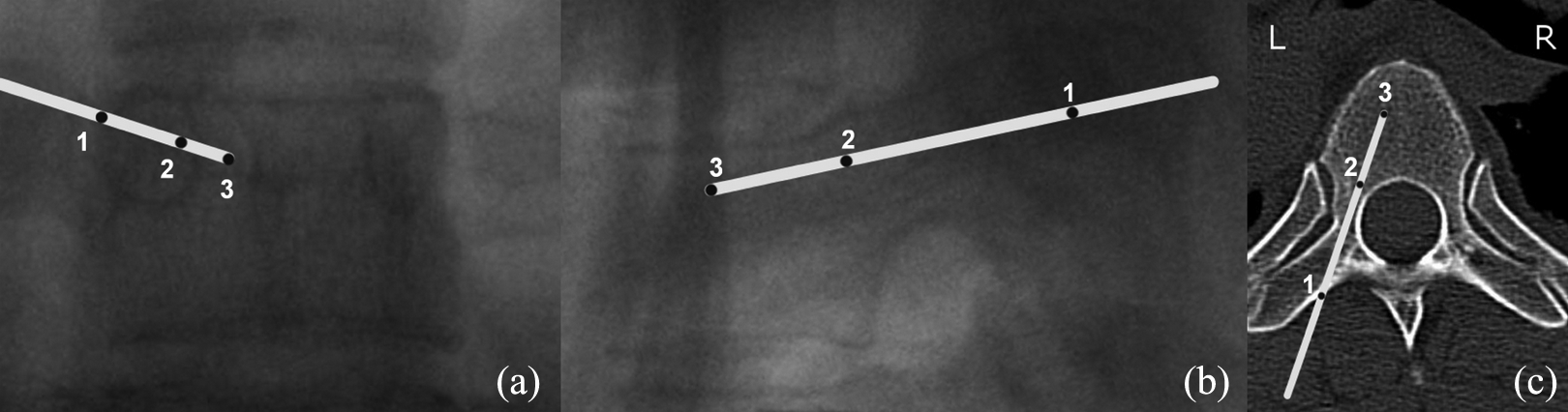
Stages of trocar positions in T6 vertebra: (a) AP image, (b) lateral image and (c) axial CT views; (1) starting point, (2) when tip reached medial border of the pedicle, and (3) final position. AP: anterior–posterior; CT: computed tomography.
Extra-pedicular screws were inserted for small pedicles (<3 mm in diameter), which is usually found at the level of T4–T6 vertebrae. The starting point was similar (right: 2 o’clock, left: 10 o’clock; Figure 2(a1), (b1) and (c1)). The trocar was then advanced along the lateral wall of the pedicle approximately 15–20 mm before a lateral view was obtained (Figure 2(a2i)). The trocar on lateral view should be at or slightly deeper than the posterior vertebral margin (Figure 2(b2i)). The trocar was advanced medially until the middle of the vertebral body before a guide wire was inserted (Figure 2(a2ii), (b2ii) and (c2ii)) and screw inserted.

Trocar positions for extra-pedicular screws insertion in T6 vertebra: (a) AP image, (b) lateral image and (c) axial CT views; (1) initial superficial trocar position, (2i) after trocar advanced along the lateral wall of the pedicle approximately 1.5–2.0 cm, and (2ii) final position. AP: anterior–posterior; CT: computed tomography.
For T1 and T2 levels, to ensure good visibility on the fluoroscope, patients were placed on a Mayfield skull clamp with both shoulders strapped downwards. Alternatively, a method using ‘oblique fluoroscopic images’ to insert percutaneous screws was used (Figure 3). An oblique image parallel to the pedicle was obtained (Figure 3(a)). The amount of rotation of the fluoroscopic arm on the oblique views can be determined from pre-operative CT images. Oblique view parallel to the pedicle axis can be confirmed from the intra-operative fluoroscopic images by positioning the fluoroscopic C-arm to obtain images with the outline of the pedicle touching the lateral margin of the body. The pedicle would appear the largest at this view. Skin incision can be made directly over pedicle, using the fluoroscopic image as an aid. Trocar was placed along the trajectory of the pedicle to touch the bony cortex. Once the trocar touches the bony cortex, the trocar will be inserted directly along the pedicle trajectory for about 15 mm in depth into the bone (Figure 3(b)) before AP image was obtained to check the position of the trocar (Figure 3(c)) and the opposite oblique image (perpendicular to the trocar) was obtained to check the depth of the trocar (Figure 3(d)). Once trocar position was confirmed, the trocar will be advanced to approximately 25–30 mm in depth into the bone and a guide wire was inserted (Figure 3(e)–(g)). Finally, screws were inserted with the guide of oblique, AP and lateral (if visible) fluoroscopic images (Figure 3(h) and (i)).

Alternative technique of inserting T1 or T2 percutaneous pedicle screw: (a) fluoroscope left oblique positioning, (b) trocar insertion, (c) AP checking, (d) fluoroscope right oblique positioning, (e) guide wire insertion, (f) AP checking after two wires inserted, (g) AP checking after T1 and T2 wires inserted, (h) and (i) final screw positions on AP and lateral views. (Figurative diagram on the right illustrates the position of the fluoroscopic C-arm.) R = Right, L = Left. AP: anterior–posterior.
CT examination
Assessment of screw perforation was performed on Picture Archiving and Communication System (PACS) system (Centricity PACS, version 5.0, GE Healthcare, Chicago, Illinois, United States). The protocols for CT imaging of the screws were similar in both centres using 3-mm-thin slice CT images. Axial, sagittal and coronal scans were performed. Evaluation was done by two assessors (CKC and MKK).
Pedicle perforations were classified by two types of grading systems. For medial, lateral, superior and inferior perforations, the pedicle perforations were assessed using a classification initially described by Gertzbein 26 with modification by Rao et al. 27 (grade 0: no violation; grade 1: <2 mm perforation; grade 2: 2–4 mm perforation and grade 3: >4 mm perforation). For anterior perforations, the pedicle perforations were assessed using a modified grading system (grade 0: no violation; grade 1: <4 mm perforation; grade 2: 4–6 mm perforation and grade 3: >6 mm perforation). Grade 2 perforations were considered perforations with possible complications. Grade 3 perforations were considered ‘critical perforation’ with high risk of early or late complications.
Data collection
Data collected by the assessors was immediately entered into a computerized spread sheet for comparison and analysis. Perforation rate was defined as the total number of perforations divided by the total number of screws inserted multiplied by 100%. Clinical complications related to percutaneous screws breach or perforations were documented as well as any remedial actions taken when it occurs. Analyses were done with SPSS v.14 statistical software (SPSS, Chicago, IL, USA). Inter-rater reliability was assessed using Cohen’s κ statistics.
Results
CT scans from 74 patients (260 pedicle screws) who had undergone surgery using fluoroscopic guided percutaneous pedicle screws were evaluated. The inter-rater reliability between the two evaluators was adequate with a kappa value of 0.79. The mean age was 58.6 ± 13.6 years. There were 35 (47.3%) male patients and 39 (52.7%) female patients. The main aetiology was tumour (75.7%). Other aetiologies were infection (20.3%) and trauma (4.0%; Table 1).
Patient demographics based on age, gender and aetiology.

Values are mean ± SD.
A total of 260 screws were inserted. There were 32 screw perforations which accounts to a perforation rate of 12.3%. There were 29 grade 1 perforations, 2 grade 2 perforations and 1 grade 3 perforations which accounts to perforation rates of 11.2%, 0.7% and 0.4%, respectively (Table 2). None of the perforations led to pedicle screw-related complications. The distribution of percutaneous pedicle screws, perforations and perforation rates according to vertebral levels, direction of perforations and grade of perforations is illustrated in Table 3. The perforation was highest at T1 (33.3%) followed by T6 (14.5%) and T4 (14.0%). Majority of the perforations were medial (40.6%) followed by anterior (34.4%), lateral (21.9%) and superior (3.1%). There were no inferior perforations documented. We noted that there were two peaks in perforations, first peak is over the T1 level and second peak is between T4 and T6 vertebrae levels (Figure 4). Grade 2 perforations occur over the right T6 (medial perforation) and right T4 (anterior perforation). Grade 3 perforation occurred at left T4 with an anterior perforation (Figure 5).
Total number of percutaneous pedicle screws, screws with perforations and the perforation rate.

The distribution of percutaneous pedicle screws, perforations and perforation rates according to vertebral levels, direction of perforations and grade of perforations.

G1: grade 1; G2: grade 2; G3: grade 3.
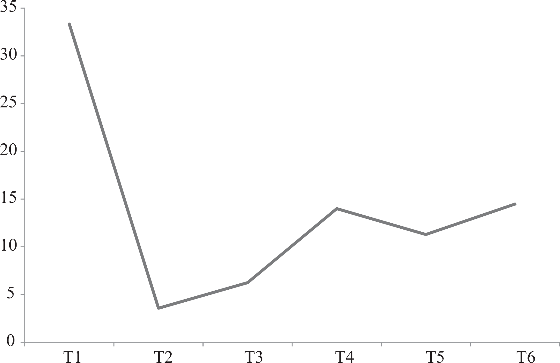
Perforation rates distribution in the upper thoracic region.

Grade 3 left anterior perforation (arrow).
When comparing between Europeans and Asians from the two centres, there were no significant differences noted in gender, aetiology, total screws, total perforations and grade 1 perforations. There were no grade 2 or 3 perforations among the Europeans. The only difference noted between both groups was the mean age, in which Europeans were significantly older than Asians.
Discussions
In the literature, the percutaneous pedicle screw fixation had been reported to have perforation rates between 0.4% and 23% in the thoracic and lumbosacral spine. 17 –21,23,24,28 However, none of these articles directly evaluate the safety of this technique in the upper thoracic spine (T1–T6) except Schaefer et al. 25 who reported the accuracy of 72 cervico-thoracic screws in 15 patients (52 cervical screws and 20 upper thoracic T1–T4 screws). They found that there were no perforations for the upper thoracic screws. However, the numbers of thoracic screws analysed were few and this study combined an open occipito-cervical–thoracic system with a trocar system to insert screws percutaneously through a mini open approach.
The usage of CT guided computer-assisted or navigation percutaneous pedicle screw placement is an alternative to solely fluoroscopic guided percutaneous pedicle screw placement. There were several authors who had reported its perforation rates ranging from 3.0% to 7.3%. 29,30 Despite its advantages of less radiation to operative personnel, the fluoroscopic guided screws placement would still remained as the main practical technique in many centres (especially in the developing countries) due to the cost and availability of these computer-assisted devices.
In this study, we specifically analysed the safety and accuracy of fluoroscopic guided percutaneous screws insertion in the upper thoracic spine (T1–T6). The placement of percutaneous pedicle screws in T1 can be challenging as T1 pedicle is the most medially angulated pedicle in the thoracic spine. An et al. 9,10 had reported that the average medial pedicle angulation at T1 was 31.8° and at T2 was 26.5°. This is compounded by the difficulty to obtain clear lateral fluoroscope images due to the obstruction caused by the shoulder girdle, which is a very crucial fluoroscopic view during the insertion of the percutaneous screw. Bayley et al. 31 had suggested placing the patient in a special prone position with a bolster placed under the sternum allowing the scapula to fall forward avoiding the overlay of the shoulder girdle on the lateral fluoroscopic images. Singh et al. 32 had suggested the usage of oblique fluoroscopic images to identify the anatomical spine levels over the distal cervical and proximal thoracic spine. As described in the ‘Methodology’ section, ‘oblique fluoroscopic images’ were used as an alternative method to insert T1 and T2 percutaneous pedicle screws in the event that the lateral fluoroscopic images were inadequate (Figure 3). In our study, we noted that the highest perforation rate was at T1 vertebra (33%) despite our efforts to ensure adequate fluoroscopic visibility either by placing patients on a Mayfield skull clamp with both shoulders strapped downwards or using an alternative method using ‘oblique fluoroscopic images’ to insert percutaneous screws. Even though all perforations were only grade 1 with no clinical complications, only a total of 12 screws were inserted in T1 and due to the this small number of screws, conclusions made may not be accurate and further studies with larger series of screws may be needed.
For T4–T6 levels, the pedicle width is the narrowest in this region compared to other thoracic vertebras. This exposes them to a higher risk of perforations. 11,12,14,15 Cinotti et al. 11 found that the smallest pedicles (<5 mm) were located in the region between T4 and T8 with the narrowest at T6 (mean 4.3 mm) which may not be suitable for screw insertions in their dissection of 11 cadaveric spines. McLain et al. 12 found that at T4, 61% of pedicles were too small, at T5, 67% were too small and at T6, 75% were too small to accept a 5.5-mm screws from dissection of 18 human cadavers. Others had documented the narrowest pedicle width was located at T4 33 –35 or at T5 15,36 –38 which may subject them to higher risks of perforation. In our study, we found that there was a peak in the perforation rate at T4 (14.0%) and T6 (14.5%). Therefore, to minimize the pedicle perforation at this region, we suggest using ‘extra-pedicular screw insertion technique’ if the pedicle width is <3 mm on pre-operative CT scan assessment (Figure 2).
We found that the total perforation rate of upper thoracic spine (T1–T6) was 12.3% (Table 2) which is comparable to the open method of pedicle screw placements. 36,39 –46 Despite none of the perforations caused screw-related complications in this study, there were a grade 2 medial perforation which may result in neurologic complications and a grade 2 as well as a grade 3 (Figure 3) anterior perforation which may risk injury to mediastinal visceral structures. O’Brien et al. 47 had reported a case of oesophageal injury after instrumentation of the T3 vertebrae due to backward pressure from the endotracheal tube and trachea that pushed the oesophagus unto the tip of the anterior perforated screws. Belmont et al. 39 had reported a higher incidence of anterior perforation from T1 to T4 vertebra compared to T5 to T12 with open pedicle screw placement. Open pedicle screws placement allows palpation and sounding of the anterior vertebral cortex with a blunt probe but this is not possible for percutaneous pedicle screw placement. The depth of percutaneous pedicle screw placement depends on pre-operative screw length estimation on CT scans and intra-operative fluoroscope images. Therefore, determining the length and the depth of percutaneous pedicle screws during surgery remains to be a great challenge in the upper thoracic levels as lateral fluoroscope images may be unclear due to obstruction by the shoulder girdle or the rib cage. We advise placement of shorter screws (from planned pre-operative screw length) when the distance between the oesophagus and the anterior vertebral body is small or when there is uncertainty in the screw depth during surgery.
There were several limitations in this study. This was a retrospective study and patients who had no CT scan post-operatively were excluded. The amount of radiation exposure to patient and operative room personnel was not reported. Peri-operative and intra-operative complications that occurred (e.g. wound infections, urinary tract infections, lung infections and complications, etc.) but not related to screw breach were not included in this study. The number of screws assessed was small especially at T112 and T228 and further studies with larger series of screws may be needed.
Conclusion
Despite the comparable perforation rates to open pedicle screws, fluoroscopic guided percutaneous pedicle screws of the upper thoracic spine (T1–T6) are technically more demanding and carry potential risks of serious complications. Extra precautions need to be taken at T1 and T2 levels, due to high medial pedicular angulation and obstruction of lateral fluoroscopic images by the shoulder girdle and at T4–T6 levels, due to smaller pedicular width.
Footnotes
Declaration of conflicting interests
The author(s) declared no potential conflicts of interest with respect to the research, authorship, and/or publication of this article.
Funding
The author(s) disclosed receipt of the following financial support for the research, authorship, and/or publication of this article: Nils Hansen-Algenstaedt receives financial/material support (royalties, patents, etc.) from Globus Medical, Stryker and SpineArt. He is an active consultant for SpineArt, DepuySynthes and Stryker. He used to be an active consultant for Globus Medical and Vexim.