
Abstract
Objectives:
The primary objective of this study is using an anodizing intermediate layer to improve corrosion resistance and adhesion of hydroxyapatite coated AZ31 alloy for applications in biodegradable implants.
Methods:
An anodizing intermediate layer was formed on the surface of AZ31 substrate at various anodizing voltage of 10, 20, 30, and 40 V respectively by anodizing process. HAp was grow on the surface of AZ31 substrate at 90°C and pH solution of 7.5 by chemical solution treatment method for 2 h. The coated samples were evaluated their corrosion behavior by Electrochemical measurements and biodegradation behavior by immersion test in Hank’s balanced salts solution (HBSS) for 28 days via amount of Mg2+ ion released. While, their adhesion strength were evaluated by pull-off method. The amount of Mg2+ ions released of the samples was quantified by the Inductively coupled plasma mass spectrometry.
Results:
An anodizing intermediate layer was successfully synthesized at various voltages by anodizing process and HAp coatings were prepared by chemical solution treatment method. The corrosion rate of hydroxyapatite coated AZ31 alloy with an anodizing intermediate layer decreased 4.4 times, while adhesion strength increased about two times compared to the HAp coated AZ31 specimen without an anodizing layer and achieved ~14.70, ~6.92 MPa, respectively. After immersion test in HBSS, the adhesion strength of HAp/AZ31-HBSS-specimen decrease to 45% because of large corroded areas with depth holes of hundreds of micrometers. The slighter decrease in adhesion strength of HAp/30V/AZ31-HBSS-specimen to 22% is due to the contribution of the anodizing intermediate layer.
Conclusion:
HAp coated AZ31 alloy specimen with the existence of a porous structure with an elliptical shape, uniform and high density of MgO on the surface at anodizing voltage of 30 V resulted in a significant increase in corrosion resistance and the adhesion strength of HAp coatings.
Introduction
Magnesium and its alloys are of great interest for biomedical applications.1–3 Most studies have considered magnesium materials in the implant process due to their excellent mechanical properties and lifetime.4,5 They prove to be suitable for applications in blood vessel intervention and orthopedics, thanks to their elastic modulus closely matching that of bone.2,6–8 It is noteworthy that the Mg2+ ion, as the fourth most abundant cation in the human body, is essential for physiological functions and metabolic processes, with daily consumption recommended at 250–500 mg per day. 9 The biodegradability is considered as the biggest advantage of Mg alloys compared to other metallic biomaterials because they have the ability to degrade inside the human body to avoid the secondary surgery. 8 Additionally, magnesium exhibits excellent properties, including low density, a high strength-to-weight ratio, remarkable dimensional durability, effective electromagnetic shielding, superior damping capacity, and high machinability.10,11 However, the rapid corrosion of magnesium and its alloys within the human body can result in a loss of mechanical integrity, hindering substantial bone rebuilding before deterioration.9,12,13 The primary challenge in utilizing Mg as a biodegradable implant material lies in its uncontrollable corrosion or degradation rate and poor antibacterial properties. To enhance the corrosion resistance of Mg and its alloys, various surface treatment methods, such as conversion coating, plating, vapor deposition, anodization, polymer coatings, arc-discharge plasma, and gas-flame spray, have been investigated.10,12,14–19 Among the available techniques, the anodizing process is favored for its high efficiency and environmental friendliness. It proves to be a useful method in controlling the degradation rate of magnesium alloys as it can modify the composition and structure of an anodizing film, contingent on the electrolyte composition and anodizing voltage.2,12,14,20–22 The anodizing process is driven by a high-field mechanism achieved through the superimposition of a high electric field.23–25 This enables a solid-state migration process of the oxidized metallic cations from the substrates and the anions from the electrolyte, specifically O2− in an aqueous solution derived through water deprotonation. 25 Additionally, other anions can be introduced in lower concentrations than oxygen ions in an aqueous solution. Extensive research on the anodizing process has revealed that the resulting anodizing layers typically exhibit a thickness ranging from 5 to 30 µm, featuring high hardness, density, electrical resistance, and wear resistance. Moreover, the size and arrangement of pores in the anodizing layer are influenced by various factors such as electrolyte characteristics, temperature, anodizing current density, and voltage. Generally, a lower voltage produces a finer porous structure, while the pore dimension increases with treatment time and voltage. Therefore, a large number of micro-pores or high porosity is the main drawback of the anodizing layers for long-term surface protection. Thus, it is still necessary to tailor the structure and composition of the anodized layer for better anti-corrosion properties.9,26 Hydroxyapatite (HAp; Ca10(PO4)6(OH)2) coatings on metallic implants have been developed for applications in orthopedics and dentistry due to their chemical and biological similarity to human bone tissues, along with their capacity to bond directly to surrounding tissues.8,20,27–33 The recent researchs indicated that HAp coatings on AZ31 and WE43 substrates exhibit a slow degradation rate, making them suitable for temporary implant applications.28,30–32 However, the weak adhesion between the HAp coating layer and the AZ31 substrate may lead to coating detachment during implantation.
Thus, the primary aim of this study is to create an anodizing intermediate layer to enhance the properties of the HAp coating on the AZ31 alloy. The influence of voltage on the formation of anodizing intermediate layers on the AZ31 substrate was investigated; the corrosion resistance, degradation rate, and adhesion strength of HAp coating on AZ31 alloy with and without an anodizing intermediate layer were studied.
Methods
Preparation of substrates, anodizing intermediate layer, and HAp coatings
An extruded AZ31 magnesium (Mg) alloy rod, supplied by Osaka Fuji Industrial Co., Ltd., was employed for the substrates, with its composition specified in Table 1. The alloy rod was then machined into disc specimens with a diameter of 15 mm and a thickness of 2 mm. Subsequently, the specimens were ground and polished in a grinding polishing machine using silicon carbide (SiC) papers with grit sizes ranging from 600 to 1500 and a diamond solution (1 μm). Prior to the anodization process, the specimens were ultrasonically cleaned in an acetone solution for 10 min and dried with hot air.
Chemical composition of AZ31 magnesium alloy (mass %).
The intermediate layer was fabricated by the anodizing process, using the AZ31 alloy as the anode (positive pole) and stainless steel as the cathode (negative pole) in a two-electrode wiring system. The electrolyte’s chemical composition included 1 M NaOH, 0.5 M Na2SiO3, and 0.05 M Na3PO4. Anodization was performed within a voltage range of 10–40 V for 600 s, utilizing a power source (IMS-CPR-02). To maintain optimal temperature, a cooling system was employed, which involved a container filled with cold water surrounding the electrolyte tank. After the process was completed, the samples were dried using a stream of air.
The HAp layer was synthesized using the chemical solution deposition method. The composition of coating solution included 0.5 mol/L ethylenediaminetetraacetic acid calcium disodium salt hydrate (Ca-EDTA: C10H12N2O8Na2Ca), 0.5 mol/L potassium dihydrogen phosphate (KH2PO4), and sodium hydroxide (NaOH). To adjust the pH of the coating solution to 7.5, the NaOH solution was added an equal volume of 0.5 mol/L Ca-EDTA and 0.5 mol/L KH2PO4 mixture. Subsequently, disc specimens were immersed in the treatment solution at 90°C for 2 h. Finally, the specimens were withdrawn from the solution, rinsed with pure water, and dried under ambient conditions for subsequent characterization.
Characterizations
The crystal structures of the HAp coatings and the anodizing layers were characterized by the X-ray diffractometry (XRD; Bruker, D2 Phaser) using Cu-Kα radiation (λ = 1.54184 nm) at a scanning speed of 2° per min. The surface and the cross-sectional morphology of the specimens were observed by field-emission scanning electron microscope (FE-SEM; FEI, Quanta FEG250) equipped with an energy-dispersive X-ray spectrometer (EDS; TEAM EDS, EDAX). After the adhesion test, the surface and cross-sectional topography of the specimens was measured by an optical microscope (VIEWME, BUEHLER).
Electrochemical measurements
A polarization test was carried out by a potentiostat (Autolab PGSTAT-302N, Metrohm/Netherlands) for the anodizing intermediate layers and the HAp coatings with or without an anodizing layer in Hank’s balanced salts solution (HBSS) with its following chemical composition: 8.00 g/L of NaCl; 0.40 g/L of KCl; 0.35 g/L of NaHCO3; 0.048 g/L of Na2HPO4; 0.06 g/L of KH2PO4; 1.00 g/L of D-Glucose and 0.01 g/L of phenol red at 37 ± 1°C. Before the tests, specimens were trimmed to fit into a holder electrode with a surface area of 1 cm2. A three electrodes cell was used in which the counter electrode was made of platinum, the reference electrode was the saturated Ag/AgCl, and the specimen was the working electrode. First, the open circuit potential was measured for 600 s. Subsequently, polarization curves were measured in comparison with the open circuit potential (Eocp) in the potential range from −0.25 V to +1.0 V at a scan rate of 1 mV/s. Besides, electrochemical impedance spectroscopy (EIS) was also used to investigate the corrosion resistance of AZ31 alloy with and without several representative coating layers, which was performed in the frequency range of 10.000–0.1 Hz with 10 points per decade and amplitude of 10 mV at the open circuit potential (Eocp).
Immersion test
HAp coatings were immersed in Hank’s balanced salts solution (HBSS) with the surface area to solution volume ratio of 50 mL: 1 cm2 for 28 days at 37°C under a 5% CO2 atmosphere. The amount of Mg2+ ions dissolved in the solution was quantified at 1, 3, 5, 7, 14, 21, and 28 days by the Inductively coupled plasma mass spectrometry (ICP-MS) with the equipment of Elan 9000 Perkin Elmer, USA. The immersion test was conducted three times for each type of specimen. After 28 days of immersion, all specimens were retrieved from the solution for further characterization.
Adhesion test
The adhesion test was carried out by a pull-off method using PosiTest® AT pull-off adhesion testers (Quick Guide V.5.2). Adhesion strength of the HAp coatings and anodizing intermediate layers was evaluated, and those with the HAp layers after the immersion test was also evaluated to investigate the effect of corrosion. In the adhesion test, a 10 mm diameter Al dolly was glued onto the surface of HAp and the anodizing intermediate layers on AZ31 substrate specimens using an epoxy resin (Epoxy Adhesives Araldite® 2011-A/B). During the curing process of the epoxy resin, a force of 2N was loaded on the Al dolly at room temperature for 48 h. After 48 h, the dolly was pulled up at a crosshead rate of 4.0 MPa/s until it completely detached from the specimen. The adhesion test was conducted three times for each type of specimen.
Results
Figure 1 depicts the XRD patterns of AZ31 alloy coated by anodizing layers at various anodizing voltages in range of 10–40 V and HAp coatings with and without an anodizing intermediate layer. Those specimen are abbreviated as 10, 20, 30, 40 V, HAp/AZ31, and HAp/30V/AZ31, respectively. MgSiO3 (JCPDS No.11-0273), Mg3(PO4)2 (JCPDS. No.33-0876), and MgO (JCPDS No.78-0430) emerge as the principal phases within the anodizing layers (Figure 1(a)). The diffraction peaks of HAp (JCPDS No.09-0432 ) were observed at 26.18°, 31.77°, 48.61°, and 53.85° on the HAp/AZ31 and HAp/30V/AZ31 specimens (Figure 1(b)), validating the presence of HAp coatings on the AZ31 alloy substrate. Notably, the (002) HAp peak at 26.18° exhibits the highest intensity compared to other HAp peaks, consistent with findings from prior studies.28,32,34,35
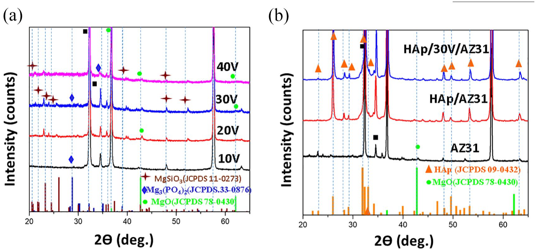
XRD patterns of specimens: (a) anodizing layers at various voltages, (b) HAp coatings with and without an anodizing intermediate layer, and AZ31 substrate.
Figure 2 shows SEM images of the surface morphology of the anodizing layers at various voltage and HAp coatings with and without an anodizing intermediate layer. The anodizing layers indicate the increase in dimension of the porous as the anodizing voltage increases. Specifically, at a lower anodizing voltage (10 and 20 V), a few irregularly shaped pores with small sizes appear on the surface of AZ31 substrates (Figure 2(a) and (b)). As the anodizing voltage rises to 30 V, a porous structure emerges with an elliptical shape, exhibiting a relatively uniform and high pore density of MgO layer (Figure 2(c)). At anodizing voltage of 40 V, the pore sizes continue to expand and deepen within the specimen, resulting in non-uniform porous structures with pore entrances widening to tens of micrometers (Figure 2(d)).
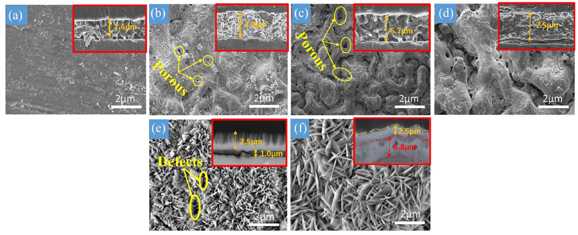
Surface and cross-sectional morphology of the specimens: (a) 10 V, (b) 20 V, (c) 30 V, (d) 40 V, and (e) HAp/AZ31, (f) HAp/30V/AZ31.
Meanwhile, flower-shaped aggregates consisting of rod-shaped crystals of various sizes were observed on the surface of HAp/AZ31 and HAp/30V/AZ31 specimens (Figure 2(e) and (f)). The rod-shaped crystals in the HAp coatings exhibited growth when an anodizing layer was employed. Conversely, the HAp coating without an intermediate layer indicated some defects on the surface. These defects are observed more clearly on cross-sectional SEM images of HAp coated AZ31 alloy specimen without an anodizing intermediate layer which are inserted in Figure 2(e). The thickness of the anodizing layers at 10 V is 2.6 µm. This thickness increases to 4.8, 5.7, and 7.5 µm at anodizing voltages of 20, 30, and 40, respectively. Within the HAp/AZ31 specimen, a relatively dark region is noticeable between the inner dense layer and the AZ31 substrate with a a structure of several micro-cracks. The HAp coatings comes next, displaying a two-layer structure with an outer porous layer containing rod-shaped crystals and an interior solid layer. The HA layer has a total thickness of 3.5 µm, in which, the inner layer demonstrates a dense structure with a thickness of approximately 1 µm and the thickness of rod-shaped layer measures about 2.5 µm. Notably, in the HAp/30V/AZ31 specimen, it is observed that two main layers are separated by a not very clear wavy boundary, consisting of a denser solid inner layer of an anodizing intermediate layer and outer HAp coatings. It is shown on the small figure inserted on the right corner of Figure 2(f).
The composition at various areas on cross-section SEM images of specimens is evaluated by EDS analysis in Figure 3. For the AZ31 substrate treated at an anodizing voltage of 30 V (Figure 3(a)), the composition of the anodizing layer reveals the atomic content of 42.98%.at Mg and 48.75 at.% O (area-1). Moreover, the presence of Si (4.06 at.%) and P (1.02 at.%) in this layer is attributed to the formations of Mg3(PO4)2 and MgSiO3 during the anodizing process. Conversely, the AZ31 substrate exhibits higher Mg content (>80 at.%) with low Al and Zn content. In the HAp/AZ31 and HAp/30V/AZ31 specimens, both coatings contain Ca, P, and O elements (area-3, Figure 3(b) and area-2, Figure 3(c)). The presence of oxygen is attributed to surface oxidation of the AZ31 substrate and the formation process of the HAp coating.30,32 Specifically, the Ca/P ratio of the HAp coating in the HAp/AZ31 specimen directly formed on the substrate surface is 1.36, while it is 1.5 in the HAp/30V/AZ31 specimen. These results indicate that the pure HAp coating deposited directly lacks calcium ions due to the incorporation of an amount of Mg2+ ions into the HAp lattice.
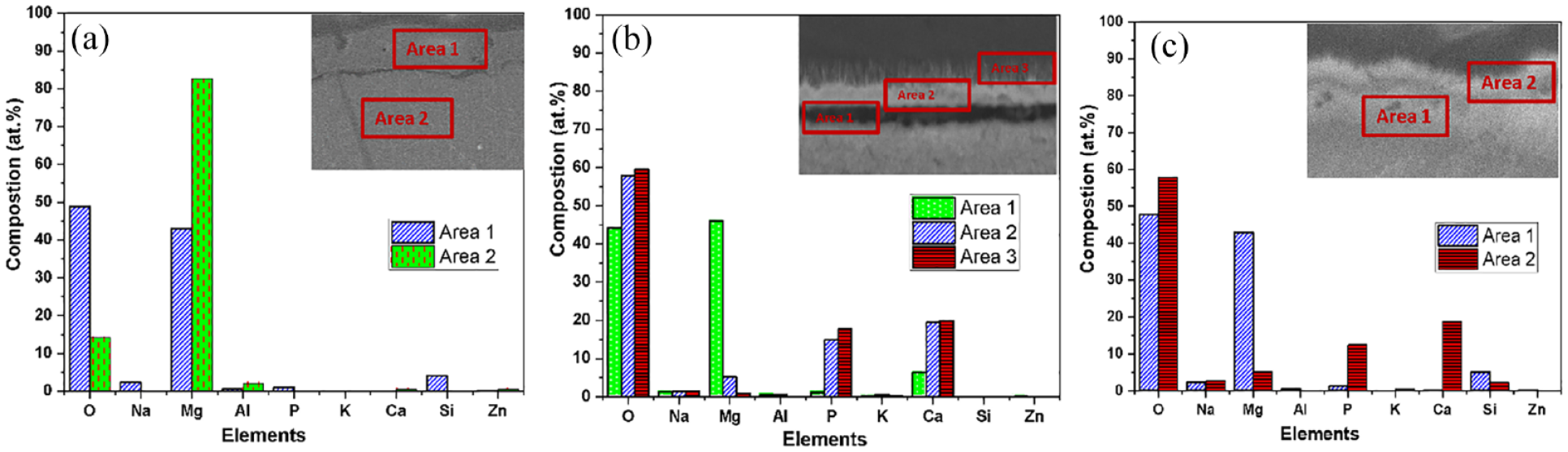
EDS analysis of specimens: (a) 30 V, (b) HAp/AZ31, and (c) HAp/30V/AZ31.
Figure 4(a) illustrates the polarization curves of the specimens immersed in Hank’s Balanced Salt Solution (HBSS) at 37°C. The corrosion potential (Ecorr) and corrosion current density (icorr) were determined using the Tafel extrapolation method with NOVA 1.10 software, and the corrosion rates (CR) were calculated from the polarization curves as presented in Table 2.
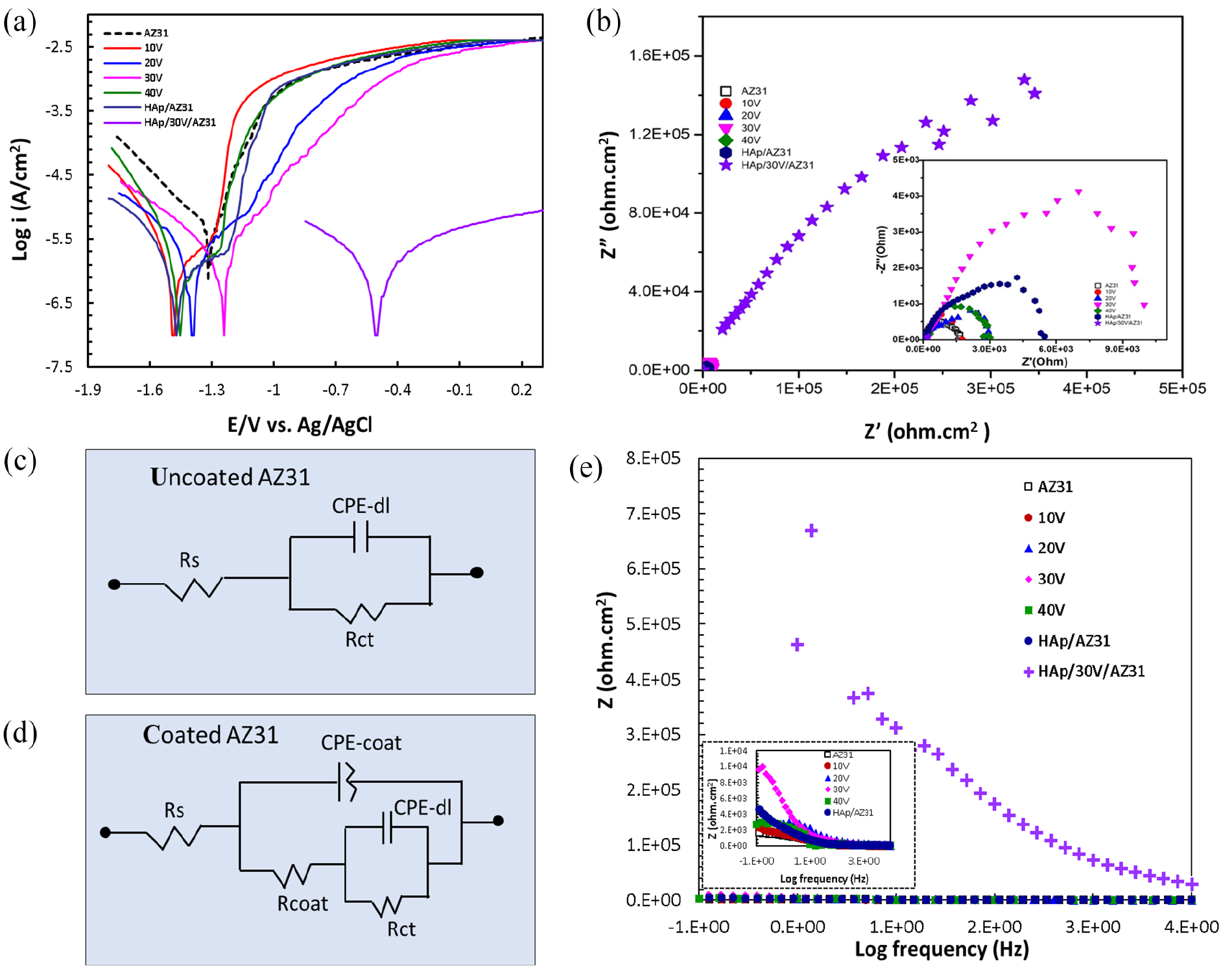
(a) Polarization curves, (b) nyquist impedance spectrum of specimens in HBSS, (c) uncoated AZ31, (d) coated AZ31-equivalent circuits, and (e) bode plot.
Electrochemistry parameters.
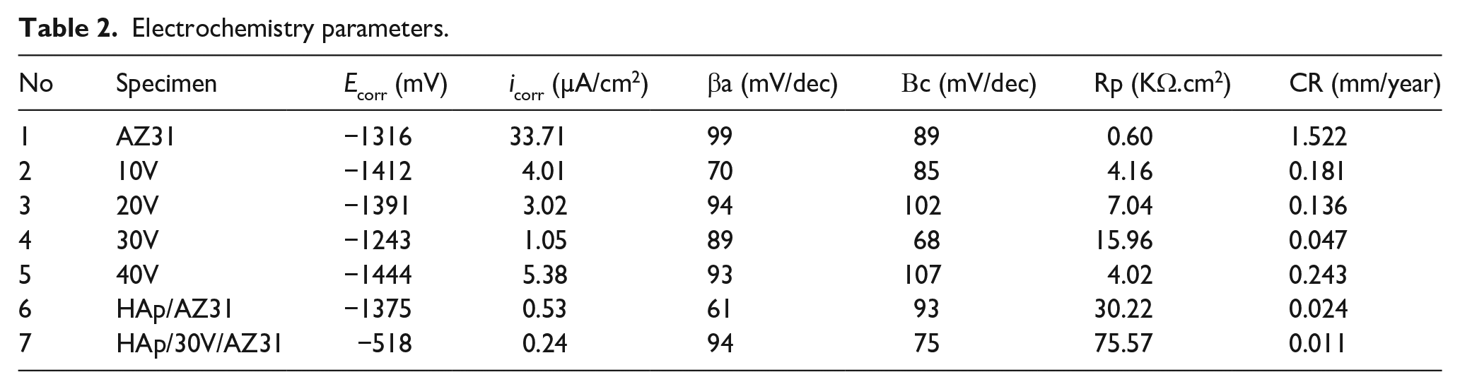
The icorr and Ecorr value for the AZ31 substrate are 33.71 µA/cm2 and −1316 mV. For specimens anodized at different voltages, the icorr values are 4.01, 3.02, 1.05, and 5.38 µA/cm2 and Ecorr values are −1412, −1391, −1243, and −1444 mV for 10, 20, 30, and 40 V specimen, respectively. The Ecorr shifted toward the positive direction with increasing voltage up to 30 V during the anodizing process. These findings confirm that the specimen anodized at 30 V voltage exhibited the highest corrosion resistance. Conversely, at the anodizing voltage of 40 V, the Ecorr value decreased and the icorr value increased, indicating lower corrosion resistance compared to the specimen anodized at 30 V voltage. This can be attributed to the unique structure for the specimen anodized at 30 V voltage. Furthermore, Hydroxyapatite (HAp) coatings with and without an anodizing layer demonstrate a sharp decrease in icorr, reaching 0.24 and 0.53 µA/cm2, respectively. The Ecorr shifted toward the positive direction with low corrosion rates (0.011 and 0.024 mm/year, respectively). In particular, the icorr value of the sample containing both the HAp coating and the anodized layer (HAp/30V/AZ31) is reduced by about 4.4 times compared to the sample with only a single anodized layer of 30 V and 2.2 times for the sample of HAp coating without an anodizing layer.
The significant increase in the polarization resistance (Rp) of the HAp/30V/AZ31 specimen also proves the anti-corrosion effect of the HAp coating with an anodized intermediate layer. Electrochemical impedance spectroscopy (EIS) was employed to investigate the corrosion resistance of AZ31 substrate with and without coatings. Figure 4(b) displays the Nyquist impedance spectrum of the specimens. The determination of corrosion rate is associated with the charge transfer resistance (Rct) using EIS technique, where Rct is equal to the diameter of the semicircle in the Nyquist impedance spectrum. The overall increase in Z’ of the specimens can be attributed to the formation of an inner passive layer and HAp coating. The Z’ value of the AZ31 substrate is 1.75 × 10³ ohm.cm2 and the specimens anodized at 10, 20, 30, and 40 V are 1.80 × 10³, 2.94 × 10³, 10.5 × 10³, and 3.03 × 10³ ohm.cm2, respectively. The Z’ value of the HAp/AZ31 specimen is 6.04 × 10³ ohm. Notably, there is a significant increase in the Z’ value for the HAp/30V/AZ31 specimen, reaching 9.99 × 10⁵ ohm.cm2. This increase in Z’ values is attributed to the formation of the porous ceramic structure of the MgO layer and HAp coating on the AZ31 substrate, which created a protective layer improving the corrosion resistance. An equivalent circuit that explains the impedance data has been displayed to help in understanding corrosion behavior of the coated and uncoated specimens. 36 The equivalent circuit was employed to fit the impedance spectrum, where Rs, CPE, and CPE-dl are the solution resistance, constant phase element, and double layer capacitance, respectively, and Rct and Rcoat are the charge transfer resistance and pore resistance of the surface layer, respectively. The equivalent circuits for uncoated AZ31 and coated AZ31 specimens were shown in Figure 4(c and d). Table 3 was equivalent circuit data.
Fitting results of equivalent circuit elements.
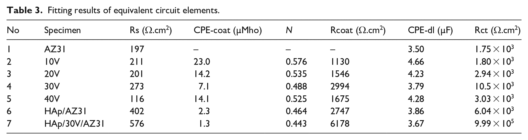
The double layer (CPE-dl) and coating capacitance (CPE-coat) are connected by Rct and Rcoat, respectively. Resistance and capacitance are inversely correlated, as Rcoat increases and CPE-coat decreases, coating’s protective effectiveness improves. Because of their denser structure and highest thickness value of 8.3 µm (5.8 µm of 30 V layer and 2.5 µm of HAp coating), the HAp/30V/AZ31 specimen has a highest overall impedance and offers superior protection than other samples. The high frequency limit, which is also dependent on the resistivities of the solid and liquid phases on the coating, may be the cause of the variation in Rs value. The Bode plot was shown in Figure 4(e). These results indicate a significant improvement in the corrosion resistance of the coated AZ31 specimens compare to the uncoated AZ31 specimen and the combination of both porous ceramic structures of the MgO layer and HAp coatings causes to the best corrosion resistance for the HAp/30V/AZ31 specimen. This is proven through its impedance modulus at a low-frequency and Rct value is the highest.
The SEM images of the surface and cross-section of the HAp/AZ31 and HAp/30V/AZ31 specimens after immersion test for 28 days are shown in Figure 5. Both surface and cross-section images showed deposited corrosion products . The plate-like crystals of the HAp coating underwent a transformation into aggregated clusters, precipitating on the surface of the specimen. The original HA players remained and further low-crystalline HAp deposited on the surface, because both dome-shape particles of inner layer and rod-shape crystals of outer layer were clearly observed under the corrosion product layer with thickness of ~6 µm (Figure 5(a)). Localized corrosion was observed at defects in the coatings and within the AZ31 substrate, where pits exhibited lateral growth, indicated by dark regions with thickness of ~2 µm (Figure 5(b)). Numerous large cracks were observed on both the surface and cross-section of the HAp/AZ31 specimen. In contrast, the microcracked structure of the corrosion product on the surface and a very thin local corrosion layer at the boundary between an anodizing intermediate layer and the AZ31 substrate of the HAp/30V/AZ31 specimen were observed in Figure 5(c and d), indicating a more robust protective layer compared to the HAp/AZ31 specimen.
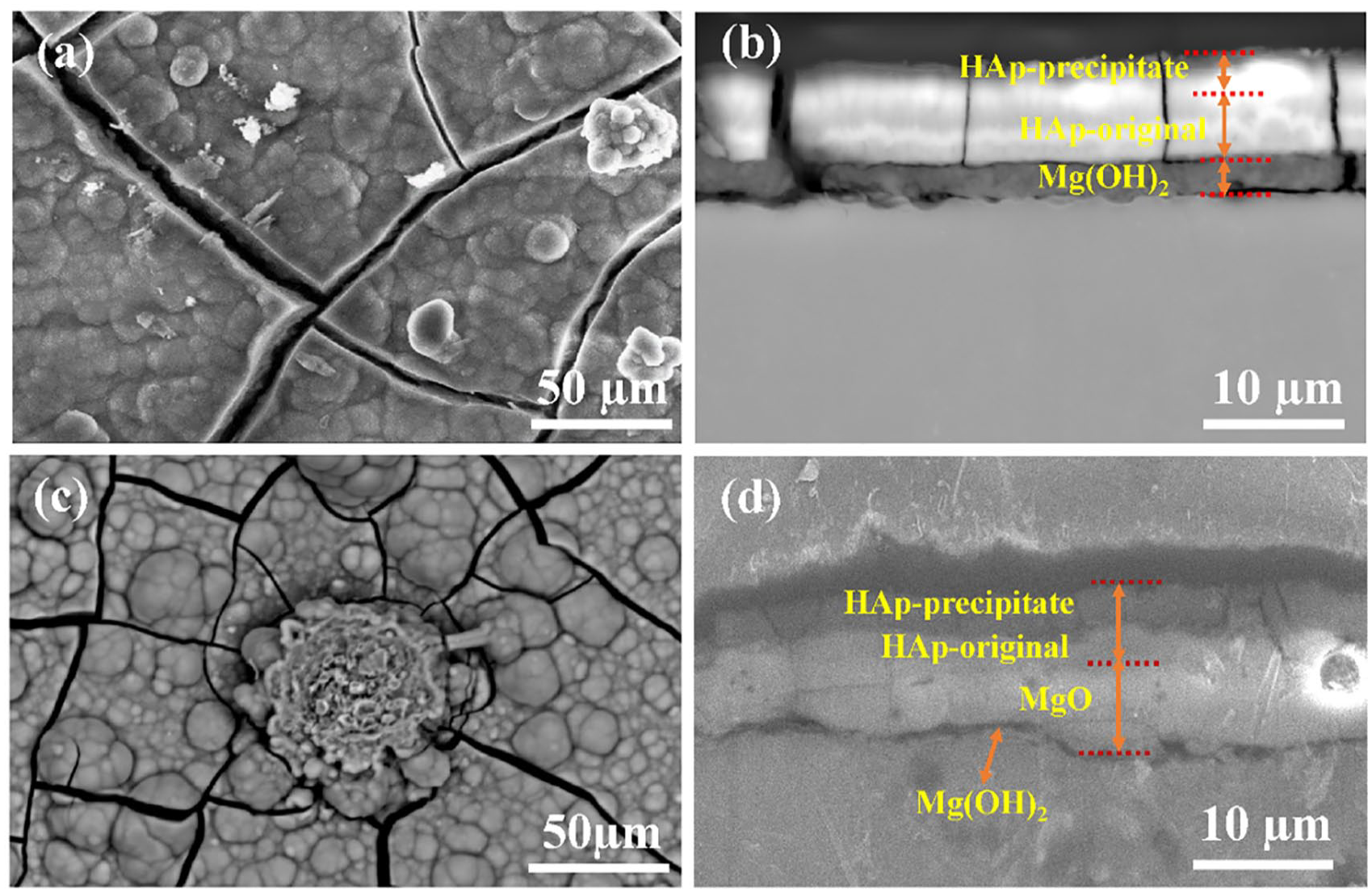
Surface and cross-sectional morphology of the specimens after immersion test: (a and b) HAp/AZ31, (c and d) HAp/30V/AZ31.
Figure 6 shows the Mg2+ ions release rate of the HAp/AZ31 and HAp/30V/AZ31 specimens in HBSS after 28 days. Rapid corrosion occurred on the first day of immersion for both the specimens. Afterwards, the highest Mg2+ ion release rate was observed after 5 days for HAp/AZ31 specimen and 7 days for HAp/30V/AZ31 specimens. Between the 6th day to the 14th day for HAp/AZ31 specimen, the corrosion rate significantly decreased. Subsequently, there was a slight further decrease in the corrosion rate after 14 days of immersion. Throughout the immersion period, the HAp/30V/AZ31 specimens consistently exhibited a much lower corrosion rate compared to the HAp/AZ31 specimen due to the Mg2+ ion release rate of the HAp/30V/AZ31 specimen was notably lower in comparison to the HAp/AZ31 specimen.
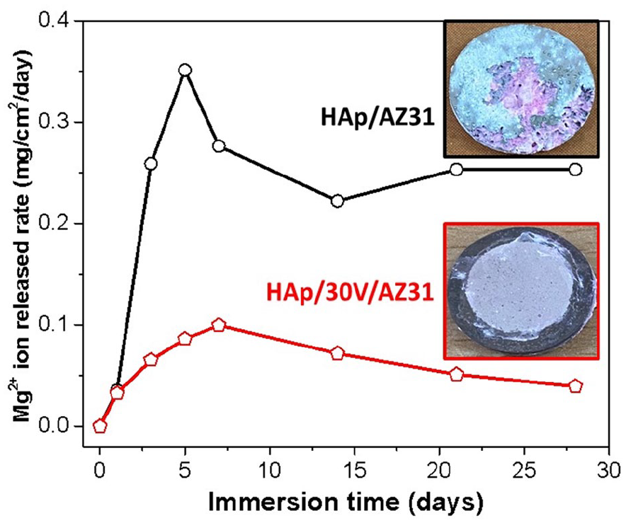
Mg2+ ions release rate of HAp/AZ31 and HAp/30V/AZ31 specimens immersed in HBSS during 28 days.
The adhesion strength of the specimens are depicted in Figure 7. Generally, the adhesion strengths increased with the anodizing voltage in range of 10–30 V, with values of 7.79, 10.68, and 18.78 MPa, respectively.
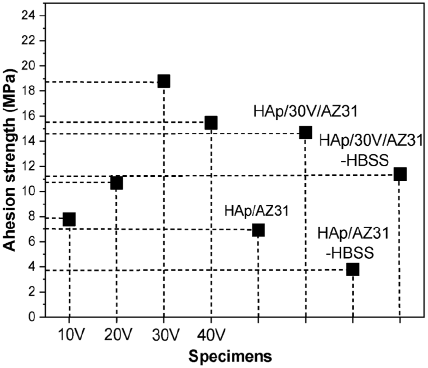
Adhesion strength of the specimens.
The increase in adhesion strength with anodizing voltage is due to the increased thickness of the anodizing layer. Among them, the coated layer of anodizing voltage 30 V has the highest adhesion strength as a results of the outer layer with a more uniform porous structure than other layers and the inner layer being denser. However, the adhesion strength decreased for specimens treated at an anodizing voltage of 40 V. This may be caused by the its uneven porous structure. Additionally, the adhesion strengths of the HAp coatings with and without an anodizing layer were 14.70 and 6.92 MPa, respectively. These results highlight a significant increase in adhesion strength with the presence of the anodizing layer. After the immersion test, the adhesion strengths of the coatings are also determined. The samples were called HAp/AZ31-HBSS and HAp/30V/AZ31-HBSS and the achieved adhesion strengths were 3.78 and 11.38 MPa, respectively. There was a decrease in adhesion strength for both specimens after the immersion test. Specifically, the adhesion strength of HAp/AZ31-HBSS specimens decreased rapidly to 45%, while that of HAp/30V/AZ31-HBSS specimens decreased to 22%. This reduction in adhesion strength of HAp/AZ31-HBSS specimens was attributed to pitting and local corrosion, indicating substrate corrosion during the coating procedure, resulting in a Mg(OH)2 layer. Conversely, the slighter decrease observed in HAp/30V/AZ31-HBSS specimens can be attributed to the presence of a very thin layer of corrosion products generated during the immersion process. In essence, the uniform structure of MgO within the anodizing layer provided protection against corrosion while simultaneously enhancing the adhesion strength of the specimens.
Discussion
The formation mechanism of anodizing layers is complicated due to many electrochemical, chemical and thermal reactions. Key reactions in the anodizing process include oxide film formation, primary film dissolution, and gas evolution on the anode surface. Dominance of any of these reactions depends on magnesium alloy composition, electrolyte type, concentration of each component in the electrolyte and current density, and applied voltage.
The coating’s growth is described by the basic electrochemical reactions (1)–(3) taking place at the metal/electrolyte interface, representing anodic dissolution of magnesium and the formation of Mg(OH)2, MgO:


Moreover, the formations of Mg3(PO4)2 and MgSiO3 are due to reactions of (4) and (5):


Therefore, MgSiO3, Mg3(PO4)2, and MgO were the principal phases within the anodizing layers (Figure 1(a)), aligning with prior studies. 10
The anodizing layers indicate the increase in dimension and thickness of the ceramic structure of the MgO layer as the anodizing voltage increases. This phenomenon is attributed to the fact that at lower anodizing voltages, the external electric field may not be potent enough to consistently breach the protective barrier layer at the base of these pores or holes. Conversely, at higher anodizing voltages, the electrochemical corrosion rate surpasses the chemical dissolution rate, leading to an increase in the average diameter of the pores. Furthermore, the anodizing voltage exceeds the breakdown potential, causing corrosion at the grain boundary, leading to ignition occurring on the surface of the specimen in solution (40 V). In the HAp coating without an intermediate layer indicated some defects on the surface. Additionally, the boundary between the AZ31 substrate and the HAp coating appears a wavy region with relatively dark, suggesting corrosion of the substrate during the coating procedure, likely forming a Mg(OH)2 intermediate layer, as reported by Tomozawa et al.35,37,38 These consisted of Ca, P, and with the atomic Ca/P ratio of 1.64 as shown in our previous study.30,32 Thickness of both HAp coating and Mg(OH)2 layers closest the substrate increases and reached ~6 and ~2 µm, respectively. Those corrosion products with many large cracks causing a decrease in adhesion, simultaneously showing the fast biodegradation rate of hydroxyapatite coated AZ31 alloy without intermediate layer in HBSS. In contrast, samples with an intermediate layer only observed an increase in the outer HAp layer while the inner layer close to the substrate hardly thickened after the immersion test. This proves that the inner anodized layer has the effect of protecting against corrosion for HAp/30V/AZ31 material and has been observed in Figure 5(d). During the immersion process, in the early stages, the substrate degradation rate is faster in about 5–7 days. After that, the degradation rate decreased because the layer of corrosion products created a barrier layer, leading to limiting the intense corrosion of sample HAp/AZ31 (Figure 6). Meanwhile, throughout the immersion period, the HAp/30V/AZ31 specimens consistently exhibited a much lower corrosion rate compare to the HAp/AZ31 specimen. This can be attributed to the combination of the porous ceramic structure of the MgO layer with thickness of 5.7 µm and the HAp coating with thickness of 2.5 µm. Therefore, its corrosion resistance are significantly improve compare to both the separate anodizing and HAp layer. Where, deposition of HAp coating on anodizing layer results in the reduction of surface and structural defects by filling the gaps, and small holes of porous ceramic structures MgO of the anodizing layer. Simultaneously, anodized layer inside of HAp/30V/AZ31 acts as a barrier for its protective effectiveness improves.Therefore, they collectively prevent the diffusion of the Hank’s balanced salts solution. Furthermore, the results of adhesion test using the pull-off method also show a significant improvement with existence of an anodizing intermediate layer as shown in Figure 7. This is because of a uniform porous structure with a pore size of <1 µm of an anodizing layer, which not only creates pins that help HAp grow inside but also has enough protection ability for HAp/30V/AZ31 material. The result is a significant improvement in adhesion strength and achieved ~14.70 MPa compared to ~6.92 MPa of the HAp coated AZ31 alloy without an anodizing intermediate layer. Figure 8 shown the cross-section optical images after adhesion test of specimens before and after immersion in HBSS for 28 days. Before immersion, At HAp/AZ31-specimen have a wavy structure was observed as shown in Figure 8(a). While, at HAp/30V/AZ31-specimen a wavy structure with smaller amplitude was observed as shown in Figure 8(b). After immersion test, specimens appeared larger corrosion areas as in Figure 8(c and d). Aspecially, at HAp/AZ31-HBSS-specimen, there are large corroded areas with depth holes of hundreds of micrometers. That is the reason for the rapid decrease in adhesion strength of the coating after immersion in HBSS solution to 45%. The decrease of adhesion strength values of the specimens after immersion test was not only explained by the effect of localized corrosion but also due to the deposition of low-crystalline HAp on the original HAp layer. That could be increase the compressive residual stress of the HAp layer led to presumably weaken the adhesiveness of the HAp layers. The slighter decrease in adhesion strength of HAp/30V/AZ31-HBSS-specimen to 22% is due to the contribution of an anodizing intermediate layer.
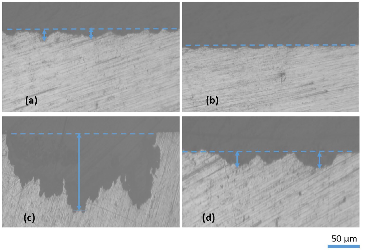
Optical images after adhesion test of specimens in HBSS for 28 days: (a) HAp/AZ31-specimen, (b) HAp/30V/AZ31-specimen before immersion, (c) HAp/AZ31-specimen, (d) HAp/30V/AZ31-specimen after immersion.
On the other hand, according to ISO 13779–2:2008, the adhesion strength of coating should not be less than 15 MPa for permanent implant such as artificial joints. 39 Therefore, an anodizing intermediate layer was performed at 30 V by anodizing process combines HAp coating deposited on AZ31 alloys at 90°C, pH solution of 7.5 by chemical solution treatment method for 2 h can be suitable for applications as biodegradable material.
Conclusions
HAp coatings were successfully prepared in an ethylenediaminetetraacetic acid calcium disodium salt hydrate (Ca-EDTA: C10H12N2O8Na2Ca) and potassium dihydrogen phosphate (KH2PO4) at 90°C and pH solution of 7.5 by chemical solution treatment method for 2 h. Additionally, an intermediate layer was prepared by the anodizing process in the electrolyte anodization bath with the chemical composition consisting of 1 M NaOH; 0.5 M Na2SiO3 and 0.05 M Na3PO4 solution and performed at various anodizing voltage for 600 s. Obtained results indicated a significant improvement in corrosion resistance and adhesion strength of HAp coated AZ31 alloy with the existence of an anodizing intermediate layer, which is attributed to the uniform porous ceramic structure of MgO layer. The corrosion rate of the HAp coating with an anodizing layer decreased 4.4 times (0.011 mm/year) and the adhesion strength increased about two times compared to the HAp coating without an anodizing layer. This is suggestion that an anodizing intermediate layer was peformed at 30 V can be beneficial to improve the properties of the HAp coating deposited on AZ31 alloys and it is suitable for applications as biodegradable material.
Footnotes
Author contributions
Anh Tuyet Thi Ngo contributed to this work in experiment planning, experiment measurements, data analysis and manuscript preparation. Duong Van Luong, Linh Do Chi, Hanh Hong Pham and San Thy Pham contributed to the manuscript preparation.
Declaration of conflicting interests
The author(s) declared no potential conflicts of interest with respect to the research, authorship, and/or publication of this article.
Funding
The author(s) disclosed receipt of the following financial support for the research, authorship, and/or publication of this article: This work was funded by the Vietnam Academy of Science and Technology (VAST) under Grant number VAST03.02/22-23.