
Abstract
Exploring high strength materials with a higher concentration of reinforcements in the alloy proves to be a challenging task. This research has explored magnesium-based composites (AZ31B alloy) with tungsten carbide reinforcements, enhancing strength for medical joint replacements via league championship optimisation. The primary objective is to enhance medical joint replacement biomaterials employing magnesium-based composites, emphasising the AZ31B alloy with tungsten carbide reinforcements. The stir casting method is utilised in the manufacture of magnesium matrix composites (MMCs), including varied percentages of tungsten carbide (WC). The mechanical characteristics, such as micro-hardness, tensile strength, and yield strength, have been assessed and compared with computational simulations. The wear studies have been carried out to analyse the tribological behaviour of the composites. Additionally, this study investigates the prediction of stress and the distribution of forces inside bone and joint structures, therefore offering significant contributions to the field of biomedical research. This research contemplates the use of magnesium-based MMCs for the discovery of biomaterials suitable for medical joint replacement. The study focuses on the magnesium alloy AZ31B, with particles ranging in size from 40 to 60 microns used as the matrix material. Moreover, the outcomes have revealed that when combined with MMCs based on AZ31B-magnesium matrix, the WC particle emerges as highly effective reinforcements for the fabrication of lightweight, high-strength biomedical composites. This study uses the league championship optimisation (LCO) approach to identify critical variables impacting the synthesis of Mg MMCs from an AZ31B-based magnesium alloy. The scanning electron microscopy (SEM) images are meticulously analysed to depict the dispersion of WC particulates and the interface among the magnesium (Mg) matrix and WC reinforcement. The SEM analysis has explored the mechanisms underlying particle pull-out, the characteristics of inter-particle zones, and the influence of the AZ31B matrix on the enhancement of the mechanical characteristics of the composites. The application of finite element analysis (FEA) is being used in order to make predictions regarding the distribution of stress and the interactions of forces within the model of the hip joint. This study has compared the physico-mechanical and tribological characteristics of WC to distinct combinations of 0%, 5%, 10% and 15%, and its impact on the performance improvements. SEM analysis has confirmed the findings’ improved strength and hardness, particularly when 10%–15% of WC was incorporated. Following the incorporation of 10% of WC particles within Mg-alloy matrix, the outcomes of the study has exhibited enhanced strength and hardness, which furthermore has been evident by utilising SEM analysis. Using ANSYS, structural deformation and stress levels are predicted, along with strength characteristics such as additional hardness of 71 HRC, tensile strength of 140–150 MPa, and yield strength closer to 100–110 MPa. The simulations yield significant insights into the behaviour of the joint under various loading conditions, thus enhancing the study’s significance in biomedical environments.
Introduction
The MMCs are flexible materials used in a variety of industries, including automotive engineering, aviation, and both light and heavy industries.1 –3 Magnesium, recognised as one of the lightest metallic elements with structural characteristics, has remarkable strength and stiffness, making it a viable alternative to standard alloys in instances where weight reduction is required.2 –4 Magnesium’s ability to absorb hydrogen via the creation of hydrides renders it a potential future energy source.1,2 There has been a considerable concentration in recent times on investigating thin yet robust metallic materials for potential application. In recent years, there has been dedicated research of strong metallic materials, with a variety of steel compositions and their mixes revealing utility in a wide range of applications such as home construction and vehicle production.1,2 Despite the excellent strengths of steel mixtures, there is an increasing trend towards the use of light metal combination systems, which are regarded, suited for specific applications due to their commendable strength characteristics.3 –5 This is particularly noticeable in instances where steel combinations have typically dominated due to their strong strength characteristics.
Bergmann et al. conducted a study on hip joint loading during walking and running, using data from two patients. 1 Their research provided valuable insights into the mechanical stresses experienced by the hip joint during different activities. In another study by Bergmann et al., explored the influence of shoes and heel strike on hip joint loading. 2 This research shed light on how footwear and gait patterns affect the biomechanics of the hip joint. Bergmann et al. also investigated the risk of hip implant fixation during staircase walking, as detailed in their study. 3 Their findings contributed to the understanding of factors influencing the stability of hip implants. Another related research by Bergmann et al.’s, where the primarily analysis has focused on hip joint forces during load carrying. 4 This study provided valuable data on the mechanical demands placed on the hip joint during activities involving load-bearing.1 –4
Chang et al. presented research on the robust optimisation of total joint replacements, incorporating environmental variables. 5 This work addressed the challenges of designing joint replacements that can withstand varying conditions. Bergmann et al. examined hip contact forces and gait patterns from routine activities in their study. 6 Their research offered insights into the forces acting on the hip joint during daily movements. Katoozian and Davy investigated the effects of loading conditions on the three-dimensional shape optimisation of femoral components for hip endoprostheses. 7 Their research has contributed to the design of enhanced hip implants. A literary study examined outcomes for proximally cemented, axially uncemented complete hip arthroplasty with a minimum follow-up duration of 24 months. It was discovered that the initial failure rates for these prostheses were considered unsatisfactory for an advanced hip design. 7 Chang et al. conducted finite element model experiments with environmental variables to design and analyse robust total joint replacements. 8 Their work has addressed the significance of considering environmental factors in joint replacement design5 –8
A comparative examination of stresses within the proximal femur is performed using finite element modelling. Test has compared several geometries of hollow stems to solid stems, each with a different elastic modulus.9 –12 The research looks at the biomechanical primary stability of two different side plate fixation devices: the Sliding Hip Screw (SHS) with an extra derotation screw and the Percutaneous Compression Plate (PCCP). 13 Assessment is carried out using an unstable intertrochanteric cadaver model and study looks at the displacements of the proximal head fragment during cyclic loading and the load to failure characteristics of both implant types.14 –16
Optimised ceramic hip joint ball head proof test to detect and reject faulty samples on the manufacturing line. With plane strain elements, a 2D Finite Element (FE) model of the acetabulum was built with four layers-plastic, cement, graft, and bone. The interior acetabular cup diameter was 50 mm. A FE model was generated utilising ABACUS software to examine the dislocation phenomena. The outcomes of the analysis revealed that the newly developed design exhibited a 28% rise in resistant force buildup during dislocation. The plastic, cement, and bone layers were linear elastic, whereas the graft layer was elasto-plastic. Improved cementless femoral hip joint prosthesis dependability was achieved by optimisation. This required optimising the prosthesis’s design and structure for performance and durability.17 –19
A stiffer prosthesis material caused the maximum contact stress at the stem’s distal end, according to Finite Element (FE) study on a three-dimensional (axisymmetric) model. A flexible implant like UHMWPE-Al2O3 has a high interface stress at the proximal end. This showed that a more flexible stem or less rigid materials transferred greater weight to the proximal end. 20 Developed a numerical optimisation method for a fibre-reinforced composite implant to minimise bone remodelling and stress shielding. The study used failure-based and stress shielding-based design objectives to optimise a carbon fibre-reinforced composite implant. 21 Assessed Finite Element (FE) modelling in three critical areas: skeletal structure analysis, orthopaedic device analysis and design, and tissue growth analysis. 22
Silicon Carbide particles (SiCp) were tested on AZ61 alloy composite fatigue life and strength. SiCp reduced fatigue life and composite strength, the study found. 1wt% SiCp improved mechanical and fatigue performance over pure AZ61 magnesium alloy and AZ61 composite with 2 wt% SiCp. 23 The AZ61/Al2O3/SiC hybrid composite was examined after two Equal Channel Angular Pressing (ECAP) runs. The Hall-Petch strengthening mechanism improved the mechanical characteristics of AZ61 hybrid composites, according to the investigation. 24 Stir casting SiC nanoparticles into a magnesium alloy created a nano-composite with homogeneous nanoparticle distribution. Stir-cast nano-composites like the AZ31-SiC nano-composite are rare, according to our research. 25 Adding 1% SiCp to AZ61 magnesium alloy and AZ61/2wt%SiCp composite increased mechanical and fatigue performance. SEM fracture surface tests validated SiCp’s role in shaping the composite’s mechanical and fatigue characteristics. 26
The effects of friction stir processing (FSP) and friction stir vibration processing (FSVP) on the mechanical and microstructural properties of AZ91 magnesium alloy with added SiC nanoparticles are investigated. By comparing the microstructures in the nano-composite layers produced by FSVP and FSP, it can be seen that the former produces finer microstructures and a more even distribution of nanoparticles. The study finds that when the number of FSP passes rises, the porosity content decreases. Additionally, it should be highlighted that samples processed using FSP have samples with a compressive strength that is inferior than composites processed using FSVP. The results demonstrate that increasing vibration frequency during FSVP reduces particle clumping by causing composite particles to disperse more uniformly.27 –30
The present study has aimed to examine the implications of vibration on the AZ91 composite layers that are fabricated using a modified “friction stir technique.” 27 The microstructure and mechanical characteristics of the composite layer are considerably affected by the inclusion of vibration, which is generated by a motor placed below the work-piece. The modification arises as a result of enhanced strain rate, deformation, and expansion inside the material flow zone. When comparing the tensile strength of samples treated utilising “friction stir vibration” (FSVP) with those processed solely with “friction stir” (FSP), it was discovered that the tensile strength raised from roughly 203 MPa to around 234 MPa. 27 The introduction by the FSVP resulted in a more uniform dispersion of “silicon carbide” (SiC) particles, hence reducing the possibility of particle clustering or agglomeration. As a result, the wear resistance of the samples treated with FSVP outperformed that for the traditionally processed samples and the base metal. 27
The wear processes found within the scope of this study are delamination, oxidation, abrasion, and plastic deformation. 27 Additionally, both specimens subjected to FSP and FSVP techniques shown a significant reduction in the volume of hydrogen evolution during immersion, in comparison to the base metal. Furthermore, it was observed that the corrosion resistance demonstrated by the sample subjected to “Friction Stir Vibration Processing” (FSVPed) was notably superior to that of the specimens subjected just to “Friction Stir Processing” (FSPed), as well as the base metal. The noticed enhancement of corrosion resistance underscores the potential merits of employing vibration throughout the manufacturing process. The application of vibration through the motorised fixture positioned below the work-piece was a crucial factor in influencing the mechanical, corrosion, and wear characteristics of the AZ91 composite layers. Significantly, the use of vibration resulted in notable enhancements in tensile strength, wear resistance, and corrosion resistance, primarily due to the raised strain rate, deformation, and expanded material flow zone. The superior mechanical and wear performances of the FSVPed samples can be ascribed to the homogeneous dispersion of SiC particles. The research study offers significant contributions to the field of composite materials optimisation, with a particular focus on the role of vibration in enhancing their overall performance and durability. 27
Another study has aimed to conduct a comparative examination of AZ91 specimens that were subjected to traditional FSP and those that have been treated with a modified version referred to as FSVP. 28 Both methods are utilised for the purpose of generating surface composites on the metallic substrate. The study also examines the influence of FSP/FSVP pass count on distinct sample characteristics. The findings indicate that the incorporation of workpiece vibration in FSVP leads to a raised degree of material deformation and stirring inside the stir zone, as compared to FSP. The primary observations encompass, during the FSP, it has been demonstrated that silicon carbide (SiC) particles have a tendency to agglomerate inside the AZ91 magnesium alloy matrix. Nevertheless, the aforementioned tendency experiences a notable reduction when the FSVP technique is employed, resulting in a more homogeneous dispersion of silicon carbide (SiC) particles. 28
The dissolution of the b-phase appears to be more pronounced in the stir zone during friction stir vibration compared to the standard friction stir technique, mostly due to high temperatures. 28 The examination of microstructure in specimens subjected to the processes of FS and FSV reveals a reduction in grain size when the FSVP technique is employed. 28 The aforementioned reduction becomes more significant when the quantity of passes rises. 28 The samples which have undergone the FSV process demonstrate superior mechanical performance compared to those that have been treated with FS. 28 Furthermore, it has been displayed that both FS and FSV treated specimens exhibit enhanced mechanical characteristics as the number of processing passes rises. 28 The study offers more insight that the microstructures of samples treated with FSVP experience significant modifications as the frequency of vibration rises. 28 The enhancement of material deformation and movement inside the stir zone is facilitated by a higher vibration frequency, resulting in a reduction in the agglomeration of SiC nanoparticles. This observation highlights the impact of vibration frequency on the material’s performance across the various phases of processing. 28
Another comparable study where a modified technique, called “FSVP” was applied to develop surface composites on the AZ91 magnesium alloy. 29 In this experimental approach, SiC particles of nano-scale dimensions, namely measuring 30 and 300 nm, were employed as agents for reinforcement. The present study aimed to examine the influence of workpiece vibration and the size of reinforcing particles on the microstructure and mechanical characteristics of AZ91 composite layers. The findings of the study demonstrated that the introduction of vibration in FSVP contributed to a reduction in the size of grains within the stir zone. Additionally, this caused an additional uniform dispersion of reinforcing particles throughout the material. 29 The samples subjected to FSV exhibited raised hardness, strength, and ductility as a consequence of enhanced dynamic recrystallisation in comparison to the specimens processed employing FS. The specimens subjected to FS exhibited a tensile strength of around 204 MPa, whereas the specimens processed utilising FSV displayed a rise in tensile strength to roughly 232 MPa, without the presence of SiC reinforcing particles. 29
The impact of minuscule SiC particles with a size of 30 nm on mechanical characteristics has been proven to exceed that of bigger SiC particles measuring 300 nm. 29 The research findings indicated that there was a more even uniformly dispersion of smaller reinforcing particles in both FSP and FSVP processes, in contrast to the larger particles. As a consequence, the readings of ductility and formability index exhibited a rise, with FSV-processed specimens comprising larger SiC particles (300 nm) displaying about 22% and 6873 MPa·% respectively, whereas FSV-processed specimens comprising smaller particles (30 nm) exhibited approximately 26% and 10,072 MPa·% respectively. 29 The implications of FSVP on the microstructure and mechanical characteristics demonstrated to be positively correlated with the rise of vibration frequency. 29 The hardness values noticed in the stir zone exhibited a rise of approximately 116 MPa for specimens processed utilising FSV with a vibration frequency of 25 Hz to approximately 157 MPa for specimens subjected employing FSV with a vibration frequency of 50 Hz. 29 As the frequency of vibration raised specimens treated by FSV revealed a rise of tensile residual stresses in the stir zone. 29 This discovery highlights the significance of vibration frequency for determining the mechanical characteristics of the material under consideration. 29
Another related study has investigated the use of the small-hole drilling method (SHDM) on AZ91 alloy, examining both the FSP and FSVP approaches utilising a novel three-dimensional numerical analysis. 30 The focus of this analysis includes multiple facets such as chip formation, stress distribution, and the drilling process. Moreover, a comprehensive examination of the mechanical characteristics and microstructure of the treated samples utilising FSP and FSVP processes was carried out, resulting in notable breakthroughs. 30 Throughout every step of the method, an intended reduction in rotational velocity was carried out, which caused a reduction in input thermal energy and subsequently leading to the refinement of the grain size from 49 to 28 μm. 30 This modification significantly enhanced the mechanical characteristics. On the other hand, raising the traverse speed led to enhanced grain refinement, which led to a reduction in size from 42 to 22 μm. The enactment of this modification had an essential impact in enhancing the mechanical characteristics as a consequence of a raised rate of cooling. 30 Furthermore, the FSVP technique revealed significant material deformation in the stir zone, exceeding that of FSP. 30 The observed rise in deformation not only contributed to an enhancement in the ductility ratio (DR), however it also stimulated the formation of smaller grains inside the stir zone, with an average size of roughly 17 μm. 30 When comparing the mechanical characteristics, it was discovered that the specimens treated with FSV exhibited higher strength and hardness values, measuring 251 and 92 MPa, respectively. 30 On the other hand, the specimens treated by the FS technique exhibited more pronounced performance, with a reported strength of 183 MPa and a hardness of 67 MPa. 30 The study additionally included a thorough assessment of the SHDM utilising the 3D finite element approach, with the findings being confirmed by experimental examination of chip production and morphology. 30 It is worth mentioning that the FSVP approach consistently produced fragmented discontinuous chips under distinct conditions. The observed phenomena can be attributed to the raised hardness of samples subjected to FSVP in contrast to specimens exposed to FSP. 30 Additionally, the study exhibited a significant reduction in cutting forces for samples subjected to FSP compared to those subjected to FSVP, regardless of the specific parameters employed. 30 The reduction in size may be ascribed to the enhanced stirring action, raised strain rate, and the superior mechanical characteristics that are characteristic of the samples treated with FSVP. various findings elucidate the complex dynamics associated with various drilling techniques. 30
The optimal tensile strength was obtained with 5% B4C reinforcement. The composites were recognised as consisting of AA2014 and B4C, as validated by X-ray diffraction (XRD) analysis, with no intermetallic present. The presence of WC particles increased mechanical qualities such as tensile strength, hardness, and wear resistance, but at the expense of lower machinability, according to experimental results. 31 The stir casting technique was used to create magnesium matrix composites with the goal of generating strong structural bonding and increased grain strength. The magnesium is added to the alloy matrix components during a melting process using an electric furnace. Successfully created a composite with a well-established metal matrix that can be placed in predefined shapes and sizes by using intensive churning. 32 The primary goal of this research is to create a long-lasting biomaterial for medical applications, namely to form complex bone formations of various sizes and shapes. To achieve this purpose, extra emphasis is paid to improving the chemical makeup of the material to ensure a strong connection, a critical component in the construction of orthopaedic parts meant for interaction with bodily tissues.
The initial step of this study includes the analysis of several materials, including Al2O3, SiC, Al2O3+SiC, TiC, and WC, for the reinforcement of magnesium matrix composites (MMCs), based on insights from literature reviews. Stir casting, a frequently employed process for several composites, was being utilised. Following the fabrication process, the composites were tested for strength and hardness, which revealed that tungsten carbide (WC) particle constituents have performed efficient. Based on these aforementioned characteristics, the WC particles was chosen as the reinforcing-constituents for Mg-based MMCs in this study. In addition, the WC reinforcing-particulates has commonly been employed for the fabrication of biocomposites. The utilisation of a stir casting process in this study has facilitated the fabrication of WC/AZ31B-based Mg-matrix composites, enhancing their structural integrity, durability, strength, adhesion-bonding, and grain strength. The WC/AZ31B-based magnesium-matrix composites have been effectively fabricated by the stir casting technique in order to attain superior physico-mechanical, structural stability, adhesion-bonding, and grain strength. Effective stirring has aided in the development of a homogenously-dispersed and efficient interfacial-adhesion bond-strength based composites with a metal-matrix that can be precisely deposited in specified shapes and sizes. To summarise briefly, the underlying aim of this investigation is to contribute to the development of a high strength, durable, etc., biocomposites for biomedical applications. A complete examination of the mechanical properties was carried out concurrently with the ANSYS predictions and optimisations.
The present work has offered an innovative methodology for enhancing the mechanical characteristics for AZ31B magnesium alloy through the incorporation of WC particles employing the stir casting process. The approach outlined herein offers a practicable, feasible, and economically viable way to fabricating magnesium matrix composites (MMCs). The use of WC, a particulate renowned for its exceptional hardness, significantly enhances the mechanical characteristics of the developed composites. A thorough investigation to the microstructural changes and the dispersion arrangement of WC particles inside the magnesium matrix provide significant insights.
Furthermore, the study thoroughly examines several aspects of the experiment, encompassing material characterisation, fabrication methods, and comprehensive mechanical, tribological, and microstructural evaluations. The employment of advanced techniques such as SEM, X-ray diffraction (XRD) analysis, and FEM simulations exemplifies a rigorous approach in comprehending the mechanical characteristics of materials across various levels. The experimental setup was meticulously controlled, encompassing factors such as load, sliding velocity, and sliding distance, in order to ensure the reliability/dependability of the attained findings.
Moreover, the uniqueness of this study is in the combination of AZ31B magnesium alloy-matrix and WC particles. The meticulous choice of these components, when combined with the stir casting technique, yields composites that exhibit enhanced mechanical and tribological characteristics. The analysis of bone joint structures and the simulation of forces as well as stresses contributes to the uniqueness of this research, as it delves into prospective applications within the realm of biomaterials.
All in all, this research explores the development of robust biomaterials for medical joint replacements, focusing on magnesium-based composites using the AZ31B alloy reinforced with tungsten carbide (WC). The study employs league championship optimisation to enhance the strength and performance of these composites. Results show significant improvements in strength and hardness, particularly with 10%–15% WC reinforcement. Scanning electron microscopy validates these findings. ANSYS simulations predict structural behaviour, highlighting increased hardness (71 HRC), tensile strength (140–150 MPa), and yield properties (100–110 MPa). The study showcases WC as a superior reinforcement material for magnesium-based composites, with potential applications in lightweight, high-strength biomedical devices.
Experimentation
Materials and methods
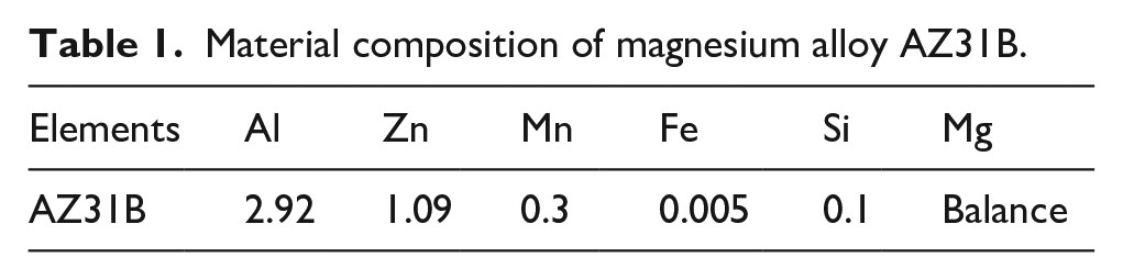
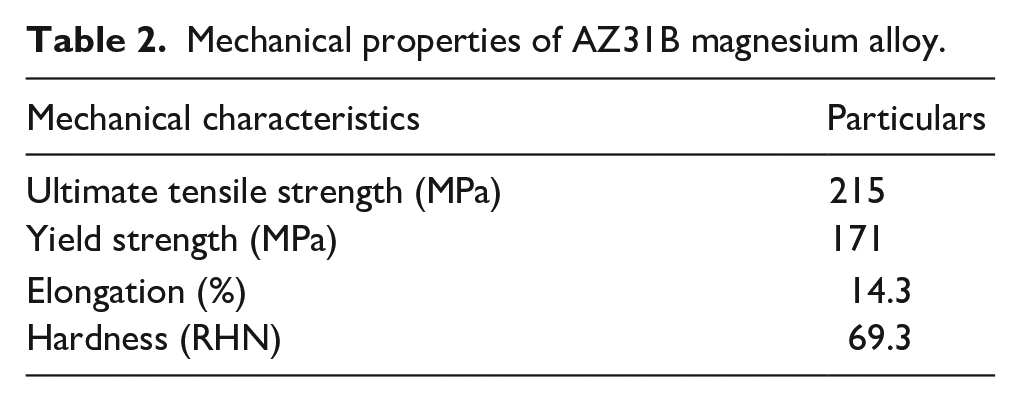
The AZ31B magnesium alloy is used as the matrix material in this proposed experiment, with particle sizes ranging from 40 to 60 microns. The investigation emphasises on the utilisation of WC as reinforcing materials within the Mg-alloy-matrix. Tables 1 and 2 have exhibited the relevant material parameters and mechanical properties. The matrix and reinforcing materials are blended in various proportions: 100%:0%, 95%:5%, 90%:10%, and 85%:15%. The following process, and techniques have been employed in the experiment: first, the magnesium-matrix is melted, then, the reinforcing components are powdered. Following that, the constituent elements have been mixed, and, then, kept molten at a temperature of 650°C. 4 The resulting mixture is then spun continuously at 400 rpm for 4 min. Finally, a distinct mixture is poured or placed into a separate prepared mould, and the developed composite is being tested.
Material composition of magnesium alloy AZ31B.
Mechanical properties of AZ31B magnesium alloy.
Stir casting technique
The stir casting process entails the use of a stirrer that facilitates the blending of particulates into the molten metal.7 –9 All in all, the stir casting method has employed the stirrer to mix the reinforcing-particles into hot molten metal. The primary factors associated with stir casting technique is the settlement or movement of reinforcing particles, the interaction among the reinforcing phase as well as matrix materials, and the formation of agglomerations or clustering of the reinforced particles. The limitations resulting from the incorporation of reinforcing particles can be mitigated by utilising a semi-solid state as the foundation for the metallic matrix. Hence, the stir casting processes depend on reinforcing particle settling, matrix material reactivity, and particle agglomeration. Reinforcing particle amalgamation is possible with the semi-solid metallic matrix. Stir casting phases have been depicted in Figure 1. The stir casting process is extensively employed for nonferrous materials such as Aluminium, Magnesium, and Titanium. However, it is notable that these materials possess relatively low melting temperatures, typically about 500°C, which may be considered inadequate for certain applications. The majority of nonferrous classes have the capacity of withstanding temperatures of up to 650°C. In this particular instance, the temperature is sufficient to cause the transformation of the material into a state of molten form. The stir casting method doesn’t possess the potential of causing melting for the given material. Therefore, the nonferrous materials including aluminium, magnesium, and titanium melt below 500°C, which is appropriate for stir casting. However, most nonferrous grades can sustain the 650°C. Thus, stir casting can attain the molten states in such materials at its temperature limit. Keep in mind that stir casting cannot melt these materials. Instead, a very fine/minute particles of these WC constituents can be deposited and then mixed within the structure of nonferrous castings. The WC particles have been melted around 2870°C.

Flowchart for stir casting process.
The electrically powered furnaces have a capacity of 2500°C. The utilisation of helium gas has been recommended to create an inert gas environment. The furnace is entirely enveloped/encased in an outer covering or an additional layer of coated material. Thereby, the furnace is fully coated, and alloying elements are preheated at 400°C in a controlled environment to remove moisture. The matrix-material melts, and a graphite module has then added a slight strength. The stir casting technique was employed, wherein a graphite stirring apparatus driven by a motor was utilised to ensure the uniformly homogeneous dispersion of reinforcements throughout the hot molten alloy of slag in the furnace. All in all, the stir casting utilises a motor-connected graphite stirrer to evenly mix reinforcements and alloy molten slag in the furnace. This method heats magnesium alloy and tungsten carbide in crucibles utilising muffle furnaces. Controlling the speed and position of mechanised stirring of hot magnesium alloy with WC particles. A control unit controls boiler temperatures, while a display monitors them. Stir casting has involved mechanically swirling a dispersion phase (short fibres and ceramic particles) with a molten Mg-alloy matrix metal to develop a liquid-state composite. Developing Magnesium-based composites has commenced with raw components. Weight- and volume-wise, Magnesium-based composites are the frequently employed MMCs. The thermal stability, wettability, and density are utmost significant when choosing magnesium reinforcing material. High wettability makes WC a good magnesium reinforcer. Magnesium matrix-WC reinforcement ratios have included, 100%:0%, 95%:5%, 90%:10%, and 85%:15%. 5
Experimental procedure
The matrix material is AZ31B magnesium alloy, while the reinforcement material is WC particles ranging in size from 40 to 60 microns. The mixing process, which included AZ31B with 0%, 5%, 10%, and 15% WC, was carried out in a bottom-pouring electrical resistance furnace.
Based on the details provided in the schematic layout, the practical setup for producing composite materials is developed. The maximum temperature and stirrer speed of the furnace are set at 1000°C and 400 rpm, respectively. The furnace is rectangular in shape with a round aperture, and it is covered by semi-cylindrical ceramic bricks with two stages. Mg is cast within a confined chamber with stirring devices at the chamber’s centre. While maintaining a constant temperature of 650°C, the molten magnesium is blended with required weight proportions of WC particles. After 4 min of stirring at 400 revolutions per minute, the Mg-WC melt is poured into a prepared mould. Stirrer speed is controlled by a speed controller, as shown in Figure 2(a) and (b) with a mechanical control mechanism. A vacuum pump is used to create a vacuum within the metallic crucible, a die holder is used to prevent oxidation in the molten metal, and inert gases are injected into the crucible and die holder area.
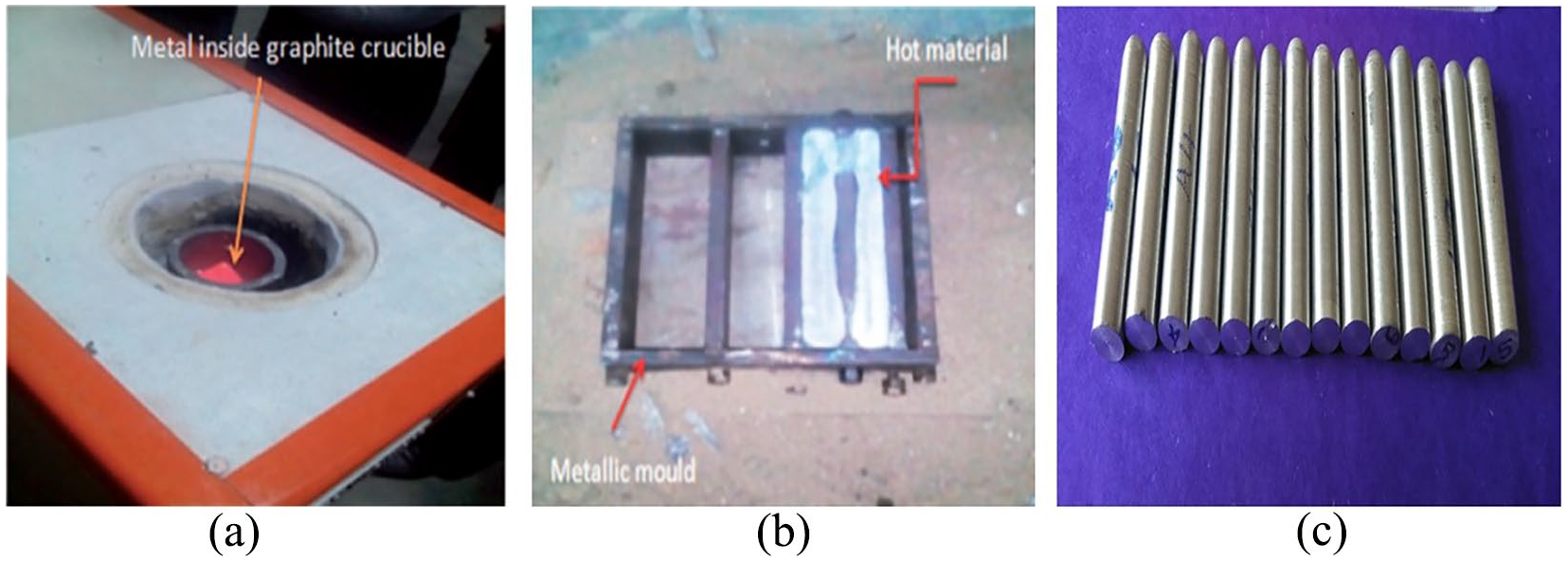
(a) Liquid boiling molten metal inside crucible, (b) liquid metal after pouring in the metallic mould and (c) prepared specimen samples.
SEM analysis of AZ31B/WC composite structures
The alloy and reinforcing peaks in the WC/AZ31B composites were immediately discernible using “XRD analysis,” as shown in Figure 3. After that, “SEM analysis” with a “JEOL JSM 5800 microscope” was performed to examine the microstructural changes caused by the inclusion of WC in Mg matrix composites. SEM is used in materials for micro-level defect monitoring and analysis. The three-point flexure test samples were analysed to look for any differences in failure modes. Cross-sectional incisions were performed through the samples’ failing region. Silver paint, also gold-coated, was employed to fix the sample on the holder to avoid charge buildup from the specimen collecting electrons.
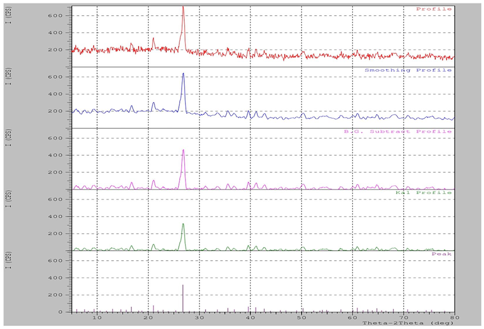
XRD analysis depicting the material’s distribution in the WC/AZ31B composite specimen.
Figure 3 shows how smoothing profile levels can identify the proportion contribution of reinforcement and alloy components in WC/AZ31B composites. Peaks in the composite specimen corresponded to AZ31B alloy contributions, while minor peaks indicated the presence of WC reinforcement. This is consistent with the XRD study, which shows the material distribution in the WC/AZ31B composite specimen. The XRD analyses in Figure 3 were repeated five times to corroborate the magnitudes of the peaks and valleys in the composition of the composite materials. The observations are consistent throughout various analyses.
Figure 4(a) to (c) show SEM microphotographs of the Mg-MMCs. The distribution of tungsten carbide elements under uniform conditions is depicted in Figure 4(a) to (c) using SEM microstructural analysis. Furthermore, it shows a thin, distinct contact between the Mg matrix (AZ31B) and the reinforcement (WC). This design improves the final Mg-MMCs’ load-bearing capacity.
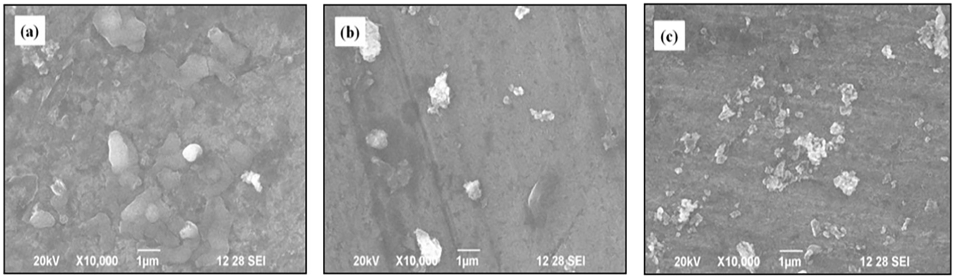
(a) SEM micrographs of AZ31B+5% WC, (b) SEM micrographs of AZ31B+10%WC, (c) SEM micrographs of AZ31B+15% WC composites.
As shown in Figure 4, the addition of WC components into the Mg matrix alloy dramatically modifies the characteristics and microstructure of the WC-particulate-reinforced Mg-MMCs. Metallographic analysis and optical microscopy studies of the composite materials demonstrate a homogeneous distribution of Tungsten Carbide (WC) reinforcing particles in the Mg matrix. The size of the black zone grows as the weight percentage of reinforcement increases. The micrograph shows that inter-particle zones were altered plastically to accommodate the reinforcement. According to EDX analysis, a component of the matrix melted, allowing it to permeate into the calcine dolomite reinforcement and perhaps promote Mg-reinforcement binding. Agglomerates appear to fill the spaces between Mg grains, resulting in a low porosity.
Within this system, localised melting causes deformation in the continuous phase. Image analysis techniques demonstrated that particle pull-out is low, and the calcined dolomite particles do not segregate. When the matrix is moist, it keeps close contact with the reinforcement, resulting in excellent bonding. The composite’s performance is dependent on the resilient inter-phase area, which facilitates the transmission of attributes such as stress from the matrix to the reinforcement.
Analysis of the bone joint structure
Both the hip bone joint and the ball end of the legs were structurally examined. Mesh fitting with consecutive mesh size levels was performed on the completed hip bone joint. Over the complex region of the hip joint bones, an irregular mesh was produced. The bone model was created using Creo’s Solid Modeller Pro. In accordance with the coordinate system, the inclined bone structure was placed using Origin and Mate. Figure 5(a) shows how to make a uniformly distributed mesh Figure 5(b). The sharp-ended ball joint and the bone’s supporting structure are inextricably linked. The mesh region’s convective shape exhibits increasing deformation and tension.
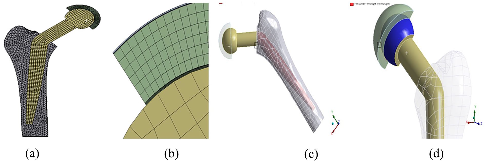
(a and b) Consecutive mesh generation of Assembled hip bone and the Ball joint (c and d) Frictional contact of elements by multiple to multiple option.
Following the bone structure design depicted in Figure 5(a) to (d), a solid mesh with 15,918 elements and 4039 nodes was created. The mesh matrices that followed adequately covered the unevenly curved spline area. The frictionless body element at the joint, the ball, demonstrated good friction resistance. It helps to keep the leg bone area stable and may readily make touch with the bottom leg bone structure. The rolling contact friction of the ball joint, as shown in Figure 5(c), imposes frictional resistance and inclined forces on the bone structure Figure 5(d). The boundary conditions were applied in that ball joint curved region of the bone assembly with the displacement has been arrested in all direction indicated with the x and y components. The completely meshed parts of the ball joint and bond of the hip structure are used to analyse stresses and deformations. All in all, the analysis of the ball joint and its supporting structural components was conducted under diverse loading conditions. Boundary conditions were imposed on the curved section of the ball joint to restrict displacement in all directions (x and y components), hence ensuring stability as well as avoiding undesirable motions throughout the simulation. The selection of these boundary conditions was motivated by the desire to mimic/replicate the physiological restrictions of the hip joint along with offer a comprehensive analysis of the resulting stresses and deformations.
The mesh was produced with meticulous consideration for detail, employing a series of mesh size levels in order to attain a precise fit over the irregularly curved spline region. The uneven mesh was specifically engineered to efficiently encompass the various intricacies of the bone joint structure. The selection for elements throughout the study was conducted with meticulous deliberation in order to effectively capture/record the response of the materials across distinct conditions of loading. The simulation incorporated frictionless body elements at the joint, consequently assuring the presence of real frictional resistance, specifically in the region of the ball joint. The utilisation of this approach enabled a comprehensive analysis of all the mechanical characteristics and interacts occurring throughout the joint.
Therefore, the FEM study employed sophisticated simulation software, such as ANSYS, to predict the patterns of stress distribution and deformations inside the model of the hip joint. The investigation encompassed a study of several forces exerted on the ball joint, encompassing tangential forces (Fx and Fy) as well as resultant forces (Fr). The application for von Mises stress analysis was applied in order to make predictions regarding the probability of failure inside the bone structure. This study employed a methodology to evaluate the distribution of stresses in certain regions, with a specific focus on discovering areas characterised by high levels of longitudinal stress. This comprehensive stress analysis conducted in this research yielded significant insights into the structural integrity of the bone joint when subjected to multiple loading conditions. These findings have contributed to a more profound insight of the mechanical behaviour exhibited by the joint.
Results and discussions
Hardness of the AZ31B/WC composites
This section discusses the importance of the hardness test and provides an analysis of composite hardness. Under a stress condition ranging from 1 to 100 Kgf, the Vickers hardness test involves indenting the test material with a diamond indenter with a square base generating a right pyramid with an angle of 136 degrees between opposed faces. For 10 to 15 s, the overall load is applied to the material. Two diagonals are left as indentations on the surface after unloading. The sloped surface area of the indentation is then measured and estimated on a regular basis using a microscope. The Vickers hardness is calculated by dividing the load in Kgf by the area of the indentation in square millimetre. As cumulative error, the average values of the difference between consecutive and previous hardness, tensile, yield, and flexural strength are confirmed.
The Vickers micro-hardness of AZ31B/WC Mg-MMCs is shown in Figure 6. Specifically, the hardness of AZ31B/15 wt. percent WC MMCs is 76 HV, representing a 31.95% increase over the AZ31B matrix material. This increase in hardness is due to the homogeneous dispersion of WC particles inside the Mg matrix. Furthermore, the higher resistance to plastic deformation is responsible for the improved micro-hardness seen in MMCs containing WC particles.
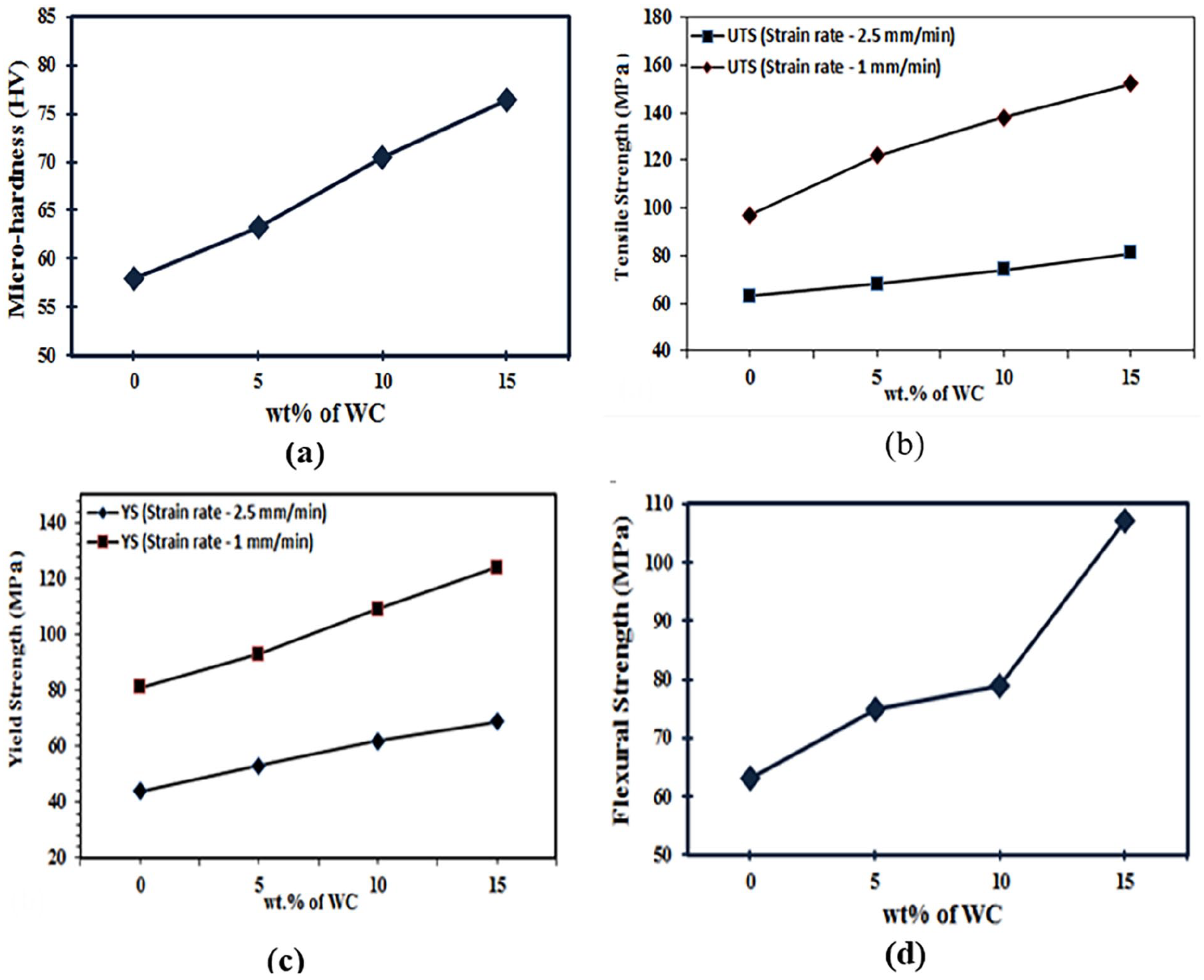
Influence of WC particles on (a) Vickers’s micro hardness of MMCs, (b) tensile strength of MMCs, (c) yield strength of MMCs, and (d) flexural Strength of MMCs.
Tensile and yield strength of the AZ31B/WC composites
Tensile and yield strength tests are performed to evaluate the composites’ performance, analysing the materials’ behaviour under various loading circumstances. A tensile test, commonly known as tensile strength, determines a material’s capacity to endure axial loading without breaking. Continuous forces are applied under each end of the material in an equal and opposing direction, resulting in elongation and diameter reduction. The tensile test analyses many material qualities such as % decrease of area, elongation, lower yield strength, upper yield strength, proof strength, and tensile properties. Figure 6(b) and (c) show the yield and tensile strengths of Mg-MMCs, respectively.
The tensile and yield strength rise noticeably with the addition of WC components, well exceeding the strength of the unreinforced Mg matrix alloy. Figure 6(a) to (d) show that the strength of the composites improves when the strain rate is reduced to 1 mm/min from 2.5 mm/min. At a strain rate of 1 mm/min, the tensile strength of AZ31B/15 wt.% WC composites achieves its maximum. The integration of WC components in Mg-MMCs adds to the improvement in tensile and yield strength by acting as a displacement barrier. The enhanced dislocation caused by the temperature coefficient mismatch improves the tensile and yield strength of MMCs much more.
The graph’s vertical axis shows strain and load values, while the secondary axis depicts stress and deformation values. Testing pure alloys and composites with WC particle reinforcement indicates increased deformation and strain values. As indicated by the considerable deformation and strain levels recorded during tensile testing, this is indicative of ductile fracture. In its pure form, the AZ31B alloy has soft ductile properties and struggles to resist significant load factors. The Zn component of the AZ31B alloy provides self-damping soft ductile characteristics. The stress-strain curve can be illustrated by observing the tensile test limits from elastic deformation to plastic deformation. This stress-strain curve depicts each incremental step of tensile elongation of the specimen sample in the UTM test for the relevant weights.
The yielding point rapidly increases, as shown in Figure 7(a) and (b). Similarly, combining WC in various percentages with pure AZ31B alloy material – 5%, 10% and 15% – results in improved and more stable displacements and strain rates at different yielding locations under the same load condition, as illustrated in Figure 7(c) to (h). Reduced deformations and strain can be achieved by combining tungsten carbides with 0.1% silicon alloying components. For the same load values, all specimens exhibited homogenous stress. The results of the tests show a considerable improvement in the “failure strain” of “AZ31B composites,” with the “strain” increasing in tandem with a rise in the “percentage of WC” in the “composites.” The “homogeneous dispersion” of “reinforcements,” “grain refinement,” and “precipitation” of “fine secondary phases” are all key factors to the increase in “failure strain” of composites. The “grain refinement” of materials with a “HCP structure” improves “ductility.”
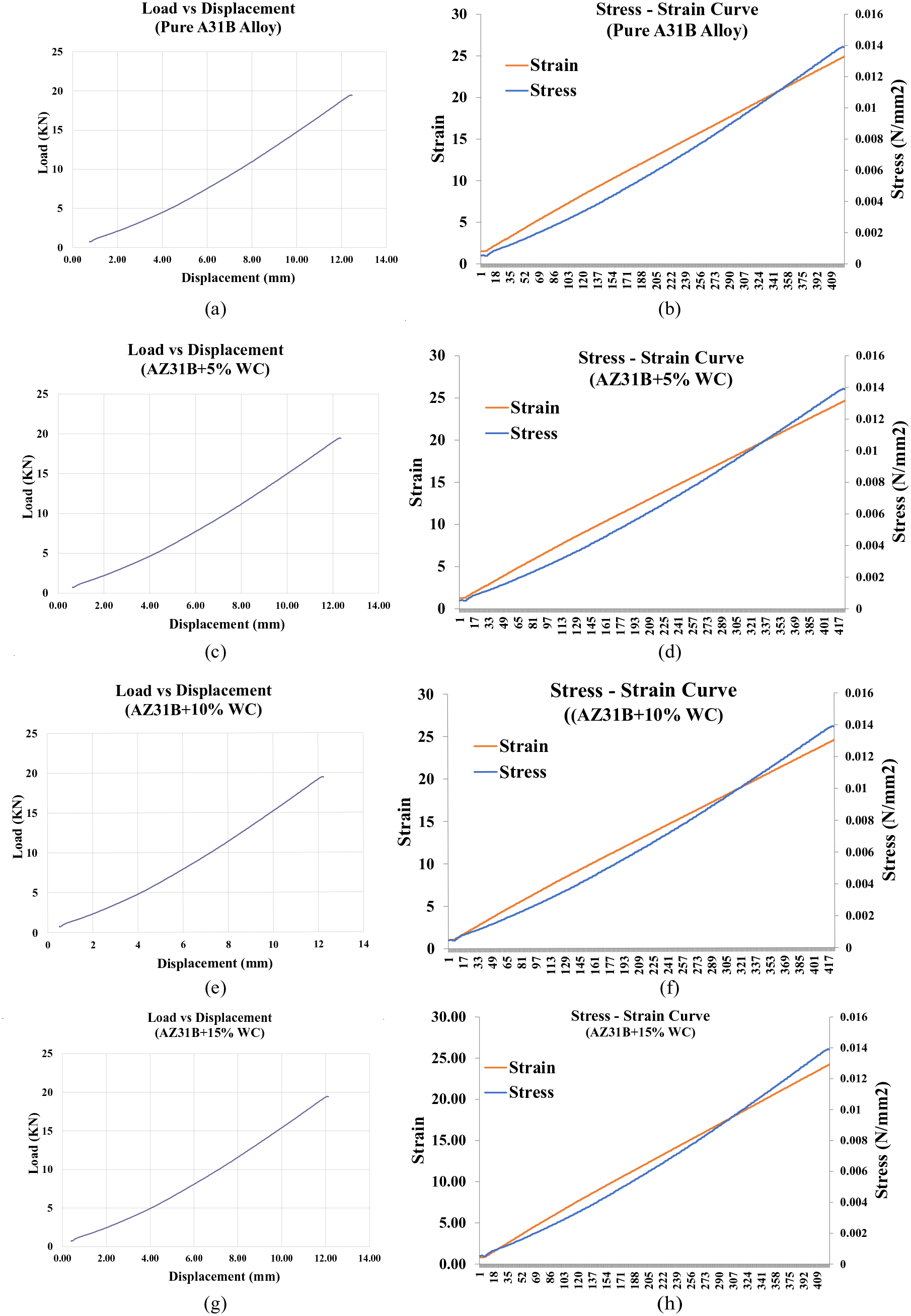
(a–e) “Load versus displacement” curves for (a) “Pure AZ31B alloy”; (c) “AZ31B+5% WC composites”; (e) “AZ31B+10% WC composites”; and (g) “AZ31B+15% WC composites.” “Stress-Strain” curves for (b). “Pure AZ31B alloy”; (d) “AZ31B+5% WC composites”; (f) “AZ31B+10% WC composites”; and (h) “AZ31B+15% WC composites.”
The hexagonally closed pack (HCP) structure of the WC-Mg-based composite improves toughness and ductility. However, an excessive amount of WC may cause the composite to become brittle. To mitigate this, the Mg alloy covers 80%–90% of the alloy element, serving as the dominating material in the matrix reinforcements. As a result, the composite is mostly ductile nature.
The incorporation of tungsten carbide (WC) reinforcing particles in magnesium-based composites plays a pivotal role in enhancing their mechanical properties and influencing fracture surfaces. WC, known for its exceptional hardness and strength, reinforces the magnesium matrix, resulting in increased composite strength and hardness. This reinforcement mechanism restricts plastic deformation and contributes to improved tensile and yield properties. Furthermore, when analysing fracture surfaces, the presence of WC promotes a more controlled failure mode, with finer, more uniform fracture patterns. The combination of increased strength and controlled fracture behaviour makes Mg-WC composites promising materials for applications requiring high mechanical performance and reliability.33 –36
Tensile fracture morphology
The tensile fracture morphology seen in the AZ31B/WC composites is shown in Figure 8. Figure 8(a) shows the fracture morphology of the AZ31B matrix alloy, which exhibits dimples that are evenly dispersed and greater in size. This finding unmistakably points to a ductile fracture mode. Figure 8(a) to (d) show that the amount of dimples significantly decreases with the addition of WC particles. The hard WC particles’ ability to refine grains is responsible for this decrease. The mode of failure shifts from ductile to coupled brittle and ductile due to the presence of WC particles in the matrix alloy. Numerous flat patches can be seen on the fracture surface of AZ31B/WC composites, which suggests a significant amount of brittle fracture and a modest amount of ductile fracture. A significant amount of fragmented WC particles is present on the rupture surface, as seen in Figure 8(d), resulting in improved interfacial adhesion between the matrix and the reinforcement.
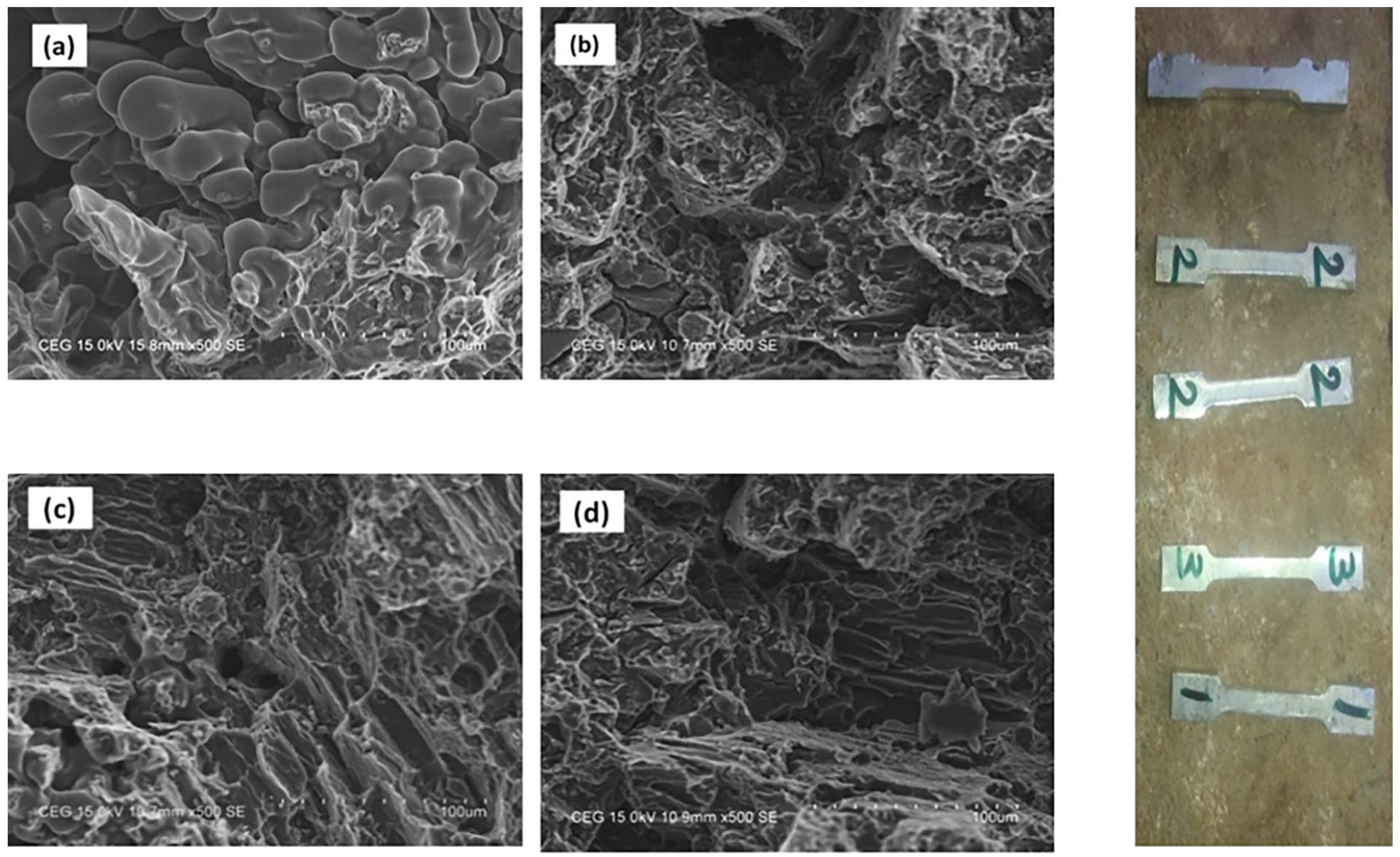
Tensile fracture surface SEM images of AZ31B/WC composites containing (a) 0 wt.% of WC, (b) 5 wt.% of WC, (c) 10 wt.% of WC and (d) 15 wt. % of WC.
Figure 6(d) shows that the weight percentage of WC causes an increase in the flexural strength of AZ31B/WC composites. This characteristic is ascribed to the stir casting technique’s facilitation of the uniform distribution, sturdy interface, and mechanical interlocking of WC particles within the Mg matrix. The consolidated samples are improved by the addition of 15% mass fraction of WC particles, producing samples with greater FS than the typical AZ31B matrix alloy. A mix-suit of thermal coefficients that enhance dislocation is linked to the development of FS in MMCs. The fracture surface is filled with magnesium alloy components as seen by the chipped look in Figure 8(d), and the dispersion of WC particles inside the flaky area helps to effectively strengthen the grain boundary. The finished specimens have gone through a tempering procedure based on hardening concepts.
Furthermore, weight is unintentionally transferred from the WC component to the Mg alloy as a result of the tiny interaction between the magnesium AZ31B and the WC reinforcement. As a result, the composite’s yield strength and tensile strength are improved with a 15-weight percentage increase in tungsten carbide content.
In comparison with the outcomes reported from the prior literary works, the study utilised a modified approach referred to as FSVP, which is a modification of FSP, for the purpose of developing composite surface layers on the AZ91 magnesium alloy. 34 The particles employed in this method were nano-sized SiC powder particles. The research investigated the implications of both FSP and FSVP on the microstructure as well as the mechanical characteristics of the treated specimens. Furthermore, the research explored the impact of the rotational and traverse speeds for the tool on the mechanical characteristics of specimens that undergo processing employing the FS and FSV techniques. 34 The findings indicated that, in contrast with FSP, FSVP led to the formation of smaller grains in the stir zone and a more even uniformly distribution of SiC particles throughout the microstructure. 34 A number of significant discoveries were obtained in this study. Firstly, it was discovered that there is a direct relationship among the efficiency of FSVP and the enhancement of mechanical characteristics. Specifically, as the vibration frequency rises, both the efficiency of FSVP and the enhancement of mechanical characteristics also escalate. Furthermore, the integration of SiC powder particles into the microstructure of specimens developed via the FS and FSV techniques significantly enhanced their strength and ductility. The reinforcing particles played a crucial role, particularly their efficiency rising as their uniform distribution enhanced. 34 Furthermore, it was noticed that the grain size within the stir zone exhibited a rise as the rotational speed raised whereas a reduction was noted with a reduction in traversal speed. 34 It is worth noting that the influence of rotational speed on changes in grain size during FSP and FSVP is more significant compared to the effect of traverse speed. The substantial material deformation occurring in the stir zone during FSP and FSVP not only induces notable dynamic recrystallisation, leading to the formation of finer grains, nevertheless plays a role in ensuring the even dispersion of SiC powder particles, therefore mitigating their tendency to form clustering. 34 In short, the findings of the study revealed that specimens subjected to FSV processing had a finer grain structure in the stir zone when compared to specimens treated using FS. 34 In addition, the specimens in the former grouping displayed a more uniform distribution of SiC particles compared to the specimens in the latter group. The observed difference in outcomes can be related to the impact of workpiece vibration during FSVP. This vibration leads to increased material deformation, which in turn enhances dynamic recrystallisation and reduces the clustering of SiC particles. Furthermore, it was observed that with a rise in vibration frequency, there was an associated reduction in the grain size of the stir zone, along with an enhancement in the uniformity of SiC particle distribution. On the other hand, a rise in the rotational velocity of the tool exhibited a positive correlation with the growth of the grains inside the stir zone, while concurrently leading to a reduction in the mechanical characteristics of the processed specimens. 34
Another study emphasises the investigation of a modified version of FSP, referred to as FSVP, which is utilised for the purpose of generating a surface composite on the AZ91 magnesium alloy. 35 Contrary to traditional techniques, the FSVP approach involves the application of workpiece vibration in a direction that is perpendicular to the processing direction. The outcomes demonstrated a significant enhancement in the even distribution of SiC particles throughout the microstructure, which stands in striking contrast with the findings of FSP. It is worth mentioning that the size of the matrix grains in the samples processed using FSV was measured to be (26.43 ± 2.00) μm, which is much lesser compared to the matrix grains in the specimens treated using FS alone, which measured (39.43 ± 2.00) μm. The noticed enhancement in refinement can be ascribed to the raised plastic strain that results from the vibration of the workpiece during the process of FSVP. This enhanced plastic strain promotes dynamic recrystallisation, leading to the development of finer grains. 35 Furthermore, the study explored the mechanical characteristics of the treated specimens. 35 The specimens treated with FSV exhibited a higher ultimate tensile strength (UTS) of 361.82 MPa compared to the FS-processed counterparts, which had a reported UTS of 324.97 MPa. 35 The plastic strain experienced during the process of FSVP, which is caused by the application of workpiece vibration, had a key role in promoting dynamic recrystallisation. This, in turn, facilitated the formation of smaller grain sizes. The observed phenomena had a beneficial impact on both the elongation and formability index of the samples treated using FSV. Specifically, the elongation raised by 16.88%, while the formability index reached 6107.52 MPa·%. On the other hand, the samples treated utilising the FS method exhibited reduced values for both parameters, with an elongation of 15.24% and a formability index of 4952.54 MPa·%. Additionally, the study revealed that the impacts of FSVP became more pronounced with higher vibration frequencies, hence highlighting the considerable influence of this procedure on the mechanical characteristics. 35 The investigation did not cease at that point; the study thoroughly examined the impact of the tool’s traverse speed and the workpiece’s vibration frequency on the microstructure and diverse characteristics of the developed composites. 35 The findings provided a distinct representation: the mechanical characteristics of the FSV-processed samples exhibited superior performance compared to the FS-processed samples. The inclusion of vibrational component in the FSVP resulted in significant material deformation, exceeding the level attained by FSP. The noticed enhancement in material deformation exhibited a clear correlation with dynamic recrystallisation, hence facilitating the development of smaller grain sizes. It is worth mentioning that the higher material deformation noticed during the process of FSVP resulted in a more homogeneous dispersion of SiC particles inside the microstructure. The outcomes of the study indicated that raising the vibration frequency and traverse speed of the welding tool resulted in a reduction in the grain size of the stir zone for materials treated using FSV, as well as an enhancement in the uniformity of particle distribution. The comprehensive research demonstrates that the FSVP method is a viable and easily implementable approach in numerous industries, in contrary with the traditional FSP technique. 35
Tribological behavior of theAZ31B/WC composites
The test rig was used to do a number of tests to assess the tribological capabilities of composite materials. These tests included a wear loss test, a revolution test, a loading test, a dry sliding test, a vibration test, a test for surface roughness, and a test for loading. The findings of these tests have been made public. To determine whether surface engineering technique permits further investigation and to identify the treatment circumstances under which enhanced wear resistance is attained, as demonstrated by laboratory tests, tiny samples were initially tested under simulated settings. The dry sliding wear parameters of composites with 0%, 5%, 10%, and 15% WC reinforcement are shown in Table 3. Additionally, it details the wear loss seen in both Mg-MMCs and the AZ31B Mg matrix alloy, illustrating how load and WC % affect these tribological parameters.
Observations of mechanical properties on AZ31B/WC composites.
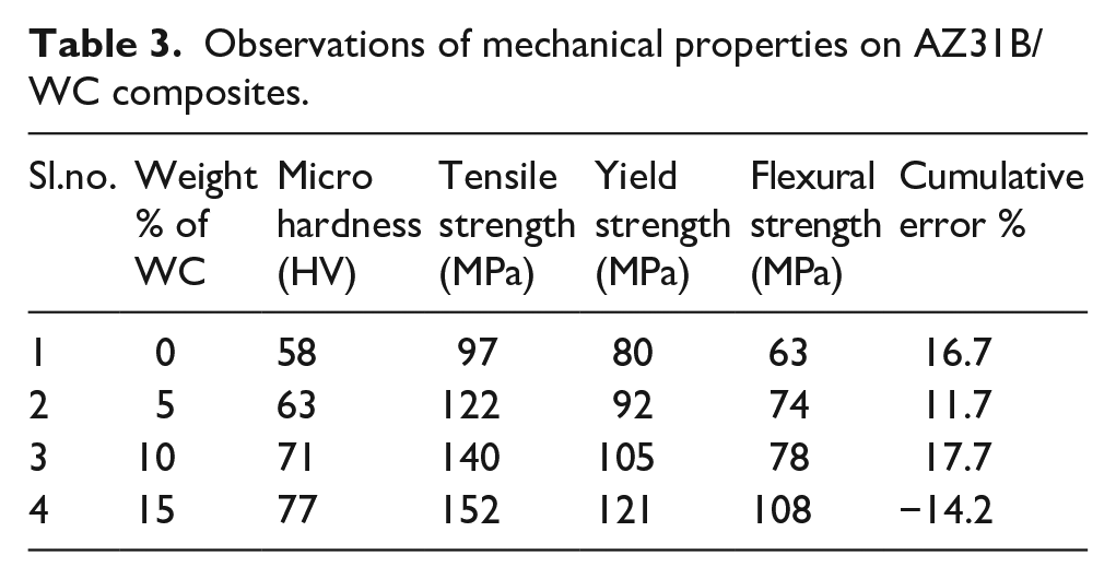
Figure 9(a) to (d) show SEM images of worn surfaces for three different Mg and WC alloy combinations. All base alloys and composites show a particular type of mechanically mixed tribolayer on the wear surface. These zones’ SEM analyses reveal an abundance of oxygen, which suggests that these layers are made up of oxidation products dispersed across the surface. As a result, the manufactured materials’ tribological characteristics significantly improve. With increasing load and speed, this particular layer helps composites wear with rather minor variations.
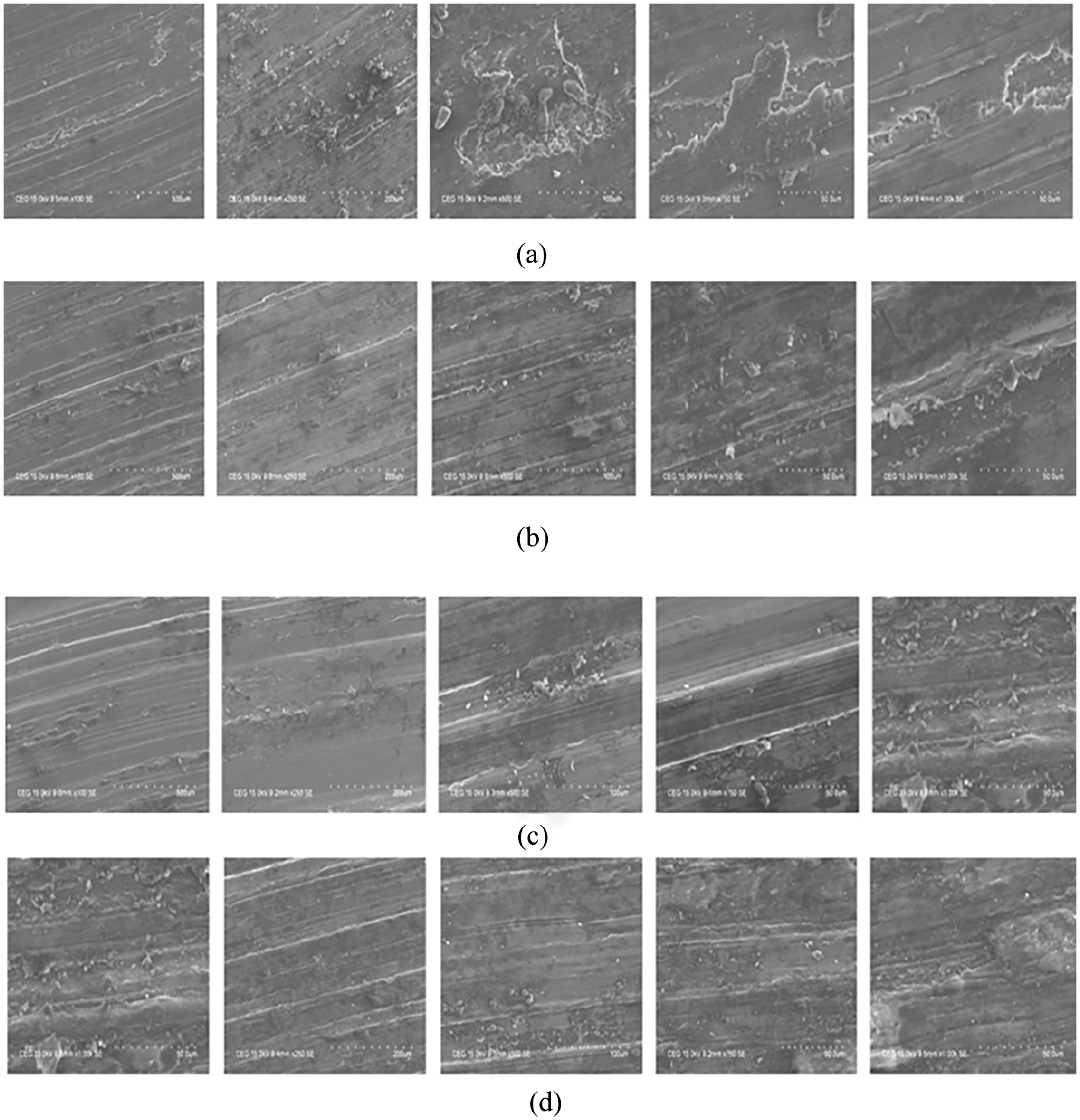
(a) SEM micrographs of AZ31B alloy, (b) sample SEM micrographs of AZ31B+5wt% WC, (c) sample SEM micrographs of AZ31B+10wt%WC and (d) sample SEM micrographs of AZ31B+15w.
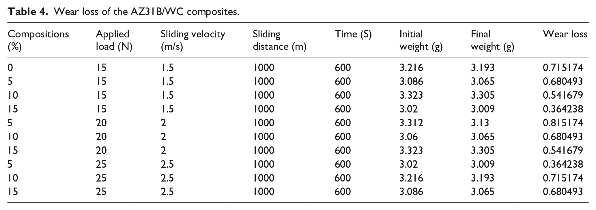
According to the investigation, tungsten carbide particle concentration increases while wear loss decreases. Under constant loads, slide speeds, and slide distances, Table 4 shows a continuous reduction in wear mass loss as a function of WC reinforcement content. The wear data clearly shows that wear loss decreases as WC particle content increases. This behaviour can be linked to the Mg matrix and WC reinforcement’s improved hardness and strong mechanical bonding in Mg-MMCs, especially those with a high weight proportion of WC particles.
Wear loss of the AZ31B/WC composites.
Surface morphology of the worn out AZ31B/WC composites
Figure 9(a) to (d) show SEM micrographs of materials’ worn surfaces, including AZ31B/WC composites and AZ31B. Figure 9(a) to (d) depicts the AZ31B alloy’s worn surface, which is distinguished by a sizable amount of plastic material flow, which exhibits a pattern of parallel grooves but no indication of plastic flow. Hard WC particles, which are thought to naturally be loose and non-adherent to the matrix, are added to the magnesium matrix to increase its hardness.
The worn surfaces of the pure alloy form of AZ31B are shown in Figure 9(a). Several locations in this picture show projected surface faults that are related to the alloy composition and its unevenness. However, there is a considerable decrease in the observed faults on the worn surfaces with the addition of reinforcements, as shown in Figure 9(b) to (d). SEM micrographs of the fracture surfaces shown in Figure 9(a) to (d) allow for a thorough study of this data. The MMC using Mg and WC reinforcement demonstrates a strength two times larger in magnitude than typical metal matrix composites, much like the bulk metallic composite. The presence of WC particles as reinforcements is responsible for this result. Strong particle bonding, made possible by the reinforcement particles, points to improved sintering efficiency as another cause. Additionally, as seen in SEM micrographs, the uneven forms of raw material particles aid in better powder compaction and a more successfully sintered structure.
When comparing outcomes acquired from prior scholarly studies, the utilisation of magnesium alloys in diverse applications, namely in ground and air transportation, requires meticulous welding and joining methods. 36 The precise management of welding operations is necessary due to the distinctive physical characteristics demonstrated by magnesium. FSW, a technique noted for its solid-state characteristics, serves to reduce the concentration of defects. The specimens of AZ31 magnesium alloy were subjected to FSW, whereby SiC powder particles were incorporated into the nugget zone. The process of integration in this study entailed the agitation of pre-positioned SiC particles within the weld. The attainment of appropriate rotation and translation speeds played a pivotal role in ensuring the formation of a structurally stable weld region and even uniformly dispersion of SiC particles. Significant enhancements were observed when comparing the microstructures and mechanical characteristics of AZ31 specimens that undergo FS-welded with and without pre-placed SiC particles. The inclusion of SiC particles led to a reduction in grain size, consequently causing a rise in both strength and formability index. 36 All in all, the study examined hybrid welding and processing methods employed for AZ31 magnesium alloys. 36 SiC particles were purposefully incorporated into the weld zone prior to FSW, enabling a systematic investigation of the resulting microstructures and mechanical characteristics. The outcomes of this research were carefully compared and contrasted with the findings obtained from samples welded utilising the FS technique. When subjected to suitable welding and processing conditions, the SiC particles exhibited a homogeneous dispersion, together with a minimal grain size and interparticle spacing. The inclusion of SiC particles during the stirring process significantly raised the ductility, strength, and formability index of the treated sample compared to the FS-welded counterpart that did not have SiC infusion. 36 The study reveals the significant contribution of SiC particles in augmenting the mechanical characteristics of welds made from AZ31 magnesium alloy. 36 The application of FSW technique, incorporating SiC particles inside the weld region, has been identified as a notable method that yields superior outcomes. A thorough incorporation of various elements not only strengthened the weld’s structural integrity nevertheless substantially enhanced its capacity to be formability, and its overall strength. Therefore, this study highlights the real-world significance of optimising welding parameters and integrating reinforcing particles such as SiC to enhance the mechanical characteristics of magnesium alloy welds. This, in turn, facilitates their wider and more efficient utilisation across different sectors. 36
Another related study, where the FSP technique is notable for its ability to modify the characteristics of metals by the use of concentrated plastic deformation, based upon the fundamental principles of FSW. 37 Within the scope of this investigation, significant alterations were observed in the mechanical characteristics of AZ91 magnesium alloy as a result of FSP. In this study, surface composites were fabricated using SiC, and Al2O3 nanoparticles. 37 The comprehensive examination encompassed the quantification of both yield and tensile strengths, in addition to the determination of hardness values for the specimens. The outcomes exhibited a notable change in grain size as a result of friction stir processing, leading to noticeable enhancements in mechanical characteristics. 37 Additionally, the study demonstrated that the use of SiC particles resulted in more significant enhancements when compared to Al2O3 particles, hence making a notable contribution to the improvement of properties. The research findings indicate that the uniform distribution of particles resulted in a significant decrease in grain sizes, namely to 3 μm. The observed phenomenon of an equitable dispersion of properties was discovered to be positively associated with a substantial rise in both strengths, reaching a value of 390 MPa, and formability index, which escalated to 6500 MPa. 37 The aforementioned findings highlight the crucial relevance of FSP and the strategic utilisation of reinforcing particles in modifying the mechanical characteristics of AZ91 magnesium alloy. These findings emphasise the vital role of particle dispersion in optimising both the strength and formability of the alloy. 37
Comparison analysis of actual and predicted performance of mechanical characteristics
Figures 10 to 12 have demonstrated the variance in actual and predicted performance for micro hardness, tensile strength, and yield strength, respectively. The comparison is performed in four distinct scenarios: no WC, WC of 5%, 10%, and 15%, The comparison chart displays the relationship between actual and expected numbers.
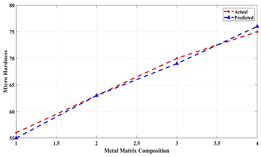
Comparison of Micro Hardness.
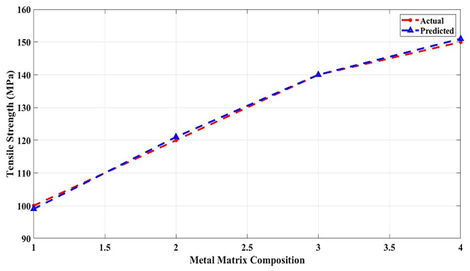
Comparison of Tensile Strength.
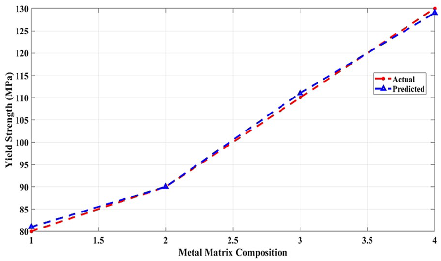
Comparison of Yield Strength.
The micro-hardness of the MMC is examined in Figure 10 for three different examples of actual and anticipated values. We can see from the line chart that one of the four occurrences is precisely the same as the others, while the other three yield less than one unit variation.
Figure 11 is a tensile strength comparison chart displaying the actual and predicted tensile strength of four MMC combinations. One combination provides the same outcome in two of the four options. The other combinations produced similar results with slight changes. Figure 12 depicts the yield strength of real and predicted MMC. The MMC in four different combinations is compared in the figure; in the first case, the Mg is tested without the WC and in the other three cases, the WC is added in percentages of 5%, 10%, and 15%. The comparison clearly shows how closely matched the actual and predicted test results are. According to the test findings, the hardness and strength of MMC may be enhanced by combining an appropriate proportion of WC with Mg in the MMC production. The optimal quantity to make the best MMC utilising Mg and WC was determined by simulation using the LCO algorithm.
The performance of the simulation models is evaluated and explained using FEM analysis. The final mixture is then experimentally simulated and hardness and strength tested. After then, the simulation and experimental results are compared for resemblance and variation. The comparison graphs show that the projected result was correct. As a result, LCO became a viable technique for MMC simulation. The main properties of the MMC are low thermal expansion coefficient, good wear resistance, improved specific strength, and lightweight based on this, the materials are one of the main advanced materials in the current industry applications. The article has thoroughly explained the MMC fabrication with the use of the stir casting method. To attain the efficient process of fabrication of MMC for improved mechanical properties and low density based on the reinforcement material of WC and stir casting progress which is the successful method.
The stir casting method is a conventional route and cost effective for the manufacture of composite materials. In this study, the investigators have thoroughly discussed the process of the stir casting method for fabricating the Mg/WC composites to meet various applications such as aircraft and automobiles. To assess the given composites, several tests such as micro-hardness, ultimate tensile, flexural, and microstructure characterisation are employed. Based on the analysis, this study has evident the efficiency of the proposed composites. The main objective of the work is for computing the tribological, morphological, structural deformation, and mechanical characteristics of WC particles reinforced with the fabrication of AZ31B composite materials by liquid state process. The WC particles in Mg matrix composites analyse the uniform distribution through the SEM analysis.
Stress predictions and force distribution of bones and joints
The displacements and stress distributions over the hip joint modelling can be predicted based on the distribution of forces as shown in Figure 13.
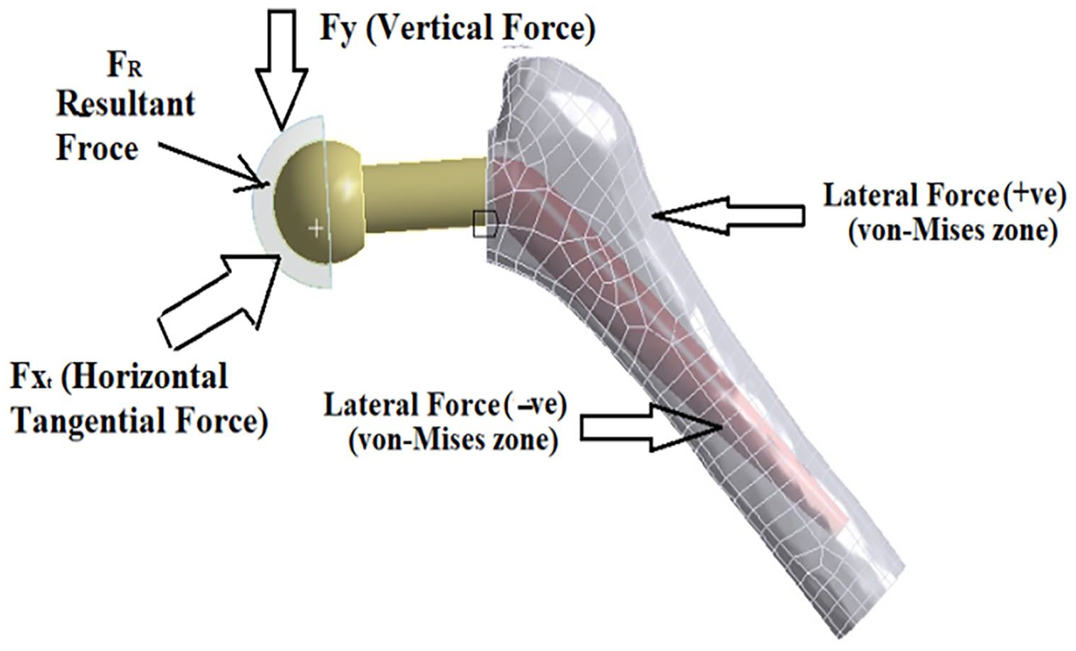
Statements of hip joint force distributions.
According to Figure 14(e) and (f), three forces operate along the hip joint’s ball end, which rotates due to friction inside the pelvic bone area’s conical block. The femur bones, which link to the leg bones, may uniformly transmit half of the total body weight. As a result, the circular ball joint is tangential to the horizontal and vertical forces (Fx and Fy). In response to sudden or continuous body motion, resultant forces (Fr) come into play, offering a well-balanced support mechanism to avoid collisions or fractures among the femur bones. The top and bottom sides of the femur bones may fail or fracture in severe circumstances where body dynamics are unimportant and material selection is poor due to lateral shearing. The von Mises stress, as shown in Figure 14, can be used to predict the likelihood of failure in the lateral structure of this bone joint. The forces acting on the hip joint structure determine the degree of stress, and Figure 14(a) and (b) show the overall deformation during fast walking. At the top of the ball end, there are more noticeable deformations that are gradually spread along the length of the femur bones. The interior bones exhibit similar values. The contact analysis of the hip joint cup and cone simulation is clarified using ANSYS simulations. The structural portion of the bone has been evolved into a solid modeller that explains both its normal state and the effects of rapid movement. These simulation tools provide information on complex material assignments.
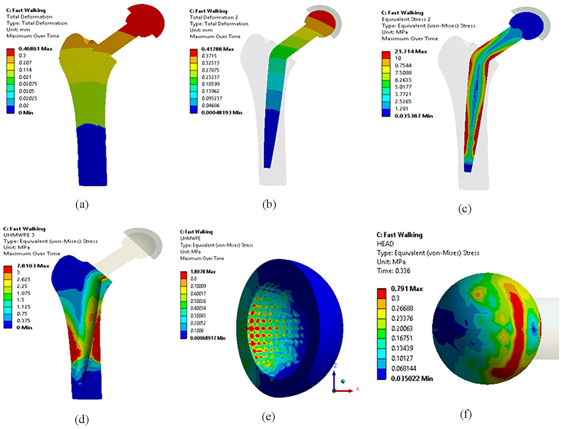
Analysis during the fast walking (a and b) Total deformation levels of leg hip joint bone in ANSYS, (c and d) Linear and Longitudinal von Mises stress analysis of Hip bone joint, (e and f) von Mises stress of frictional area of the inside and outside of ball joint.
The von Mises stress, also known as the failure stress, appears at particular locations within the bone structure, emphasising how intensely longitudinal stress is formed. Stress is spread across the central region of the bone structure as a result of the bending moment that femur bones undergo, as shown in Figure 14(d). Figure 14(c) shows that during rapid leg movement, four places in the smaller leg bone structure experience the greatest von Mises stress, which reaches 21.714 MPa. Similar to the inner bones attached to the ball end, the outside bone structure shown in Figure 14(d) displays stress values of 7.8103 MPa, which is the lowest. The inner frictional surface of the conical ball joint region and the outer semispherical surface of the ball joint are both subjected to optimal stresses of 1.8078 and 0.791 MPa, respectively. The lateral force on the positive side, as shown in Figures 13 and 14, is equivalent to the force acting along the kneel side.
An experimental and numerical examination on a “laminated composite” including “E-glass fibre” and “reinforced polymer (GFRP)” was done together with the corresponding comparative analysis to determine its dynamic response to “low-velocity impact.” 38 Utilising a matrix of Mg (AZ31B) with various quantities of WC reinforcement increases the ability to produce hip and kneel bone structures with strong material suppression while maintaining these structural dynamics under safe loading conditions.39 –41 They have already incorporated Ca, Al, and Zn into the Magnesium (Mg) alloy to transform it into a composite.42 –44 This biomaterial is suited for the hip joint since it has effectively attained the flexural, tensile, and microhardness levels. Minimal wear loss has been observed for the 15% WC-Mg MMC at a sliding velocity of 1.5 m/s along a length of 1000 mm under an applied load range from 15 to 20 N. However, SEM Figure 9(a) to (c) show a number of oscillations that are ascribed to an improbable bonded material structure and incorrect reinforcement distribution.45 –47 Figure 9(d) show distinct grain boundaries and microstructures, which is consistent with findings from other investigations.44 –46 One of the most effective versions of this MMC48 –50 for biological applications is the addition of WC.51 –53 These new composite materials have also been used to increase material strength and structural integrity by utilising stronger compressive and tensile characteristics while reducing brittleness.33,54,55
Conclusions
As part of the study, stir casting was employed to analyse the mechanical, microstructural-morphology, and tribological characteristics of magnesium matrix composites (MMCs) that were strengthened with WC particles. The goal was to improve AZ31B magnesium’s mechanical and tribological properties with WC reinforcement. AZ31B/WC composites attained 76 HRB macro-hardness with 15% WC particles, which is 31.95% harder than basic AZ31B. SEM showed a homogeneous WC particle distribution in the magnesium matrix. Tensile strength peaked at 152 MPa in 15% WC composites, whereas yield strength reached 124 MPa. Wear resistance improved with WC content, with AZ31B-15 wt% WC composites wearing the least. The worn surfaces of AZ31B/WC composites had parallel grooves without plastic flow, while the alloy surface had significant plastic deformation.
i. The introduction summarised magnesium’s features, advantages, and applications. After considering metal matrix composite (MMC) reinforcing materials, WC was chosen. Literature analysis and induction studies helped find the optimal materials for lightweight MMC manufacture.
ii. The MMC, with WC as the reinforcing matrix and Mg as the base metal, was developed. Optimisation using locally convex optimisation (LCO) determined Mg and WC ratios. LCO produced random Mg and WC proportions and suggested 1:0, 0.95:0.05, 0.9:0.1, and 0.85:0.15 based on FEM analysis.
iii. Mg MMC manufacture followed the LCO study’s combinations. Stir casting makes Mg/WC composites. Mg/WC composites were tested for microhardness, yield strength, tensile strength, and SEM microstructure. Results from 0%, 5%, 10%, and 15% were extensively examined.
Hence, the final performance investigation shows that the composite has adequate strength and hardness at 10% WC. Mg/WC properties were assessed using wear loss calculations. Mg/WC composites are used in lightweight biomedical applications. These composites are suited for biomaterial applications because WC material boosts strength in high-strength multidimensional areas.
Footnotes
Acknowledgements
Researchers Supporting Project number (RSPD2024R576), King Saud University, Riyadh, Saudi Arabia.
Author contributions
Conceptualisation, ND, ABHB, GB, NR, SR, SS; methodology, ND, ABHB, GB NR, SR, SS; formal analysis, ND, ABHB, GB, NR, SR, SS; investigation, ND, ABHB, GB, NR, SR, SS; writing – original draft preparation, ND, ABHB, GB, NR, SR, SS; writing – review and editing, SS, GS, FAA, MIK, EAAI; supervision, SS, GS, FAA, MIK, EAAI; project administration, SS, GS, FAA, MIK, EAAI; funding acquisition, SS, FAA, MIK, EAAI. All authors have read and agreed to the published version of the manuscript.
Consent to participate
Not applicable.
Consent to publish
All authors have read and approved this manuscript.
Data availability statement
My manuscript has no associate data
Declaration of conflicting interests
The author(s) declared no potential conflicts of interest with respect to the research, authorship, and/or publication of this article.
Funding
The author(s) disclosed receipt of the following financial support for the research, authorship, and/or publication of this article: Researchers Supporting Project number (RSPD2024R576), King Saud University, Riyadh, Saudi Arabia.
Ethical approval
Not applicable.