
Abstract
Carbon nano/micro-structures used as fillers in metallic lightweight alloy matrix composites are receiving considerable attention in scientific research and industrial applications. Aluminum and magnesium are the most studied light metals used as matrices in metal composites materials, principally for their low density (respectively 2.7 g/cm3 and 1.7 g/cm3) and low melting temperature (around 660 °C for both metals). A good interaction between matrix and fillers is the first step to obtain an increase in bulk properties; furthermore, the manufacturing procedure of the composite is fundamental in terms of quality of fillers dispersion. In this work the influence of surface modifications for three classes of carbon fillers for aluminum and magnesium alloy (AZ63) as matrices is studied. In particular, the selected fillers are short carbon micro fibers (SCMFs), carbon woven fabrics (CWF), and unidirectional yarn carbon fibers (UYFs). The surface modification was carried out by a direct coating of pure nickel on fibers. The electroless pure nickel plating was chosen as the coating technique and the use of hydrazine as reducing agent has prevented the co-deposition of other elements (such as P or B). Scanning electron microscope (SEM) and energy-dispersive X-ray spectroscopy (EDS) analyses were performed to study the effect of surface modifications. The mechanical properties of manufactured composites were evaluated by 4-point flexural tests according to ASTM C1161 (room temperature). Results confirm improved interactions between matrix and fillers, and the specific interaction was studied for any chosen reinforcement.
Introduction
Light alloys are widely used in different industrial sectors that need more performing materials with good mechanical properties and low weight, 1 in particular: automotive, aerospace, 2 energy transportation, and nautical industry. 3 In this field, many companies are in constant search of innovative materials with technical and economical potential for successful competition on the market. Metal matrix composites (MMC) materials represent a satisfactory solution for these needs thanks to the possibility of obtaining lighter materials with improved metals bulk properties (such as electrical and thermal conductivity or mechanical properties). 4
The effects of carbon nanostructures on MMC materials production are increasingly studied by many researchers, and nowadays graphene and carbon nanotubes represent interesting fillers for the production of MMC materials. The production of MMC materials with these types of structures can be achieved with different techniques, for example additive manufacturing, casting, and powder metallurgy, as extensively studied by Saboori et al.5, 6
Despite these advantages, the production of MMC still has some issues—such as poor wettability between carbon and molten metals or chemical reactions during the manufacturing process—that can lead to the formation of some brittle products phases that may reduce physical properties of the composites. 7 Functional coating, obtained by various processes,8, 9, 10 is one of the most promising techniques to protect fibers and to enhance the interaction with the molten matrix. In particular, metallic coating is the best candidate to overcome difficulties due to the production process of composites: in fact, molten metals can easily wet solid metals, and the formation of brittle phases because of chemical reactions is less probable. 11 Metallic coatings are usually deposited by electroless deposition, electro-plating and cementation. 12 Fibers treated by vapor phase deposition like cementation have more defects, which corresponds to decreasing properties of the composites. The electrodeposition requires the use of an external electrical current, which involves a difficult application in the case of fibrous reinforcements since to impose a potential difference at the two extremes of each single fiber is impossible. Electroless approach, for this reason, is the easiest and most efficient process for fibers, but also for any complex geometry. The redox system mainly used in the electroless process involves the formation of a Ni-P alloy (with low phosphorus content between 6 and 10 wt%) as a product of deposition reaction, preventing its use in high temperature processes. A new electroless process of synthesis that uses hydrazine as a reducing agent has already been proposed, 8 preventing the co-precipitation of P inside the Ni matrix.
Carbon fibers (micro- and nano-sized) are usually studied in MMC production because of their physical properties (electrical conductivity in the case of carbon nanotubes3, 13) and their elastic modulus and tensile strength (in the case of microfibers 14 ).
Interactions between nanostructures’ reinforcements and metal matrix can be improved also with two different post-processing techniques, as studied by Saboori et al. 15 In fact, they analyzed the effects of repressing-annealing and hot isostatic pressing (HIP), in a copper-graphene nano-platelets composite production. In their work were displayed improvements in terms of densification, Vickers hardness, and thermal conductivity mainly on samples subjected to HIP post-processing treatments.
The aim of this work is to verify the direct influence of pure Ni coating onto three different carbon structures, short carbon microfibers (SCMFs), carbon woven fabrics (CWFs), and unidirectional yarn carbon micro fibers (UYFs). A new melting-casting procedure was selected to manufacture aluminum- and magnesium-based composites in order to obtain good dispersion of fillers. In fact, a powder metallurgy process allowed us to easily mix metal powder with fillers thanks to their comparable dimensions. Furthermore, directly after the induction melting process, 13 centrifugal casting method was used. This method uses centrifugal force to possibly align fibers in the melted matrix during the melting-casting process.
Materials and methods
Micrograf HT carbon microfibers and woven fabric (text: 180 g/m2, 0–90° orthotropic and balanced) produced by PROCHIMA (Italy) were selected, respectively, as SCMFs and CWF.
Single strands of CWF were used as UYFs to obtain unidirectional sandwich structure composites. Aluminum powder (particles size ≈ 30 µm) and AZ63 shavings were provided by COMETOX (Italy) and used without further purification.
Electroless pure nickel plating was carried out using the method of hydrazine, as described elsewhere. 8 Briefly, nickel chloride and hydrazine were used as, respectively, nickel source and reducing agent. The nickel, before reduction, was complexed by adding lactic acid and disodium ethylenediaminetetraacetate (Na2-EDTA) to avoid a fast and uncontrolled reduction of nickel. The pH was adjusted by adding NaOH solution just before heating the solution. All the chemicals were purchased at SIGMA Aldrich and used without any further purification. Temperature, pH, and stirring were continuously monitored and maintained constant at the value reported in Table 1.
Nickel deposition parameters.
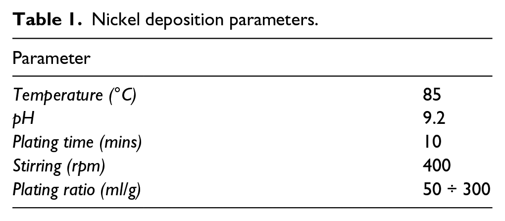
Plating ratio is defined as the quantity of solution per mass of substrate to be plated and it was studied for the values between 50 and 300 ml/g only for the SCMFs. Nickel deposition onto CWFs and UYFs was studied just for 300 ml/g for reasons of size and shape of the substrate. Nickel-coated fibers were recovered from the deposition solution through a filtration vacuum system and dried in an oven at 80 °C for six hours. After drying, the fibers were installed on stubs with conductive cement to perform the SEM microscopy.
Density measurements were carried out in a helium pycnometer mod. AccuPyc II 1340 produced by Micromeritic (Italy). The difference in terms of density before and after deposition allowed evaluation of the quantity of nickel. Surface morphology was studied by SEM analysis with a PHILIPS XL-40 microscope (FEI BV, Eindhoven, The Netherlands) equipped with an EDS system (EDAX Team AMETEK Analysis Division). Another type of SEM (Tescan MIRA3) was used to evaluate the interaction between the metal matrix and Ni-coated fillers, in particular for UYF composites, thanks to the ability to work at high magnification on this equipment.
Aluminum composites with SCMFs (2 %vol) were prepared by mixing the metal powder with SCMFs nickel-coated in a mortar with a comparative quantity of acetone to facilitate the dispersion procedure. The mixture obtained was hot pressed at 200 °C and 6-bar into pellets before the melting process and after the complete evaporation of acetone.
In the case of the magnesium alloy, a good dispersion was obtained by manually mixing fibers with shavings in a mortar. In both cases, composites were obtained by melting and casting with a Neutor Digital F.lli Manfredi (Italy) induction furnace. 16
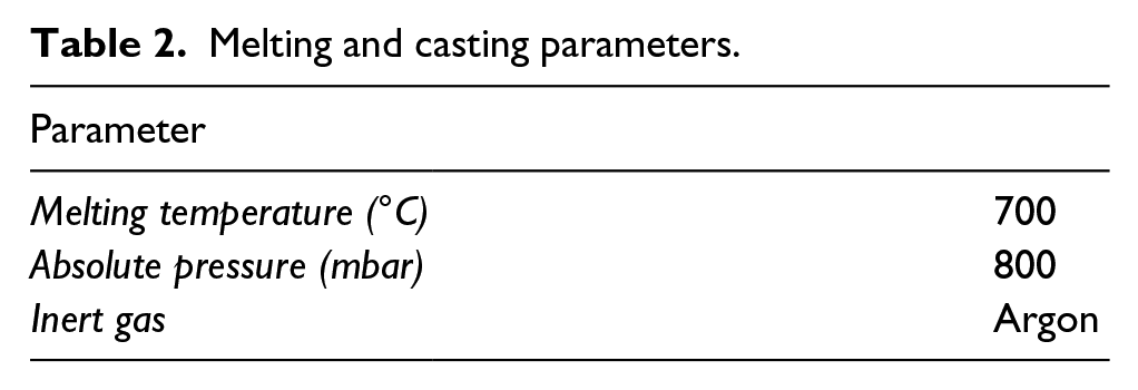
This manufacturing processallows melting under a controlled atmosphere (Ar), without any undesired oxidation (Table 2), and casting with centrifugal force: this approach could, potentially, help the alignment of fibers onto the molten matrix just by considering the fluid (molten metal) drag actions, which could constrain the fibers in a configuration of minimum resistance (Figure 1a). In this case, the possibility of tailoring the density of fibers becomes a key route for the good quality of the composite.
Melting and casting parameters.
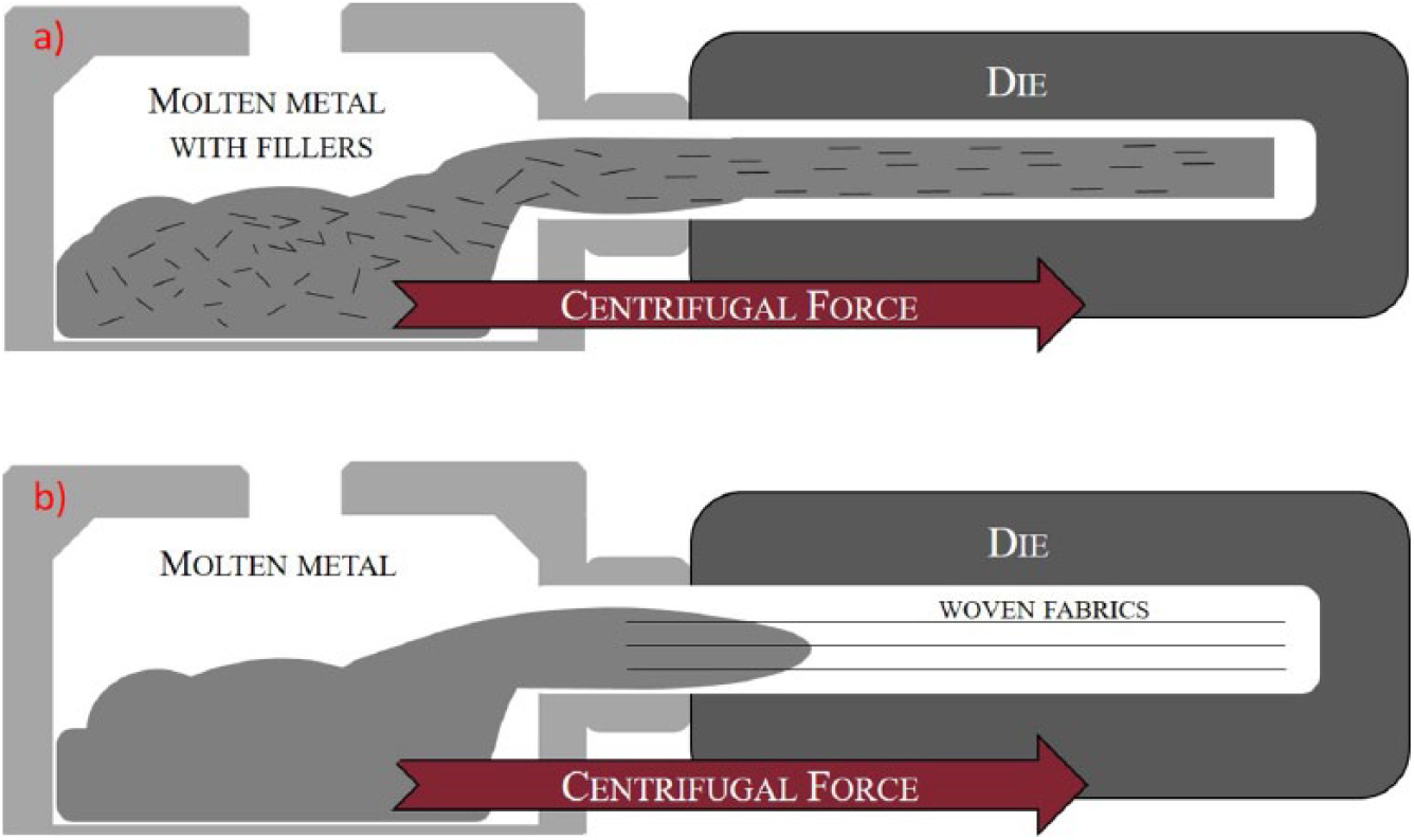
Melting and casting schema of composites with a) SCMFs and b) CWFs and LCFs.
Sandwich-like composite structures with CWF and UYFs were obtained by allocating long fibers directly in the die and by casting the molten metal with the same procedure as for the SCMFs (Figure 1b).
All cast samples for mechanical tests were cut into rods (4 × 3 × 50 mm) and then polished with a silicon carbide (SiC) paper (P600), three samples per type of composite produced were tested. Cast samples prepared for metallographic analysis were cut and polished with SiC papers up to P4000 and then analyzed by SEM microscopy (PHILIPS XL-40).
Density of casted samples was measured by using a ME54 Mettler-Toledo (Italy) analytical balance equipped with the tool for solid density measurements by the Archimedes principle. The composite samples’ experimental density values were compared with theoretical ones calculated according to the rule of mixtures.
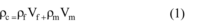
Where ρC is composites density, ρf is fibers density, ρm is matrix density, Vf is volumetric ratio between fibers and composite, and Vm is volumetric ratio between matrix and composite.
Mechanical tests were performed, at room temperature, according to the ASTM C116. Bending tests were performed with a Zwick-Roell Z 2.5 testing machine (Zwick GmbH, Ulm, Germany) equipped with a 3-point-contact extensometer and a silicon carbide fully-articulated flexure device. 17
After bending tests, fracture surfaces were observed with SEM and EDS to evaluate the evolution of composite structure and surface adhesion of nickel coating on fibers.
Results and discussion
Table 3 shows increasing density results for increasing values of plating ratio. As expected, the density values of the coated fibers are always higher than fibers as received, and the case of 300 ml/g plating ratio displays the highest value (5.5 g / cm3) with a thickness of around 1 µm.
Density variation with different plating ratio of Ni deposition.
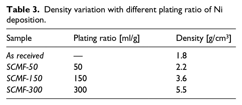
According to the growth mechanism of pure nickel plating, a higher amount of nickel available for reduction does not necessarily imply a thicker coating of nickel. As already explained in other work, 8 in some specific deposition conditions the growth domains may involve the formation of nickel domains that fail to coalesce into a homogeneous and continuous coating.
SEM and EDS analyses (Figure 2), in agreement with this theory, display surface morphology of SCMFs Ni-coated with different plating ratios. Parameters obtained for SCMF-300 were selected as optimal for the Al composite manufacturing, consistent with results obtained from density measurements and superficial morphology analyses.
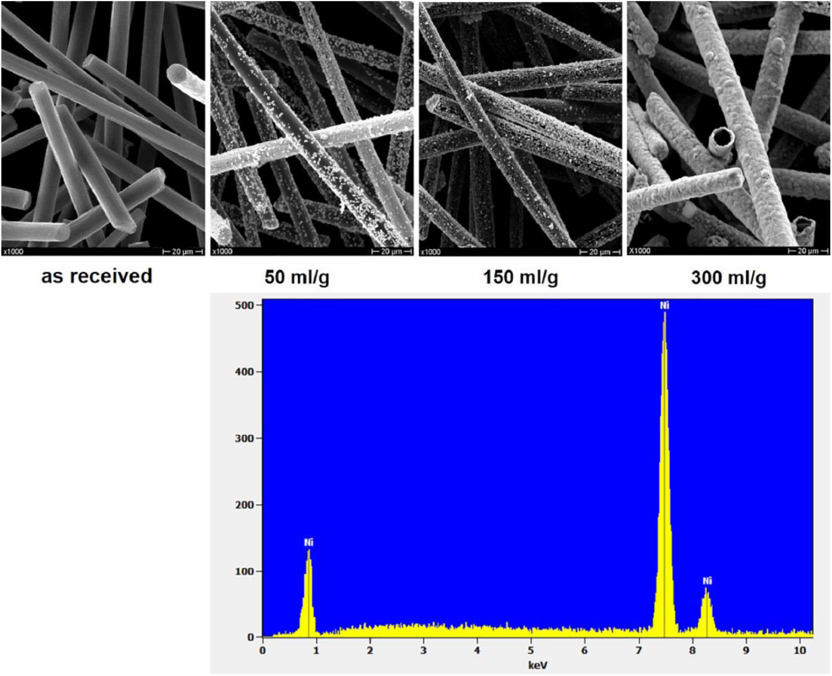
Electroless nickel deposition on SCMFs at different plating ratio.
Parameters obtained for SCMF-150 were selected for magnesium composite manufacturing. Even if the coating is not as homogenous as for SCMF-300, the density of SCMF-150 (3.6 g/cm3) is the best choice to obtain a good dispersion of the filler inside the molten matrix during the centrifugal casting, considering the density of AZ63 alloy (1,8 g/cm3). Theoretical (calculated by the rule of mixtures) and measured densities are shown in Figure 3.
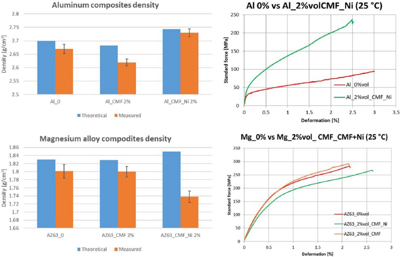
Density and mechanical tests obtained on aluminum and AZ63 composites with SCMFs.
Density analysis seems to reveal that the adoption of Ni-coated carbon micro fibers leads to a reduction of the samples’ porosity and the bending tests, as shown in Figure 3, confirm the expected improvement in terms of mechanical properties. The significant density difference between aluminum and uncoated SCMFs is the cause of fibers floating in the molten metal and leads to a phenomenon of segregation along the casting axis, with a higher concentration of fibers in the terminal part of the cast sample and a large amount of porosity on the surface of the composite. For this reason, the samples obtained from uncoated short fibers were not mechanically tested and the relative data are not reported in Figure 3.
AZ63 composites with Ni-coated and uncoated SCMFs display a different behavior if compared to Al-based composites. Comparison between theoretical and calculated densities reveals that the Ni functional coating promotes the formation of porosity within the composite. Bending tests confirm the results highlighted by density measurement: the larger porosity amount in samples with Ni-coated fibers leads to a worsening of the mechanical properties in terms of yield and flexural strength.
SEM and EDS analyses were carried out both on as-cast and mechanically-tested samples. Results for the Ni-coated SCMFs / Al composites are shown in Figure 4: SEM-EDS analysis reveals the presence of Ni within the Al matrix (Figure 4 a–c), probably due to nickel reaction and diffusion during the casting phase, as already reported in literature.18, 19 At the same time, a residual Ni layer is detectable on the surface of the embedded SCMFs, with a Ni gradient in the Al matrix in the area encircling the fibers, as shown in Figure 4 d–f.
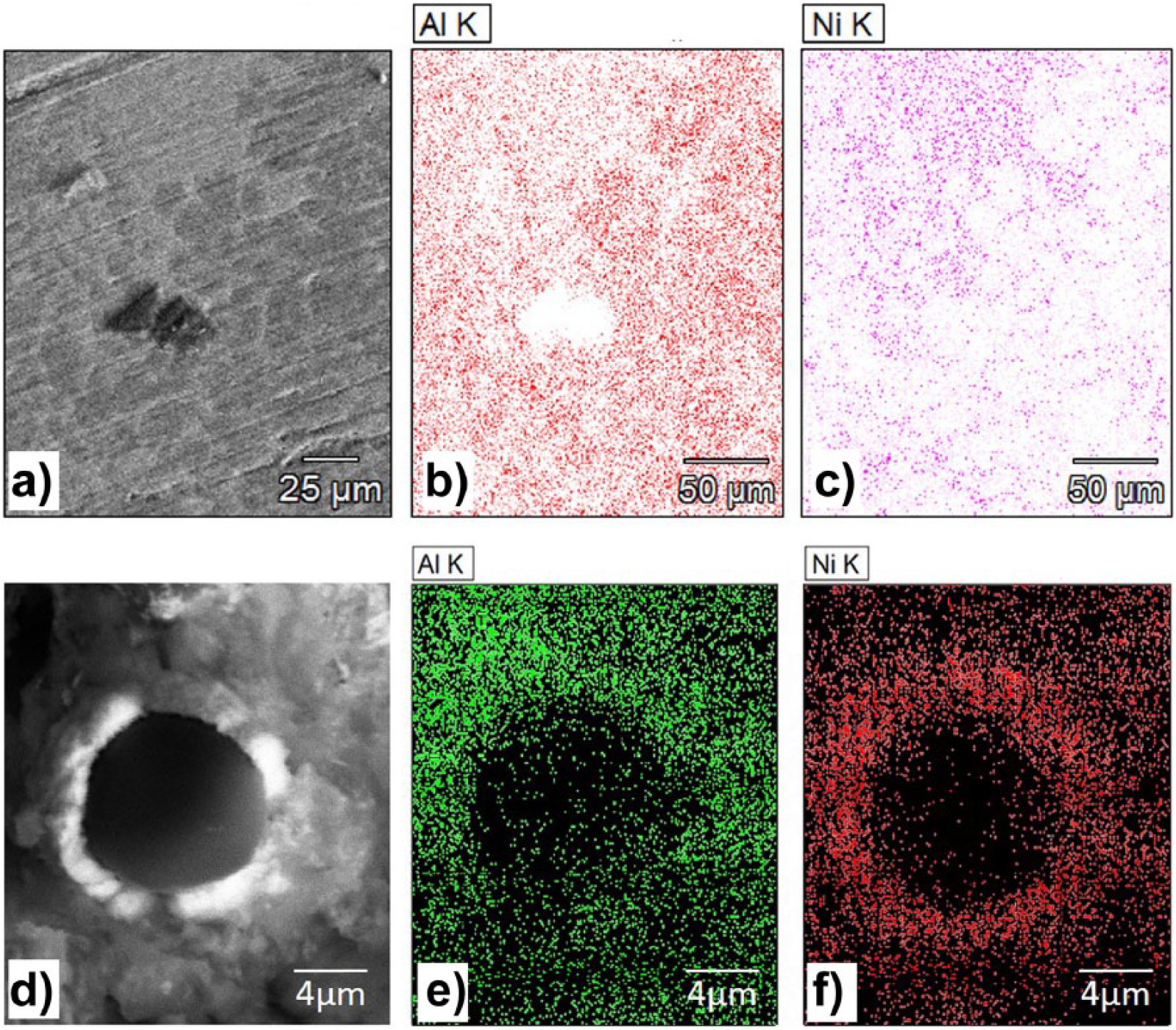
SEM and EDS analysis performed on composites with SCMFs nickel-coated.
The presence of Ni in the Al matrix (solid solution and/or intermetallic phases precipitation) as well as the effectiveness of the Ni-coated fibers reinforcement mechanism could explain the improvement in the mechanical properties highlighted in Figure 3.
Figure 5 confirms the theory of Ni diffusion during the melting process for magnesium-based composites also and explains the results of mechanical tests and density analyses obtained on AZ63 with coated SCMFs. In fact, this figure is only one of all the figures obtained on composites with coated SCMFs, showing fibers that have completely lost Ni coating during the production process, as a consequence, are not wetted by metal matrix.
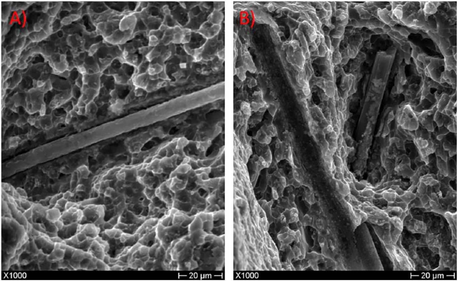
CMFs coated with nickel by electroless in AZ63 alloy matrix.
The sandwich-like approach to composite manufacture was chosen in order to avoid nickel diffusion during the melting step of the process. In fact, CWFs and UYFs coated with Ni were blocked into the die and molten metal alone was subsequently injected.
This configuration allows reduction in the contact time between molten metal and nickel coating (see Figure 1b). Figure 6 shows the results of impregnation for aluminum (Figure 6a and b) and AZ63 composites with CWFs (Figure 6c and d). Nickel coating seems to increase wettability of fibers, especially in the case of aluminum, even if an uncompleted impregnation was evident in both cases.
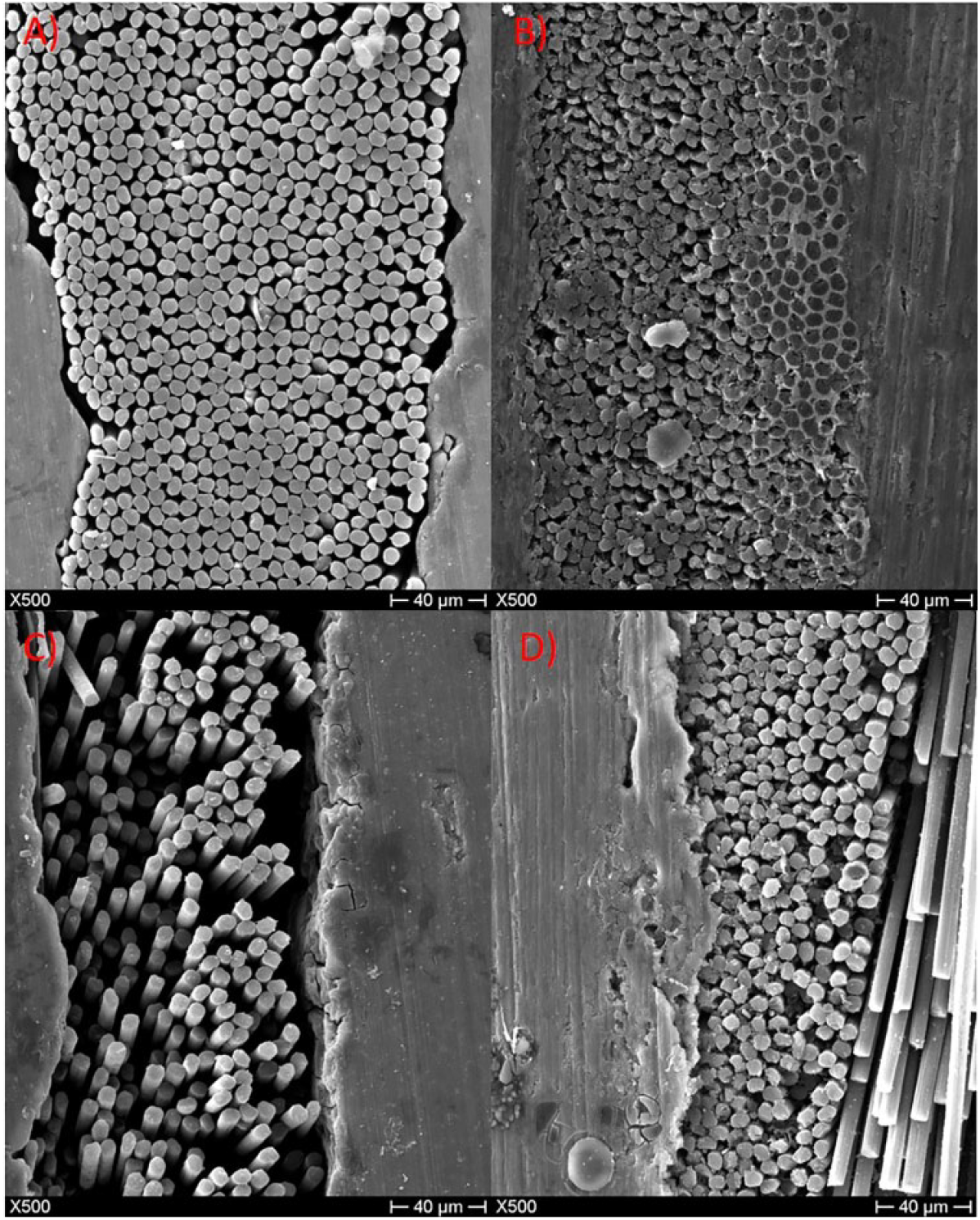
SEM analysis of: A) CWF as received in aluminum matrix; B) CWF with Ni coating in aluminum matrix; C) CWF as received in magnesium matrix; D) CWF with Ni coating in magnesium matrix.
A possible explanation of this phenomenon is that fabric internal filaments are not homogeneously and completely coated during Ni deposition, because of the high quantity of filaments for each wire and overlapping at the intersection of them. Moreover, the capillarity effect resulting from the direct contact between quasi-parallel fibers can explain the impediment to melt penetration. Electroless Ni deposition was carried out onto individual wires (UYFs) obtained from the fabric. Figure 7 shows the results of this approach for the electroless pure nickel plating (deposition ratio 300 ml/g). Fibers are totally and homogenously coated by nickel with a thickness of ~1 µm.
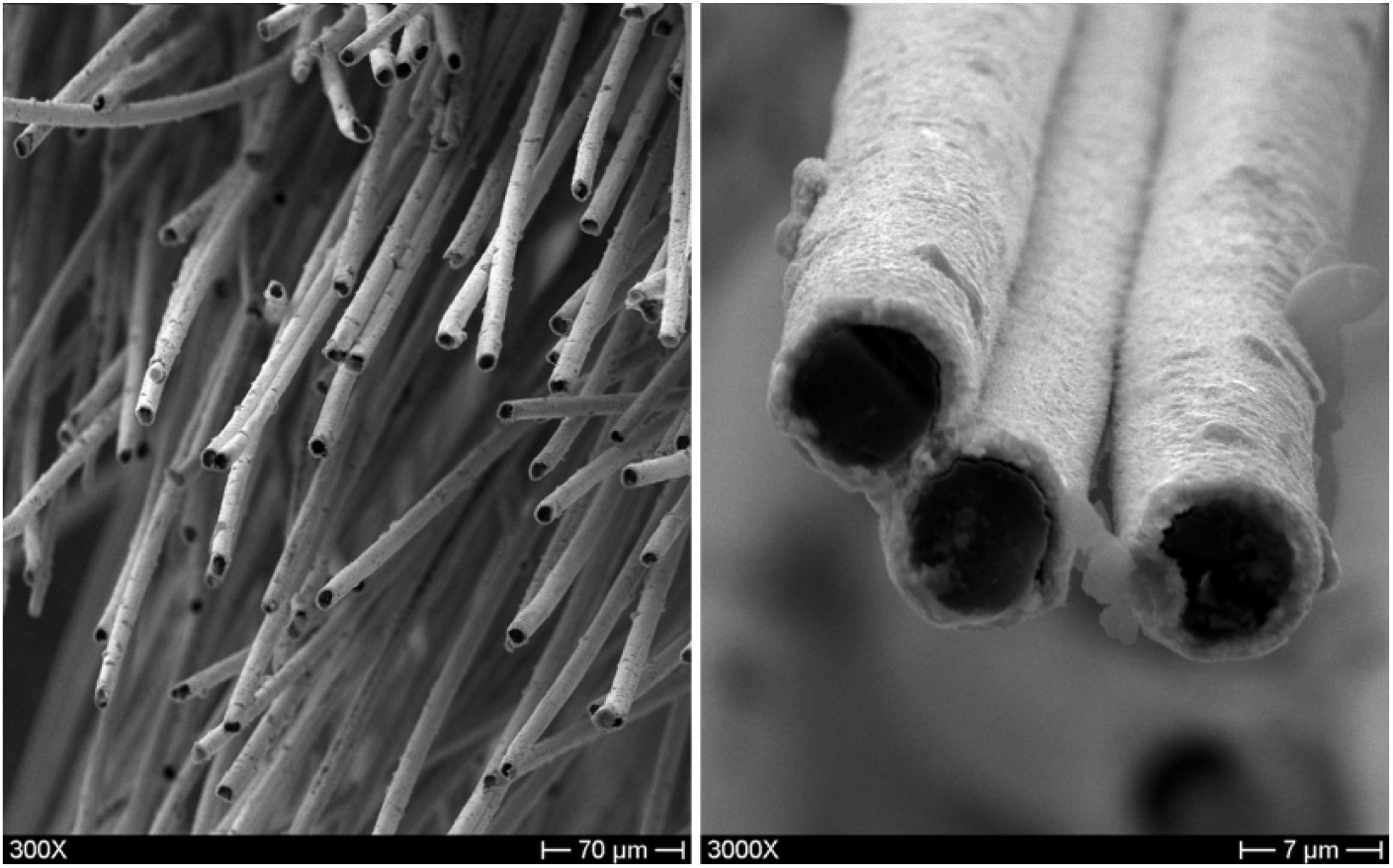
Electroless nickel deposition on UYFs at deposition ratio of 300 ml/g.
No diffusion of nickel was confirmed by EDS analyses performed on as-cast samples of aluminum-based composites with UYFs nickel-coated sandwich structure (Figure 8). In fact, fibers were visible in the matrix and EDS analyses confirmed that contact time between the molten metal and Ni-coated fillers was insufficient to allow Ni diffusion.
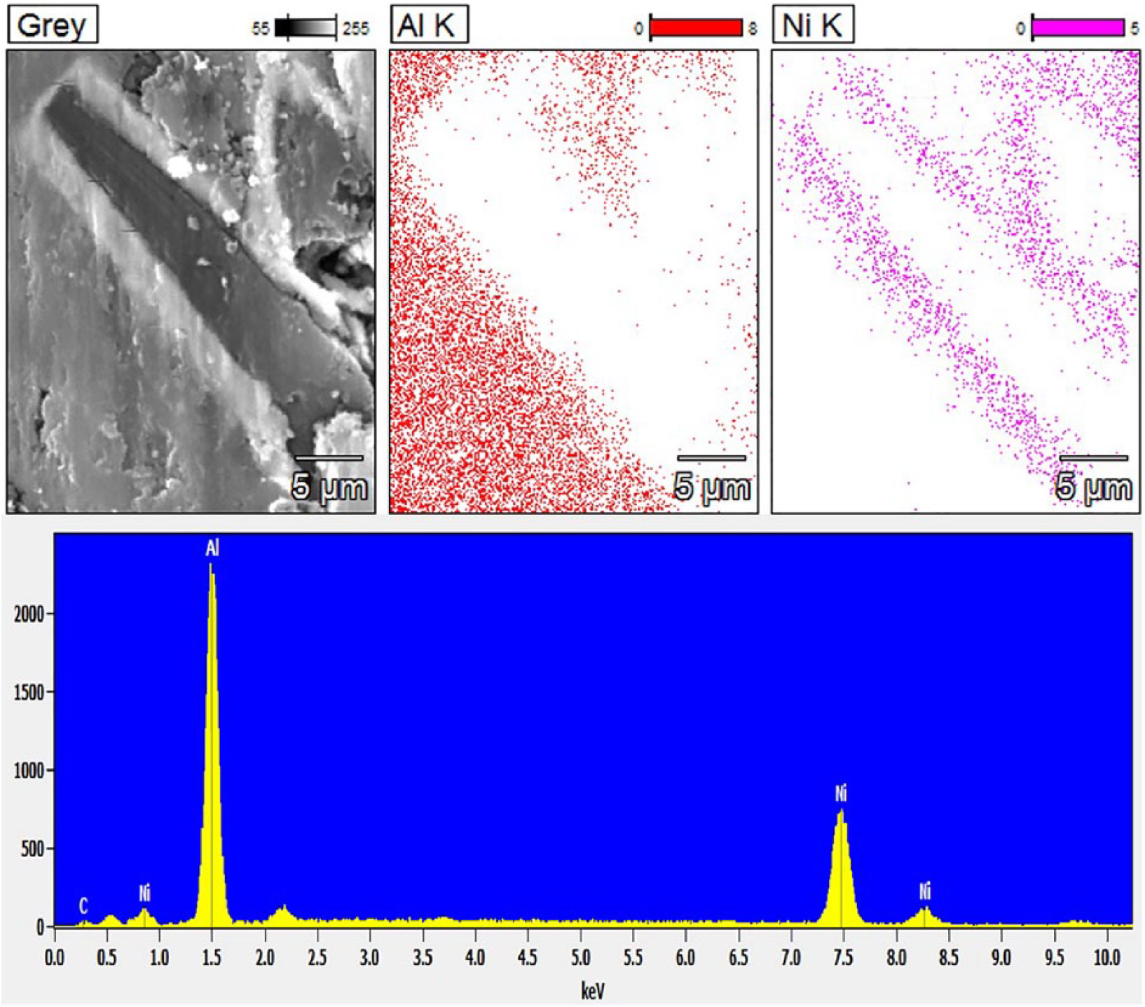
SEM analysis and EDS results performed on composites with UYFs nickel coated.
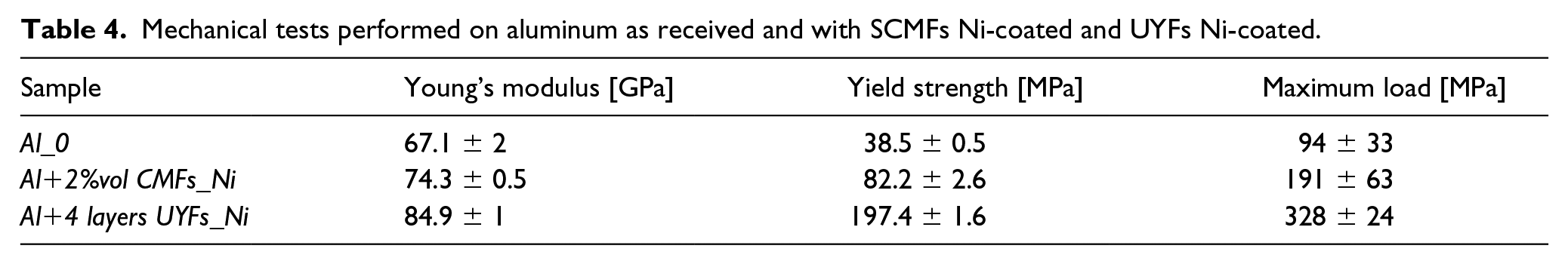
Mechanical tests of pure Al, Al-SCMFs with Ni and Al-UYFs with Ni were compared (Figure 9). In the case of the UYFs, only four layers (around 2%vol) of UYFs with a thick Ni coating were sufficient to obtain an improvement of around 20% of Young modulus and 81% of the yield strength, confirming the increase in interfacial interaction between reinforcement and the metal matrix (Table 4). Finally, Figure 10 shows the interface between Al/Ni and Fiber/Ni.
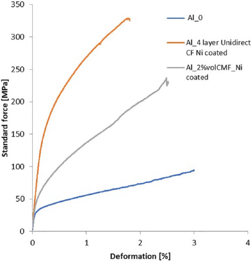
Results of bending tests performed on aluminum composites (Al bulk, Al-SCMFs coated with Ni, and Al-UYFs coated with Ni).
Mechanical tests performed on aluminum as received and with SCMFs Ni-coated and UYFs Ni-coated.
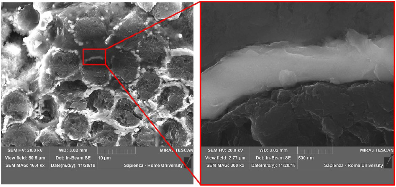
SEM analysis at high magnification of interaction between Al/Ni and Fiber/Ni on a single filament.
Conclusion
Electroless pure nickel plating was demonstrated as a good functional coating to increase the wettability, the interaction, and the dispersibility of carbon fibers onto MMCs. Furthermore, a new manufacturing process for metal matrix composite with Al and AZ63 was described. Induction melting and centrifugal casting to produce Al and AZ63 matrix composites reinforced with SCMFs, CWFs, and UYFs were also studied. This manufacturing process was used in two different modalities, depending on the type of reinforcement used; in particular, melting and casting of metal matrices and premixed SCMFs, and melted metal impregnation in the case of CWFs and UYFs. Good impregnation of fibers and increased mechanical properties were obtained in the case of Al-UYFs composites. Results obtained by 4-point bending tests were compared with results obtained by SEM, EDS, and density analyses in order to evaluate the optimized procedure to produce these composites.
For the future, the development of an injector that feeds the fibers into the casting flow will be analyzed in order to both limit contact time between nickel coating and molten metal and to explore the possibility of obtaining metal matrix SCMFs coated with Ni composites.
Footnotes
Declaration of conflicting interests
The author(s) declared no potential conflicts of interest with respect to the research, authorship, and/or publication of this article.
Funding
The author(s) received no financial support for the research, authorship, and/or publication of this article.