
Abstract
Objectives:
A root canal sealer that can increase the resistance of endodontically treated teeth to compressive strength would be of great advantage. The purpose of this study is to use three different nanoparticles: multi-walled carbon nanotubes (MWCNTs), Titanium carbides (TC), and Boron nitrides (BN) into a bioceramic adhesive root canal sealer; BioRoot™ RCS, in an attempt to improve its structural and compressive strength properties.
Methods:
Three composites of two weight fractions (1- and 2-wt.%) were produced by mixing each nanomaterial separately with a pre-weighed mass of Bioroot powder. The microstructural properties and compressive strength of the different hardened composites obtained were investigated. The composites have been characterized by X-ray Diffraction, Fourier transform infrared spectroscopy, and scanning electron microscopy. Compression testing was performed.
Results:
The 1-wt.% composites, Bioroot/MWCNTs, and Bioroot/TC, except for the one reinforced with BN, displayed a significant improvement in the compressive strength compared to pristine BioRoot™ RCS. The 2-wt.% composites showed no significant improvement in the compressive strength.
Conclusion:
The addition of 1-wt.% MWCNTs and TC nanomaterials can be considered in the future for enhancing the microstructure and compressive strength properties of pristine BioRoot™ RCS.
Keywords
Introduction
Thinning and weakening of root canal walls may occur due to excessive pressure during root canal cleaning and shaping, over-instrumentation, removal of intracanal post, previous endodontic treatment, internal root resorption, and or dehydration due to the application of irrigating solutions. As a result, the resistance of root canals to functional loads may decrease and the roots become more susceptible to fracture1,2 which can eventually lead to tooth loss. Thus, obturating material that can strengthen and reinforce the root canal system against fracture would be ideal.
The field of endodontics is constantly changing due to the introduction of new techniques and technological advances. Advances in endodontic material science, like the recently introduced bioceramic root canal sealers, have contributed significantly to the exponential growth in this field and changed the face of endodontics. It is believed that root canal sealers that are capable of bonding to root dentin can increase the fracture resistance of endodontically treated teeth. 3
Bioceramic-based root canal sealer like BioRoot™ RCS is one of the recent root canal sealers based on tricalcium silicate material that benefit from both active bio-silicate technology and biodentin.4,5 A major benefit of this sealer is its adhesive properties to the root canal walls and its bioactive property that may induce hard tissue deposition.6,7
Bioceramics have become an increasingly important class of biomaterials as alternatives to metallic materials for their biocompatibility. 8 Endodontic treatment has benefited from a variety of tricalcium silicate root canal sealers that have good biocompatibility, yet scarce information exist concerning the efficiency of their mechanical properties. Rafiee et al., 9 and Walker et al., 10 manifested that reinforcing a ceramic-matrix with graphene, can allow excellent toughness, and can impede crack propagation.
In addition to that, and due to the brittleness of bioceramics, new evolutions in the field of nanocomposites has led to the use of nanoparticles as reinforcements to refine the mechanical features of ceramics. 11 Currently, the practical use of nanomaterials for a variety of dental applications have evolved. 12 The outstanding properties of multi-walled carbon nanotubes, titanium carbide, and boron nitride have promoted the synthesis of new composites with beneficial versatile properties.13,14
Carbon nanotubes can significantly improve the properties of ceramic materials and their structural strength.15,16 The combination of its unique mechanical properties and bioactivity renders CNTs as one of the most favorable reinforcement nanomaterial to be used in manufacturing bioceramic nano-composite materials.17–21 Titanium carbide is an extremely hard refractory ceramic material that has many attractive properties such as low density, relatively high thermal and electrical conductivity, and high compressive strength.22,23 Coating with this ceramic improves wear resistance, temperature stability, and friction of composite materials for different applications. 24 Furthermore, Hauert and Patscheider 25 stated that the toughness, thermal stability and environmental compatibility of the composite material improved with the addition of these coatings. Due to their high oxidative properties, mechanical, and chemical resistance, boron nitride nanotubes are gaining more attentiveness as novel nanomaterials. 26 All of the above could be used as reinforcement nanomaterials for improving the mechanical properties of bioceramics. A recent study investigated the physiochemical properties of BioRoot™ RCS reinforced with MWCNTs, TC, and BN. 27 Yet, scarce literature studied the structural changes and compressive strength of BioRoot™ RCS associated with the different nanomaterials.
Based on the issues discussed above, the aim of this study is to investigate the microstructural properties and compressive strength of BioRoot™ RCS after incorporating different nanomaterials that might produce a composite with enhanced properties in comparison to pristine BioRoot™ RCS.
Materials and methods
Materials
This in vitro study was conducted on BioRoot™ RCS root canal sealer (BioRoot™ RCS, Septodont, Saint-Maur-des-Fossés, France). In Table 1, the initial materials’ specifications, manufacturers, and composition used to manufacture the different composites used in this experiment were listed and reproduced from the study by Baghdadi et al. 27 The nanomaterials that were added into the sealer were: multi-walled carbon nanotubes (MWCNTs) with an internal diameter of 3–5 nm, an external diameter of 6–13 nm, titanium carbide (TC) nano-powder with diameter ˂200 nm, and boron nitride nanotubes (BN) with diameter ˂300 nm. All of the ingredients were the products of Millipore Sigma, Burlington, MA, USA, and were used without any additional refinement.
Materials, manufacturers, and composition of the tested sealer and nanomaterials.

This table was reproduced from the study by Baghdadi et al. 27
Manufacturing the composites
To prepare the desired composites, a definite value of Bioroot powder was meticulously weighed. Then, each of the nanomaterials mentioned above, were prepared with 1 and 2 wt.% and mixed with Bioroot using a centrifugal ball milling machine (Model S100, Retsch GmbH, Haan, Germany). In order to produce a homogenous mixture, milling was carried out for each composite using first a speed of 300 rpm for a period of 10 min followed by another cycle at a speed of 100 rpm for 50 min.28,29
In order to harden the composite powder, the liquid solution of Bioroot was added to each composite at room temperature and with of 1:5 (powder to liquid) ratio following the instructions of the BioRoot™ RCS manufacturer. To be able to mix all the powder, an additional drop of liquid was needed in the 2-wt.% composites. 27
Specimen preparation
After manipulation of the composites, the specimens for compression testing were prepared by carefully condensing each obtained composite into especially fabricated cylindrical split stainless steel mold (10 samples/group) measuring 4 mm in diameter and 6 mm in height according to ADA specification #66. 30 Specimens for pristine Bioroot were also prepared in the same way.
The material necessary to make the specimens was weighed using a precision balance and mixed with a plastic spatula on a glass slab to obtain homogenous mixtures. After mixing, the material was inserted slowly in increments of thin layers into the stainless steel molds that were fabricated. During the insertion and packing, the molds were filled slowly till the top in order to adapt the material to the mold and avoid bubble formation. After the insertion of the material, a strip of a metal matrix coated with a separating medium was placed on the top of the surface followed by a glass slab pressed manually to obtain a uniform flat surface. The specimens were prepared at a room temperature of 23° ± 20° and relative humidity of 50% ± 10% as recommended by ADA specification. 30 The molds were placed in an incubator at 37°C and 95% humidity till complete setting. The specimens then were removed from the molds, ground and polished using polishing discs. The specimens were tested after 7 days.
Microstructural analysis
X-ray diffraction (XRD)
XRD is a technique utilized to analyze the crystal structure of a material by studying the interaction between incident x-ray beams and the surface. It was used to analyze the phase structure of the pristine BioRoot™ RCS and the formed composites. The XRD device used for the specimens’ evaluation was a DB Focus, Bruker ASX GMBH Kaarsruhe model made in Germany. The diffractometer was operated at 40 kV and 30 mA at a 2θ range of 10°–90° employing a step of 5 s per step.
Fourier-transform infrared spectroscopy (FT-IR)
Fourier Transform Infrared spectroscopy (FTIR) (JASCO FT/IR-6300 FTIR spectrometer) was applied to investigate the presence of functional groups, formation of intermolecular bonds and distribution mechanism of the different nanoparticles that were added in comparison to the pristine BioRoot™ RCS.
Compressive strength test
The specimens prepared were mounted on a Universal Testing Machine (YL-UTM Main, YLE GmBH) at a crosshead speed of 1.0 mm/min. The specimens were positioned vertically to their long axis for the compressive strength test with the force applied perpendicularly and continuously on the specimen (Figure 1(a) and (b)). The compressive strength was calculated by dividing the maximum load carried by the specimen during the test by the average cross-sectional area of the specimen according to the following formula:

(a) Schematic illustration of compressive strength adapted from Darvell (BW, 2000), 2000 and (b) Real image of the testing procedure.
Scanning electron microscopy (SEM)
Scanning electron microscope is a useful technique for investigating microstructural properties such as micro-cracks. In this study, a high emission electron microscope (Type TESCAN) was used to examine the influence of adding nanomaterials on the microstructure of the fractured specimens of pristine Bioroot and the composites.
Statistical analysis
One-way ANOVA (analysis of variance) was applied for the compressive test where the isolated factors were pristine Bio Root™ RCS and its composites. The decision rule for the F-test is for each one-way ANOVA detected significant with statistical differences (p-value ⩽ 0.05) among the means of each composite. In this case, the Tukey test was applied to determine which composite was statistically different.
Results
Crystal structure through XRD
Figure 2 shows the XRD patterns of pristine CN, TC, and BN prior to their incorporation into the pristine Bioroot. It was observed that pure CN exhibit a graphitic peak located at around 2θ = 25.6 and signifying the (002) plane,31,32 while pure TC shows high intensity peaks at 2θ = 36°and 42° and signifying the (111 and 200) plane structures.33,34 As for pure BN, the peak found at 2θ = 26.6° signifies (002) plane reflection of the hexagonal BN structure. 35

XRD patterns of pristine CN shows a graphitic peak at 25.6°; pristine TC shows peaks at 36.87° and 41.98°; pristine BN shows a peak at 26.6°.
The phase analysis of pristine set BioRoot™ RCS is shown in Figure 3 and compared to that of the manufactured composites. No wide amorphous peaks were observed in the diffractogram. The sharp peaks at 28.4°, 32°, 34.4°, and 41.4° were indicative of a tricalcium silicate phase. 36 The peak at 34° was additional proof that calcium hydroxide was present in the mixture as a result of the hydration reaction. 37 In addition, the peaks around 49.4° and 50.2° indicate the presence of zirconium oxide. 38

XRD diffractogram for pure Bioroot showing the crystalline phases: TCS, tricalcium silicate, CH, calcium hydroxide; and ZO, zirconium oxide; Bioroot/1 and 2-wt.%MWCNTs show in addition to the Bioroot phases, an additional peak assigned to the hexagonal graphitic structure of MWCNTs; Bioroot/1-wt.%TC showing same phases but with decrease in peaks intensity and an additional peak for TC; titanium carbide; Bioroot/2-wt.%TC show an additional peak at 59.70 similar to pure TC and no change in peaks intensity; Bioroot/1 and 2wt.%BN show no major change in the material structure.
Observing the pattern of Bioroot/CN composites, the diffraction peaks relevant to pure Bioroot did not change. The additional peak at 25.6° was designated to the (002) plane of the hexagonal graphitic structure of the carbon nanotubes. 39 A slight shift in all the peaks of the 2 wt.% Bioroot/MWCNT was observed and might be due to error in the device setting.
In the composites with TC, the diffraction peaks showed an additional peak for TC at 36° and 42°. The peaks representing BioRoot™ RCS were also still present with the addition of 1-wt% TC, however, the intensity of the peaks decreased. In the 2-wt.% Bioroot/TC composite, the increased amount of TC to 2-wt% didn’t change the intensity of the peaks.
In the composites with BN, no major change in the material crystal structure could be detected in the XRD graphs.
Chemical structure through FTIR
The results of FTIR analysis of the pristine BioRoot™ RCS set sample and its 1 and 2-wt.% composites are shown in Figure 4. The broad presented peaks at 3350 and 3594 cm−1 represent stretching motions of hydroxyl ions in the crystal network of BioRoot™ RCS and its composites. The broad peak at 3350 became less pronounced in the 1-wt.% composites compared to pristine BioRoot (Figure 4(a)). The opposite trend was seen for the 2-wt.% composites.
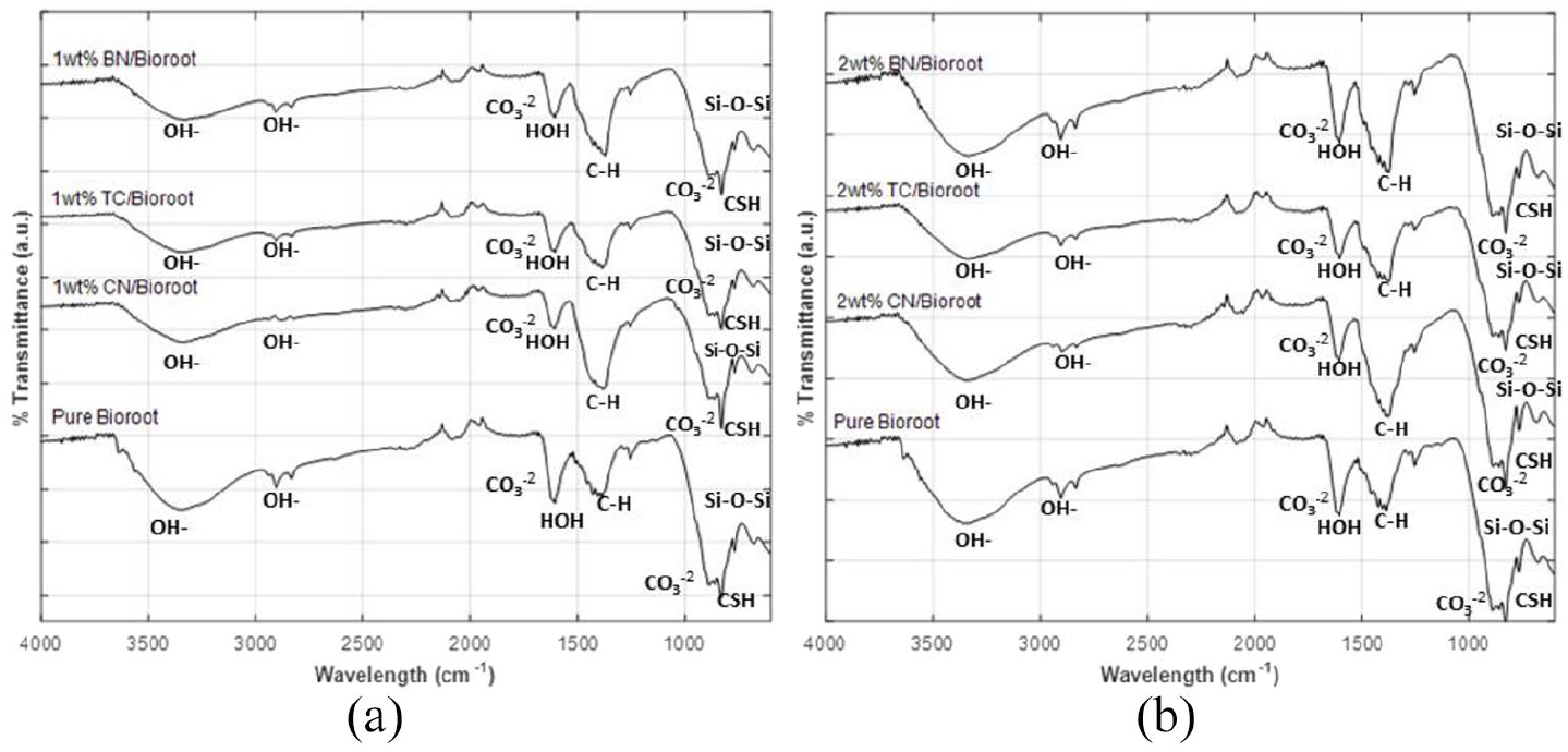
FTIR spectra of pure BioRoot and its composites for (a) 1-wt.% Bioroot/CN and Bioroot/TC showing peaks representing stretching motions of hydroxyl ions OH-, C-H, C=O and C-O bands in the network of the Bioroot matrix; Bioroot/BN shows no interaction between BN and Bioroot matrix (b) 2-wt.% Bioroot/CN and TC are similar to 1-wt.% with less hydroxyl peaks; Bioroot/BN shows inverted peak with no interaction with Bioroot matrix.
The shoulder at 3594 almost disappears in the 1- and 2-wt.% composites. In all the 1-wt.% composites, the added nanoparticles relatively decreased the intensity of the hydroxyl peaks in comparison with the pure BioRoot™ RCS. In the 2-wt.% composites (Figure 4(b)), the same observed peaks were more pronounced.
The observed peaks at 2935, 2900 cm−1, and in addition to a bent peak at 1476 cm−1 represent stretching motions of C-H in alkane group. The peaks ranging from 1733, 1619 and 1607 cm−1 and the peaks at 1170 cm−1 and 1733 cm−1 are associated with stretching bands of C=O and C-O respectively shown more in MWCNT and TC composites. The bent peaks ranging from 828 till 892 cm−1 are associated with Si-O-Si stretching vibrations and Si-(CH3)3.
Compressive strength (CS)
The results of the compressive test for pristine BioRoot™ RCS and its composites are presented in Table 2. The p-value corresponding to the F-statistic of one-way ANOVA is ˂0.05, implying that the one or more loads are significantly different. The Tukey HSD test, for multiple comparison tests followed in which we only reported the pairs that are significantly different. Post-hoc tests were used to explore the differences between the pairs of means that are significant (Table 3).
Mean Compressive Strength (CS) in MPA and standard deviations (SD) of pure Bioroot RCS, 1-wt.%, and 2-wt.% composite.
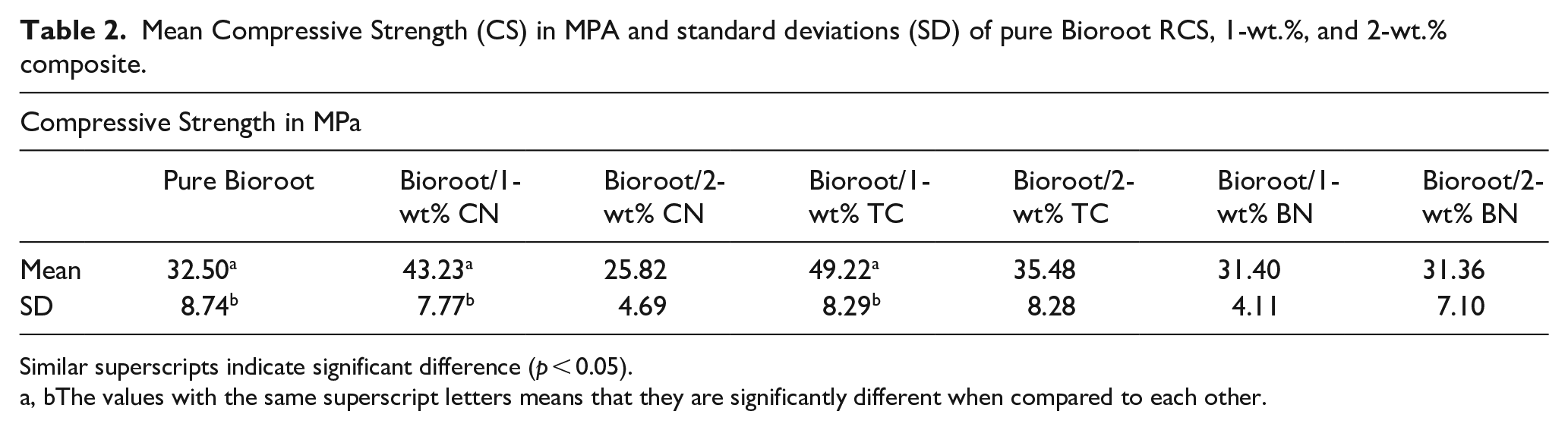
Similar superscripts indicate significant difference (p < 0.05).
a, b The values with the same superscript letters means that they are significantly different when compared to each other.
Post hoc or paired comparison table showing the pairs that are significantly different.

The results showed that the incorporation of 1-wt.% MWCNT and TC had a significant effect on the increase of the compressive strength of pristine BioRoot™ RCS (up to 16.7%) with no significant difference between both composites (Figure 5).
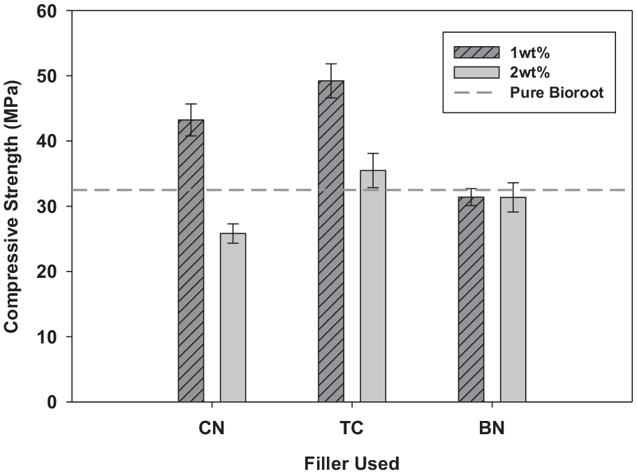
Mean Compressive Strength (CS) of pure Bioroot RCS, 1-, and 2-wt.% composites: The figure shows a significant increase of compressive strength in the two composites 1-wt% Bioroot/CN and Bioroot/TC. There was no significant difference in the compressive strength between Bioroot and the rest of the composites.
Contrarily, the 2-wt.% composites containing MWCNTs and TC showed no effect on the compressive strength of pristine BioRoot™ RCS with no significant difference between both composites. Consequently, the compressive strength for the 2-wt.% composites was lower than that of the 1-wt.% composites.
As for the incorporation of 1- and 2-wt.% of boron nitride, it exhibited no effect on the compressive strength of pristine BioRoot™ RCS.
Scanning electron micrograph analysis
The images that were taken by electron microscope analyses are presented in Figure 6. It can be observed from these images that the irregular nanometric size of the bioceramic particles, revealed a structure incorporating the Bioroot powder that is composed mainly of tricalcium silicate and zirconium oxide, and its liquid which is an aqueous solution of calcium chloride and polycarboxylate (Figure 6(a)). Also, it was observable in the homogenous field of Bioroot, agglomerated semi-sphere nanoparticles that were less than 150 nm. In all its composites, an indistinguishable image was detected compared to the pristine Bioroot material.

Fracture surface for (a) pristine BioRoot™ RCS shows irregular size of bioceramic particles ˂100 nm in an integrated cracked structure of Bioroot, (b) 1-wt.% Bioroot/CN shows crack propagation on surface of the composite with carbon nanotubes bridging micro-cracks, (c) 1-wt.% Bioroot/BN shows cleavage fracture with no evidence of interfacial bonding (d) 1-wt.% Bioroot/TC shows fine particles reinforcement and good interfacial bonding, (e) 2-wt.% Bioroot/CN shows nanotubes that are non-uniformly dispersed in the Bioroot matrix with agglomeration, (f) 2-wt.% Bioroot/BN shows a similar image to Bioroot/1-wt.%BN, (g) 2-wt.% Bioroot/TC shows a crack propagation and particle fracture along the surface.
In the 1-wt.% Bioroot/MWCNT composite, multi-walled carbon nanotubes were dispersed in the whole composition (Figure 6(b) and (d)). In the 2-wt.% composites, it could be seen that they were non-uniformly dispersed in the matrix of pristine Bioroot and that larger crystals has been detected. The same as many other nanomaterials, the agglomeration of nanoparticles is unavoidable and was observed more in the composites of higher percentage. Figure 6(b), illustrates the crack propagation on the surface of 1-wt.% Bioroot/MWCNTS composite.
In the Bioroot/1-wt.%TC, fine particles of the titanium carbides, homogeneously distributed in its matrix, were visible on the micrograph (Figure 6(d)). Intergranular and trans-granular fractures are observed. With increasing the load, the crack continues in a stable manner. The presence of TC in the form of clusters is observed along the surface of the composites with 2-wt.% TC (Figure 6(g)). Debonding of the particles is also observed due to the increase in the hard and sharp TC nanoparticles. With further increase in the weight percentage of TC, propagation of cracks, micro cracks and fracture of the nanoparticles are evidenced along the surface indicating a brittle mode of fracture.
In the composites reinforced with boron nitride (BN), BN occurred in lower concentrations compared to the other nanomaterials (MWCNTS, TC). This interprets the cleavage fracture with no interfacial bonding between BN and the Bioroot matrix that was evident in both concentrations (Figure 6(c) and (f)).
Discussion
Crystal structure evaluation through XRD
In this study, the XRD analytical technique was primarily used for phase identification of the crystalline material pristine BioRoot™ RCS and its composites. The use of XRD allowed the identification of the main compounds present.
The phase analysis of pristine set BioRoot™ RCS showed peaks indicative of a tricalcium silicate phase 36 calcium hydroxide that was present in the mixture as a result of the hydration reaction 37 and zirconium oxide. 38
Observing the pattern of Bioroot composites with CN, diffraction peaks relevant to pure Bioroot did not change indicating that the material was not affected by the addition of CN in terms of crystal structure. The additional peak at 25.6° was designated to the (002) plane of the hexagonal graphitic structure of the carbon nanotubes. This indicates that the process of deposition of the nanoparticles in the composites preparation and mixing phase did not damage the hexagonal graphitic structure of the MWCNTs. 39
With the addition of 1-wt% TC, it was noticed that the peaks representing BioRoot™ RCS were also still present however, the intensity of the peaks decreased. It can be hypothesized that the composite components created an amorphous structure where the molecules exhibited a possible physical interaction. On the other hand, when the amount of TC was increased to 2-wt%, the intensity of the peaks didn’t change.
Given that the density of BN is much higher than MWCNTs and TC, it is speculated that 1- and 2-wt.% of BN are much less in volume than the other nanoparticles that were added. For this reason, major change in the material crystal structure was not as strong in intensity as to be detected in the XRD graphs
Evaluation of the chemical structure through FTIR
The FTIR analysis method uses infrared light to scan test samples, observe chemical properties, and investigate the presence of chemical functional groups. In this study, we used this analytical technique to analyze the formation of inter-molecular bonds and distribution mechanism of the different nanomaterials that were added to the pristine BioRoot™ RCS.
The peaks at 3350 and 3594 cm−1 representing stretching motions of hydroxyl ions in the crystal network of BioRoot™ RCS and its composites, relatively decreased in intensity in the 1-wt.% composites compared to pristine BioRoot and the 2-wt.% composites. This variation might be attributed to the formation of weak hydrogen bonds. 31 The opposite trend was seen for the 2-wt.% composites. It can be concluded that when the percentage of the nanoparticles was increased from 1 to 2-wt.%, the hydroxyl peaks became more noticeable for all the composites which means that fewer bonds were formed.
The observed peaks at 2935, 2900 cm−1, in addition to a bent peak at 1476 cm−1 represent stretching motions of C-H in alkane group. The diversity in location and intensity of interactions show some interactions between MWCNTs and the Bioroot matrix and between TC and the Bioroot matrix. However, the inverted peak in the Bioroot/1-wt.% BN shows no interaction between BN and the Bioroot matrix.
In the Bioroot/MWCNT and Bioroot/TC composites, the C=O possibly show high bonding between water in the liquid of Bioroot and the carbon in the nanomaterials which possibly might explain the decrease in the intensity of the hydroxyl peak in both groups. In fact, because of the distribution of the MWCNT and TC nanoparticles in the bioceramic constituent of BioRoot™ RCS, the significant increase in the compressive strength might be explained. The crosslinking between carbon and oxygen, and carbon and hydrogen, is accompanied by reinforcement of the BioRoot™ RCS. In the Bioroot/TC composite possibly the hydrolysis of TC proceeded according the reaction TiC + H2O to produce CH4 (methane) + TiO2 + H2O.
According to the data of the FTIR, intact MWCNTs are adsorbed by water at room temperature. 40 Water molecules adsorbed in a state that is similar to liquid water are consistent with peaks observed at 1619, 1170, and 3350 cm−1. The large intensity of these peaks indicates that most water molecules adsorb into this state integration of the peak areas of the 0–H stretches. Since the peak at 3350 cm−1 was observed in all the composites then it is more reasonable to have the water adsorbed on the Bioroot matrix itself too.
Compressive strength (CS)
The compressive strength has a particularly important role in the mastication process since several masticatory forces are of compressive nature. It was used in this study because it renders a good portrayal of the mechanical integrity of brittle materials like glass ionomers and bioceramics. 41 In determining the compressive strength, two axial forces were applied to the material in opposite directions, thus bringing its molecular components close together. 42
The results showed enhancement in the compressive strength of the reinforced pristine BioRoot™ RC than in Bioroot alone. A higher compressive strength was observed when lesser amounts of nanomaterials were added. The maximum strength was observed in the 1-wt.% composites except for the composite containing BN. One explanation of why the 1-wt.% BN had no significant effect is its large particle size and its high density which leads to very little added amount when calculated by weight percentage not by volume. Smaller size nanoparticles of lower density maybe considered for future work.
The significant increase of compressive strength in the 1-wt.% Bioroot/MWCNTS and Bioroot/TC composites might be due to the formation of crystal phases in the structure of pure Bioroot. Figure 6(b) represents the SEM image of the paths produced by the crack propagation after performing the compression test. MWCNTs in the wake of propagation crack, might strongly suggest a bridging effect during crack propagation, thus enhancing the strength of the composite.43,44
On the other hand, reinforcing pristine BioRoot™ RCS with 2-wt.% of the three different nanomaterials, had no significant increase in its compressive strength. This may be due to improper dispersion or higher degree of entanglement of the nanomaterials due to higher amounts being utilized. 45 They act as a barrier and tend to agglomerate making it more difficult to be evenly dispersed into the Bioroot matrix, thus, preventing them from complete bonding to the matrix. This results in a decrease in the bonding forces between the ceramic part and the matrix leading to strength reduction which is in agreement with what have been reported in the literature.46,47 Hence, the compressive for the 2-wt.% composites was lower than the 1-wt.% composites.
A lower water/powder ratio of the amount of water to the weight of the powder leads to a higher compressive strength. 48 In the 2-wt.% composites, and to be able to wet the total amount of the powder, an extra drop of liquid was needed. 27 This difference in proportion is a factor to be considered and may have contributed to the reduction of the compressive strength in the composites of higher percentage.
In addition to that, the agglomeration of nanoparticles in higher percentages may be another factor. One study showed that the reduced compressive strength of MTA with the addition of nano-particulate calcium carbonate (NPCC) may be related to the possibility of agglomeration when they are used in higher concentrations.49,50 Higher NPCC content can lead to the partial replacement of cement by an inert material resulting in lower hydration and a weaker microstructure. 51 In addition, nanoparticulates tend to agglomerate and the van der Waals force becomes stronger between them than in the cement thus creating zones of weakness in the material microstructure. 52 Attempts have been made to add carbon nanotubes in cementitious matrices at an amount ranging from 0.5 to 2.0 wt.%. 53 Kowald incorporated 0.5% MWCNTs and observed 12% increases in compressive strength. 54 The study of Siddique and Mehta 55 showed that the use of CNTs decreased the porosity of the cement, reduced the total pore volume, and increased the compressive strength.
Scanning electron micrograph analysis
The scanning electron micrographs were used to confirm the improvement in the mechanical properties by displaying changes in the surface and crack morphology of the fractured samples of pristine BioRoot™ RCS and its composites.
The phase analysis of BioRoot™ RCS exhibited two main phases: tricalcium silicate phase as the cementitious material and a radio-opacifier phase composed of zirconium oxide and tantalum oxide. 34
Multi-walled carbon and titanium carbide nanotubes tend to be aggregated and come in accumulation or can be found at scattered points that might have established physical bonding with the cement matrix. In the 1-wt.% composites containing MWCNTs and titanium carbides, the agglomerates were separated and dispersed in a cementitious matrix, thereby helping to improve their compressive strength property. On the contrary, the opposite was found in the 2-wt.% composites, which is the same as many other nanomaterials, where the agglomeration of nanoparticles is inevitable in higher percentages as reported by other researches. 56
The addition of carbon nanotubes in the matrix of pristine BioRoot™ RCS resulted in increase in the peak width, and thus a decrease in the crystal size. This is interesting for ceramics, as it could simultaneously increase its strength due to the change of cracking mode from trans-granular to intergranular and the deflection of propagating cracks. 57
The formation of smaller nanocrystals with the presence of MWCNT, compared with the pristine Bioroot, provide more reactive surface and a nucleation site for the formation of calcium silicate hydrates which leads to a denser microstructure and thus might increase the compressive strength of the composite. According to Figure 6(b), carbon nanotubes made bridges on the micro-cracks in the Bioroot matrix and caused a decrease in the production of calcium hydroxide functional groups. Moreover, bridging and filling the micro-pores led to an increase in the compressive strength the Bioroot RCS composite reinforced with 1-wt.% MWCNTs and TC nanotubes, which was consistent with the compressive test results.
From the energy criterion theory, the crack will propagate through the tricalcium silicate phase when the energy needed is sufficient to overcome the resistance of the material or when it gets restricted or deflected creating a more tortuous path to release stress when in close proximity to multi-walled carbon nanotubes and titanium carbides. 58 This is in agreement with studies that have also shown that graphene bridging is effectual for the toughening of ceramics–graphene composites.10,44,59 Moreover, the high surface area of MWCNTs allowed for strong interfacial bonding between them and tricalcium silicate, which minimized porosity formation.
On the other hand, higher percentages of nanoparticles (2-wt.%), caused agglomeration and higher porosity which is believed to provide nucleation sites for fracture and thus weaken the strength of the ceramic composites, which might explain the lower compressive strength results in the 2-wt.% composites. 60 This may explain the fact that the addition of more than the optimum amount lead to weaker composites. 61
The finding of hard ceramic particles (TC) in the matrix was not the only reason to raise the strength of the composite but also it depended on grain size of reinforcement, good interface bonding and the structure of the composite. 62 In the Bioroot/1-wt.%TC, fine particles of the titanium carbides, homogeneously distributed in its matrix were visible on the micrograph of nano-composite. Intergranular and trans-granular fractures were also observed. With increasing the load, the crack continued in a stable manner. The addition of titanium carbide nanomaterials increased the interfacial bonding between them and the Bioroot matrix. They offered resistance to fracture which might be also attributed to stronger bonding between particle and matrix interfaces.
The presence of TC in the form of clusters was observed along the surface of the composites with 2-wt.% TC (Figure 6(g)). Debonding of the particles was also observed due to the increase in the hard and sharp TC nanoparticles. With further increase in the weight percentage of TC, propagation of cracks, micro cracks and fracture of the nanoparticles were evident along the surface indicating a brittle mode of fracture.
In the composites reinforced with boron nitride (BN), the hexagonal BN layers are bonded by weak van der Waals force, which enables the layers to slide easily against each other. 26 BN occurred in lower concentrations compared to the other nanomaterials (MWCNTs, TC) due to its high molecular weight that affected its weight percentage the powder production process compared to MWCNTs and TCs. This interprets the cleavage fracture with no interfacial bonding between BN and the Bioroot matrix that was evident in both concentrations (Figure 6(c) and (f)).
An overall analysis of the structure indicates that the reinforced particles were uniformly distributed in the Bioroot matrix in the 1-wt.% composites although clustering is seen in some places in the composites. This can be attributed to the fact that there was a very good interaction between the hydration products and the dispersed MWCNT and TC nanomaterials; consequently, this produced a denser microstructure when compared to the unreinforced BioRoot™ RCS. They formed a denser matrix and therefore, they significantly prevented the spread and release of micro-cracks.
In higher percentages (2-wt.%), the lack of the nanomaterials’ uniform distribution due to their agglomeration, negatively affected the microstructural properties of the composites. 63 Thus, the brittle nature was induced and was responsible for the reduction in the compressive strength due to the development of stress concentration areas in the composite leading to the initiation and propagation cracks that caused de-bonding of the matrix at their interface.
It seems prudent when choosing a material not to consider mechanical properties as isolated factors. Comparisons of laboratory tests for the materials used in this study may not reflect a clinical situation appropriately. Further studies to investigate other physio-chemical and mechanical properties as well as chemical composition and biocompatibility are required to better understand the properties of these new composites.
Conclusion
From the results obtained, the following can be concluded:
The results of the XRD and FTIR analysis showed that BioRoot™ RCS was composed primarily of tricalcium silicate, calcium hydroxide, and zirconium oxide. The addition of the nanomaterials did not affect its main composition. The analysis also showed a very good interaction between hydration products and the dispersed MWCNT and TC, which resulted in a denser microstructure compared to pristine Bioroot leading to enhancement of the Bioroot matrix.
Adding nanomaterials (MWCNT and TC) to pristine BioRoot™ RCS significantly improved its compressive strength. These nanomaterials can therefore be considered promising additives for restorative dental materials, provided that higher compressive strength was observed in lower percentages of nanomaterials.
The 1-wt.% MWCNT and TC significantly prevented the spread and release of micro-cracks. However, an adverse trend was detected when the percentage was increased to 2-wt.% leading to slumped properties.
The results revealed that the BioRoot™ RCS reinforced with (BN) nanomaterial had no effect on its microstructure and compressive strength.
The SEM analysis of the fractured specimens showed that there are possible interfacial interactions between the 1-wt.% Bioroot/MWCNT and Bioroot/TC composites and the hydration products of Bioroot, which produced a higher bonding strength between the reinforcements and the cement matrix.
Footnotes
Acknowledgements
The authors acknowledge Associate professor Seifedine Kadry, Beirut Arab University for executing the statistical analysis; Mr. Ziad Chamly for designing and fabricating the custom made molds; Mrs. Nisrene Al Aaraj, chemist and Laboratory assistant Lebanese university for her assistance in the composites fabrication.
Author contributions
The contribution of the authors was divided as such: Clinical sssistant professor Inaam Baghdadi is the corresponding author. Prof. Ziad Salameh is the director of the research and was responsible for conceptualization and editing. Prof. Mirvat Zakhour is the co-director and was responsible for the methodology, data analysis, and validation. Prof. Mutlu Ozcan was responsible for writing, reviewing, and editing. Prof. Belal Abou Tarboush did the formal analysis and investigation of the XRD and FTIR. Prof. Ashraf Zaazou supervised and edited the manuscript. Dr. Hasan Skeinhe supervised the mechanical testing and project administration.All authors have read and agreed to the published version of the manuscript.
Declaration of conflicting interests
The author(s) declared no potential conflicts of interest with respect to the research, authorship, and/or publication of this article.
Funding
The author(s) disclosed receipt of the following financial support for the research, authorship, and/or publication of this article: This research was funded by Amel Association whom we thank for funding and supporting this research.