
Abstract
Introduction:
Pyrolytic carbon (PyC) is a kind of biomaterial which is chemically inert and has excellent biocompatibility. In order to obtain a super-hydrophobic PyC surface to improve anticoagulation and inhibit thrombus, this study prepares grating pair structure, microhole array structure, helix structure on PyC surface by nanoseconds laser etching.
Methods:
Rod-like ZnO film and ball-like ZnO film are prepared on the PyC surface by the hydrothermal method; polyvinyl pyrrolidone (PVP) nanofiber film and PVP/TiO2 complex nanofiber film are prepared on the PyC surface by the electrospinning method; the PyC surface is silanized. Finally, surface microstructure and surface energy are characterized by scanning electron microscopy and contact angle meter (OCA20, German DataPhysics Co.).
Results:
The periodical microstructures are formed respectively by nanoseconds laser etching. The surface roughness is increased by the hydrothermal and electrospinning method.
Conclusions:
Through infiltration experiment on rough and smooth PyC surfaces, rough PyC surface with microstructure is super-hydrophobic and has greater than 150° contact angle, which decreases blood flow resistance and inhibits thrombus.
Introduction
PyC is a kind of biomaterial which is chemically inert and has excellent biocompatibility. It does not produce ions harmful to the body and its chemical property is stable within the body, so it can be used directly in the cardiovascular system. Compared with the natural cardiovascular system, its anticoagulation is inferior. Patients can easily develop thrombus after pyrolytic carbon (PyC) replacement and must receive lifelong antithrombotic therapy. Any ensuing reaction depends on the surface property of the material when the material contacts blood. At present, research on improving anticoagulation of the PyC surface focuses on two aspects: one is to seek material with better blood compatibility; the other is to conduct PyC surface modification. Li et al. implanted nitrogen ion onto the PyC surface by use of ion beam; 1 Ali et al. deposited amorphous diamond (Cr-containing diamond-like carbon) film by magnetron sputtering; 2 Nan Huang et al. deposited TiO2 film by Ion Beam Enhanced Deposited. 3 All these experiments can effectively improve anticoagulation of the PyC surface. All in all, the anticoagulation of the PyC surface can be improved through conducting PyC surface modification by use of ion beam and magnetron sputtering.4–7
Though regarded as the best material for mechanical heart valves with superb blood compatibility up to now, PyC also brings about a series of rejection reactions in the long-term contact with cardiac tissues and blood, giving rise to hemolysis and coagulation, which will impact the normal on–off of heart valve prosthesis and even cause serious bleeding. Consequently, anti-coagulation performance has become a difficulty in heart valve prosthesis research. Present experts on the world scale usually coat the surface of heart valve prosthesis or alter the surface characteristics of film so as to improve its blood compatibility. However, since the heart valve prosthesis has a curved surface, it is hard to guarantee the evenness of coating or film; besides, the integration of coating and foundation material influences its validity period to some degree. In recent years, micro-structures such as nanofiber, nano-tube and nano-belts have been manufactured via an electrostatic spinning method. Take nanofiber as an example: characterized by relatively large specific surface area, unique netted structure, and high porosity, it is widely accessible in the fields of food engineering, drug delivery, tissue engineering, conductive nano-wire, nano-sensor, military biochemical protection clothing, and wound healing, et cetera. This study aimed to take advantage of the electrostatic spinning method to texture nanofiber structure on the PyC surface with super-hydrophobicity, which provides new approaches for promoting the blood compatibility of PyC material. This study takes PyC as the subject and modifies its surface property by nanoseconds laser etching, hydrothermal and electrospinning method to prepare ZnO film, aiming at improving its hydrophobicity to reduce blood coagulation.
Experimental part
Laser etching
Polish three pieces of 5 mm × 5 mm × 1 mm PyC with a polishing cloth and rinse them with deionized water after the oxide layer is removed. Clean them using ultrasonic cleaner. Do ultrasonic cleaning for 30 min with acetone and ethanol in turn and dry them for use. Process three microstructures respectively: grating pair structure, microhole array structure, helix structure. Observe their topography by scanning electron microscopy (SEM) and measure their contact angle by contact angle meter after silanizing with 1 μL water droplets.
For processing the grating pair structure, the parameters are set as 6V voltage, 1 kHz impulse frequency, 60 μm/s processing speed, 20 times the number of repeats, and 100μm line width; for processing the microhole array structure, the parameters are set as 6V voltage, 1 kHz impulse frequency, 100 μm/s processing speed, 20 times the number of repeats, and 100 μm line width; for processing the helix structure, the parameter are set as 6V voltage, 1 kHz impulse frequency, 60 μm/s processing speed, 20 times the number of repeats,100 μm line width with circuitous dotting.
Preparing ZnO film
This experiment prepares two types of ZnO film on a PyC surface by a hydrothermal method, observes their topography by SEM and measures their contact angle by contact angle meter with 1 μL water droplets.
Preparation method of rod-like ZnO film. Polish a 5 mm × 5 mm × 1 mm piece of PyC with a polishing cloth and rinse it with deionized water after the oxide layer is removed. Clean it for 30 min using ultrasonic cleaner. Do ultrasonic cleaning for 30 min with acetone and ethanol in turn and dry it for use. Put the PyC at the bottom of the weighing bottle, wrap it vertically with cleaned zinc flake, prepare 10% formamide solution and add it into the bottle. Put the bottle in the water bath in 70°C reaction temperature for 24 h of reaction time. Make sure to leave some clearance at the mouth of the weighing bottle in the course of the reaction and air dry it after completion of reaction.
Preparation method of ball-like ZnO film. Polish a 5 mm × 5 mm × 1 mm piece of PyC with a polishing cloth and rinse it with deionized water after the oxide layer is removed. Clean it for 30 min using ultrasonic cleaner. Do ultrasonic cleaning for 30 min with acetone and ethanol in turn and dry it for use. Put the PyC at the bottom of the weighing bottle, wrap it vertically with cleaned zinc flake, prepare 12% formamide solution and add it into the bottle. Put the bottle in the water bath in 90°C reaction temperature for 24 h of reaction time. Make sure to leave some clearance at the mouth of the weighing bottle in the course of reaction and air dry it after completion of the reaction.8–10
Electrospinning
This experiment prepares two types of nanofiber film on the PyC surface, observes their topographies by SEM and measures their contact angle by contact angle meter with 1 μL water droplets.
Preparation method of polyvinyl pyrrolidone (PVP) nanofiber film. Polish a 5 mm × 5 mm × 1 mm piece of PyC with a polishing cloth and rinse it with deionized water after the oxide layer is removed. Clean it for 30 min using ultrasonic cleaner machine. Do ultrasonic cleaning for 30 min with acetone and ethanol in turn and dry it for use. Weigh 1 g PVP and dissolve it in 15 mL alcohol. Do ultrasonic vibration for 1 h to obtain a transparent colloidal solution. Take 10 mL colloidal solution and pour it into the syringe. Solidify it into film by electrospinning with PyC as the substrate. Dry it at room temperature for 24 h and then silanize.
Preparation method of PVP/TiO2 complex nanofiber film. Polish a 5 mm × 5 mm × 1 mm piece of PyC with polishing cloth and rinse it with deionized water after the oxide layer is removed. Clean it for 30 min using ultrasonic cleaning. Do ultrasonic cleaning for 30 min with acetone and ethanol in turn and dry it for use. Weigh 1 g PVP and dissolve it in 15 mL alcohol. Do ultrasonic vibration for 1 h, add 0.5 g TiO2 nanoparticles and repeat ultrasonic vibration for 1 h to obtain a transparent colloidal solution. Take 10 mL colloidal solution and pour it into the syringe. Solidify it into film by electrospinning with PyC as the substrate. Dry it at room temperature for 24 h and then carry out silylation.11,12
Results and discussion
Characterization of surface topography
Figure 1 shows SEM images of PyC by laser etching. Figure 1(a) to (c) show SEM images of grating pair structure. Figure 1(a) is a SEM image of grating pair structure amplified 300 times: the width of a single grating is 20 μm, the slot width between two gratings is about 80 μm, and the slot between two adjacent gratings is not completely flat because the slot is linked by pits overlapped and vaporized by laser spot on the PyC surface, and the uneven distribution of laser spot energy from the center to the edge causes an uneven outline of pits. Figure 1(b) is a SEM image of grating pair structure amplified 500 times: grating pair structure surface is non-smooth and uneven, because the heat transfer in the processing region causes the temperature to rise in the non-processing region and it causes material melting and then condensing. Figure 1(c) is a SEM image of grating pair structure amplified 800 times: the cross section of a single grating is trapezoid, because with increase of number of repeats of laser processing, the material in the slot region keeps vaporizing, laser spot focus cannot work on every layer of material, the laser energy of the vaporizing material weakens, and the speed of vaporizing the material lowers. Figure 1 (d) to (f) show SEM images of microhole array structure. Figure 1(d) is a SEM image of microhole array structure amplified 200 times: the space between two adjacent microholes is about 100 μm. Figure 1(e) is a SEM image of microhole array structure amplified 500 times: the surface is rough and uneven, because material in the processing region of every hole keeps vaporizing, material around the processing region keeps melting, and the amount of material melting in the processing region is greater than that in the non-processing region. Figure 1(f) is a SEM image of microhole array structure amplified 800 times: the shape and diameter of the microholes are uneven, because the uneven material causes uneven material melting. Figure 1(g), (h), and (k) show SEM images of helix structure. Figure 1(g) is a SEM image of helix structure amplified 200 times: the helix structure consists of several enclosed squares. Figure 1(h) is a SEM image of helix structure amplified 500 times: the edge of the slot between two adjacent squares is not flat. Figure 1(k) is a SEM image of helix structure amplified 800 times: the bottom of the slot between two adjacent squares is rough and uneven.
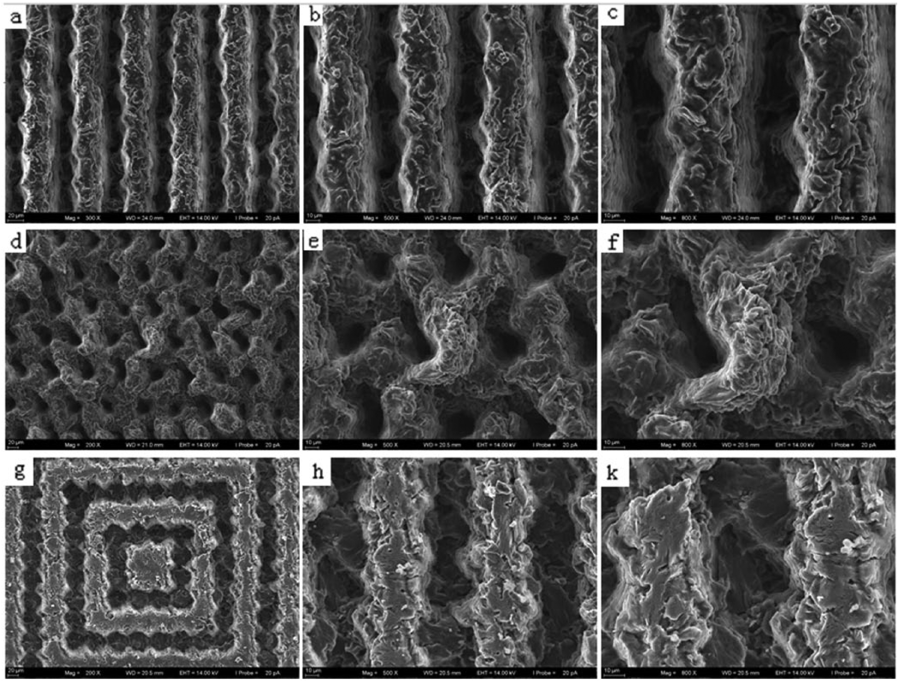
Scanning electron microscope images of pyrolytic carbon by laser etching.
Figure 2 shows SEM images of ZnO film growing on the PyC surface. Photo 2(a) to (c) show SEM images of rod-like ZnO film. Figure 2(a) is a SEM image of ZnO film amplified 5000 times: dense rod-like ZnO film is formed on the PyC surface. Figure 2(b) is a SEM image of ZnO film amplified 10,000 times: the growth of dense rod-like ZnO film is disordered and disorientated. Figure 2(c) is a SEM image of ZnO film amplified 20,000 times: dense rod-like ZnO is hexagonal and hollow, the side length of rod-like hexagonal ZnO is 100–200 nm. Figure 2(d) to (f) show SEM images of ball-like ZnO film. Figure 2(d) is a SEM image of ZnO film amplified 200 times: dense ball-like ZnO film is formed on the PyC surface and gathers together. Figure 2(e) is a SEM image of ZnO film amplified 2000 times: the ball-like ZnO film is not solid but dandelion-shaped. Figure 2(f) is a SEM image of ZnO film amplified 5000 times: cotton-like fibers extend from the core of every single ZnO ball.
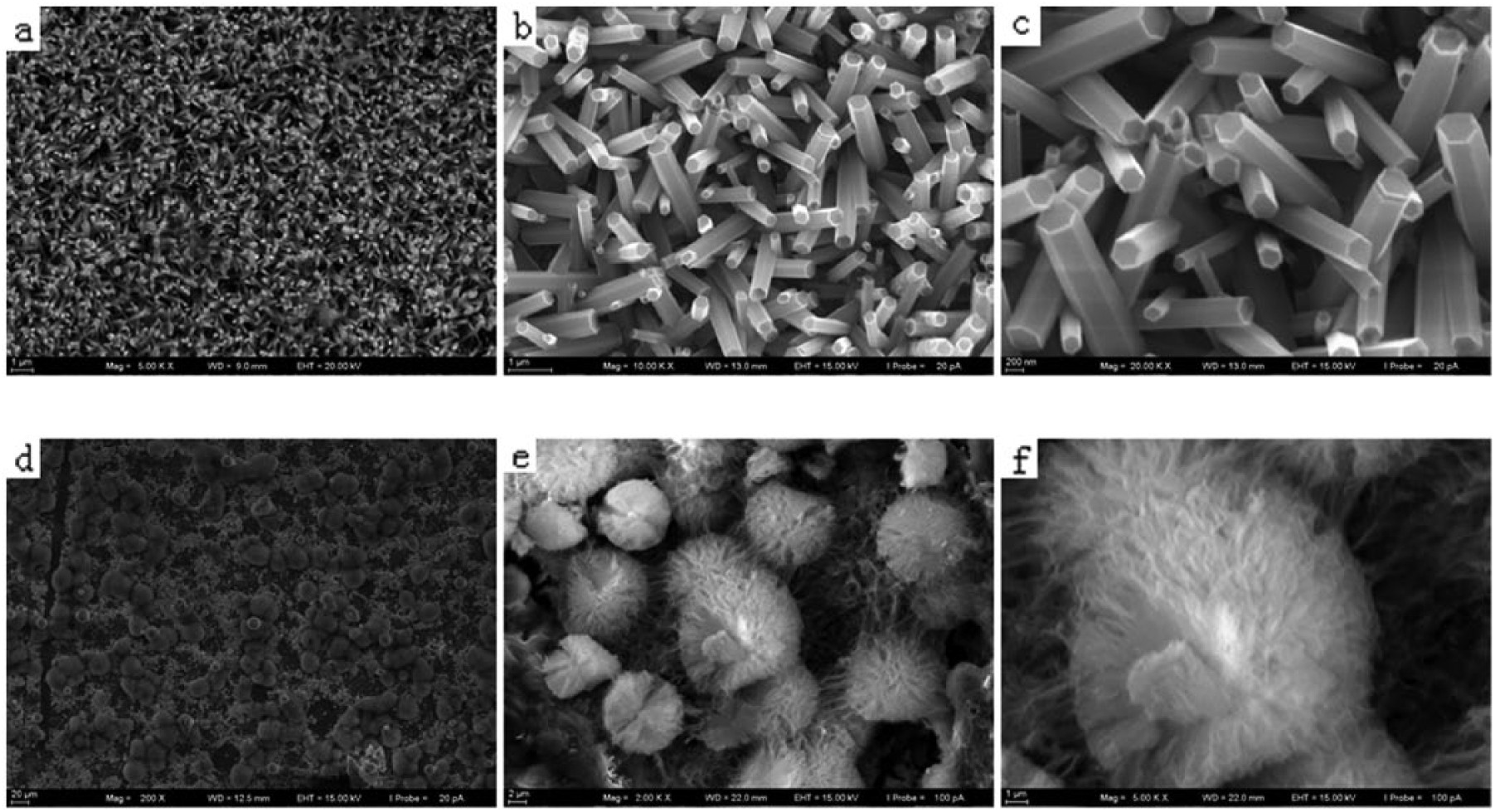
Scanning electron microscope images of ZnO film growing on a pyrolytic carbon surface.
Figure 3 shows SEM images of the PyC surface by electrospinning. Figure 3(a) to (c) show SEM images of PVP nanofiber film. Figure 3(a) is a SEM image of PVP fiber film amplified 1000 times: compact PVP fiber film is formed on the PyC surface and the combined fibers are disorganized and disordered. Figure 3(b) is a SEM image of PVP fiber film amplified 5000 times: the criss-crossed PVP fibers form a unique network structure and have high porosity and high surface area. Figure 3(c) is a SEM image of PVP fiber film amplified 10,000 times: PVP fiber film is combined fibers of various diameters and for a single fiber the diameter is even. Figure 3(d) to (f) show SEM images of PVP/TiO2 complex nanofiber film. Figure 3(d) is a SEM image of PVP/TiO2 fiber film amplified 1000 times: compact PVP/TiO2 complex nanofiber film is formed on the PyC surface, the combined complex nanofiber film is disorganized and disordered and TiO2 particles are distributed in the film. Figure 3(e) is a SEM image of PVP/TiO2 complex nanofiber film amplified 5000 times: the distribution of TiO2 particles in PVP fiber forms PVP/TiO2 complex nanofiber film. Figure 3(f) is a SEM image of PVP/TiO2 complex nanofiber film amplified 10,000 times: the criss-crossed PVP/TiO2 complex nanofibers form a unique network structure, have high porosity and high surface area, and form papilla-like structures in the film.
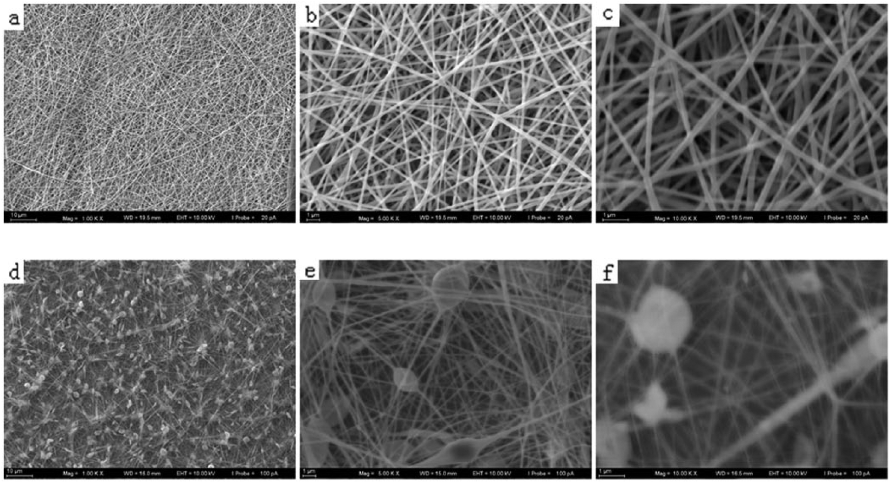
Scanning electron microscope images of a pyrolytic carbon surface by electrospinning.
Characterization of contact angle
The size of contact angle reflects the amount of PyC surface energy. The larger the contact angle is, the smaller the surface energy is, and the stronger the hydrophobicity is. Figure 4(a) to (h) show the size of corresponding contact angle of different PyC surface structures. Figure 4(a) shows that the corresponding contact angle of grating pair structure is 154°, which is greater than the critical 150° of the super-hydrophobic contact angle. Figure 4(b) shows that the corresponding contact angle of microhole array structure is 153°, which is greater than the critical 150° of the super-hydrophobic contact angle. Figure 4(c) shows that the corresponding contact angle of helix structure is 152°, which is greater than the critical 150° of the super-hydrophobic contact angle. Figure 4(d) shows that the corresponding contact angle of rod-like ZnO film is 158°, which is greater than the critical 150° of the super-hydrophobic contact angle. Figure 4(e) shows that the corresponding contact angle of ball-like ZnO film is 160°, which is greater than the critical 150° of the super-hydrophobic contact angle. Figure 4(f) shows that the corresponding contact angle of PVP fiber film is 156°, which is greater than the critical 150° of the super-hydrophobic contact angle. Figure 4(g) shows that the corresponding contact angle of PVP/TiO2 complex nanofiber film is 158°, which is greater than the critical 150° of the super-hydrophobic contact angle. Figure 4(h) shows that the corresponding contact angle of the smooth PyC surface is 70°, which is less than the critical 150° of the super-hydrophobic contact angle. Hence, PyC is a kind of hydrophilic material but it is super-hydrophobic through constructing microstructures on the PyC surface and then silanizing.
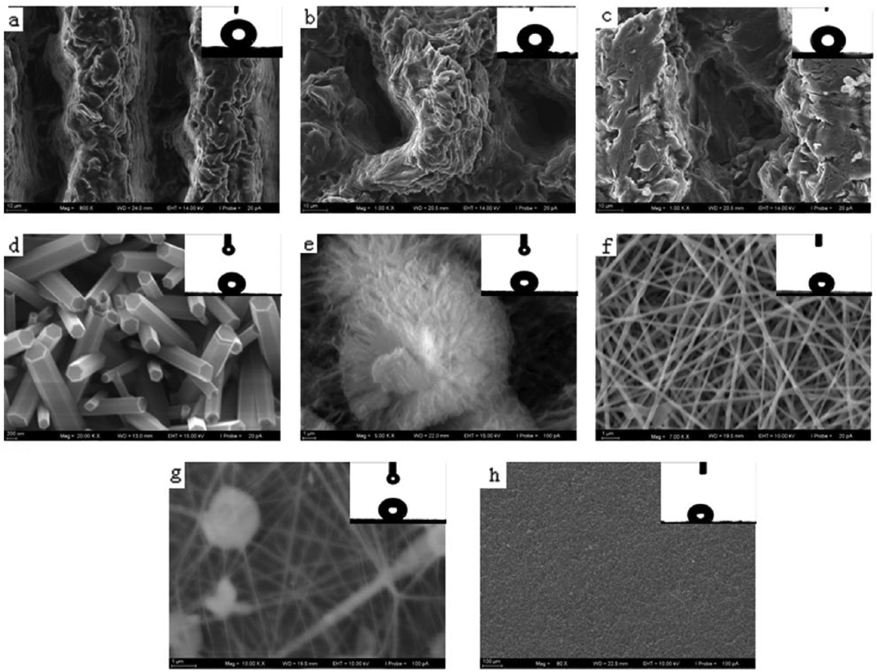
Scanning electron microscope images of contact angles on a pyrolytic carbon surface.
Mechanism analysis
Low surface energy and high roughness determines that the solid surface is super-hydrophobic. The liquid–air contact percentage on the PyC surface is improved and the liquid–solid contact percentage on the PyC surface is lowered by constructing different microstructures on it. Meanwhile, silanizing PyC surface achieves low surface energy. Hence, rough PyC surface and low surface energy make PyC possess super-hydrophobicity, which reduces blood flow resistance. The adhesion of platelets on a valve surface reduces subsequently and finally inhibits thrombus.
The hydrophobic surface is subject to its roughness, which shall form a certain amount of liquid–vapor interface, so the surface is heterogeneous, with the contact angle of a coarse surface shown in the formula

where
After silanization treatment of fiber film, the surface is improved in hydrophobicity. Since drops cannot fully and completely fill the fiber meshes, some air is retained beneath the liquid drops. According to formula (1), the condition of fiber film for generation of hydrophobicity is deduced as
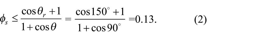
Figure 4 shows that fiber film is actually accumulated by interwoven nanofibers, forming porous netted structures; when the contact area of the solid part of fibers with liquid is less than 13% of the total area, super-hydrophobicity thus occurs.6–10
Conclusions
Microstructure formed respectively by nanoseconds laser etching, hydrothermal and electrospinning method increases the surface roughness and forms periodical microstructure.
Infiltration experiments on rough and smooth PyC surfaces have found that a rough PyC surface with microstructure is super-hydrophobic and has more than 150° contact angle, which decreases blood flow resistance and inhibits thrombus.
Electrostatic spinning technology is capable of texturing porous network film with a heterogeneous structure, whereas meshes beneath liquid drops retain air, leading to super-hydrophobicity. Manufacture of super-hydrophobic surfaces via electrostatic spinning technology can be widely applied to surfaces of other materials.
Footnotes
Declaration of Conflicting Interests
The author(s) declared no potential conflicts of interest with respect to the research, authorship, and/or publication of this article.
Funding
The author(s) disclosed receipt of the following financial support for the research, authorship, and/or publication of this article: This work was supported by the Colleges Natural Science Foundation of Jiangsu (grant number 15KJA430003), the Production and Research of Jiangsu University of Technology (grant number KYH16033) and Changzhou High-tech Key Laboratory (grant number CM20153001).