
Abstract

INTRODUCTION
In recent years, the pace of scientific progress in healthcare has increased dramatically. New procedures and equipment born of this progress have substantively altered organizational and operational relationships in healthcare laboratories. Among the advancements that have driven this change is the evolution and incorporation of robotics. Today, laboratories must be designed for the efficient and economical inclusion of equipment; a core laboratory concept, rather than procedurally-based departments.
There exist many laboratories which require renovation or replacement to regain their status as a profit center. Whether this up-dating is accomplished incrementally or all at one time, the suitability of traditional laboratory design must be questioned. Beyond the basic floor plan, a myriad of code issues, requisite demands on utilities and structure, and a fundamental need for flexibility are implicit in the decision to incorporate an equipment based core laboratory design.
BASICS OF THE DESIGN
The best starting place for the design of a laboratory is to thoroughly investigate the relationships between and among the various components (e.g. equipment, departments, procedures, personnel, patients, etc.) of the laboratory. Graphically, this can be accomplished with the use of a bubble diagram. (figure 1)
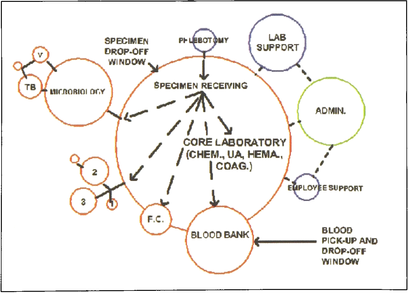
Bubble Diagram: Examining the laboratory in this manner may illustrate operational relationships that properly exploited could increase efficiency by sharing spaces and talents.
After these relationships have been determined, the space requirements for each component must be calculated. Historically, equations based on the number of full time equivalents (FTE's), the number of beds in a facility, or the number of procedures performed were used to determine square foot requirements. These equations are no longer accurate due to the increased efficiency of today's technologies and a move to outpatient based services.
The best method of determining space requirements is to list present equipment, equipment planned for the near future, the workstations required, and required clearances. These can then be sketched in a rough manner to give a fairly accurate assessment of each laboratory's area. Flexibility, with some “soft” space (areas that have other uses, but can be converted to lab space if necessary) should be incorporated into this estimate. There exists one major technology - created caveat to be observed in arriving at this estimate. Core lab areas and robotic lines have specific space requirements due to the dimensions of equipment. In developing a laboratory size estimate, remember that regardless of how many tests these machines perform, their space requirements remain the same.
The core concept can save space in the overall laboratory design. This can be attributed to several factors. Components that were repeated for each individual laboratory can be shared in one space. Cross-training of technologists coupled with a more efficient arrangement of equipment can enable fewer people to do the same amount of testing in a timely manner. In the near future, many analyzers will be consolidated to provide faster and more comprehensive testing on a single piece of equipment, saving even more space and making departmental segregation even more obsolete.
Areas for stat testing may no longer be required. Many laboratory managers have found that by grouping analyzers, especially those that are utilized by lightly staffed shifts, efficiency is increased so much that all testing is done in a stat time frame. This also eliminates redundancy of equipment required to support separate stat and routine functions. Ports in robotic lines can be added to place stats ahead of routine testing at different locations in the line, if required. Finally, through all these efficiencies, the core laboratory concept even saves space by requiring fewer walls and door swings.
After specific relationships have been defined and a rough size estimate has been developed, a block diagram can be generated. The blocks represent each actual laboratory space placed into the floor plan of the area being constructed or renovated. The block diagram may be utilized to determine the flow or movement of specimens, people, supplies and waste into and out of the laboratory space. The next step is to develop the specifics of the core robotic area.
THE CORE OR ROBOTIC DESIGN
The major components of a typical clinical laboratory can be broken into two categories:
“Manual” testing areas - areas that employ smaller, more specialized analyzers, some manual procedures, and other countertop oriented practices.
“Automated” testing areas - areas that house large analyzers or robotics.
There is no need for separate rooms for any of the lab components other than those that require biosafety isolation or specialized ventilation.
The orientation of the various phases of laboratory testing is important to maximize efficiency (Figure 2)
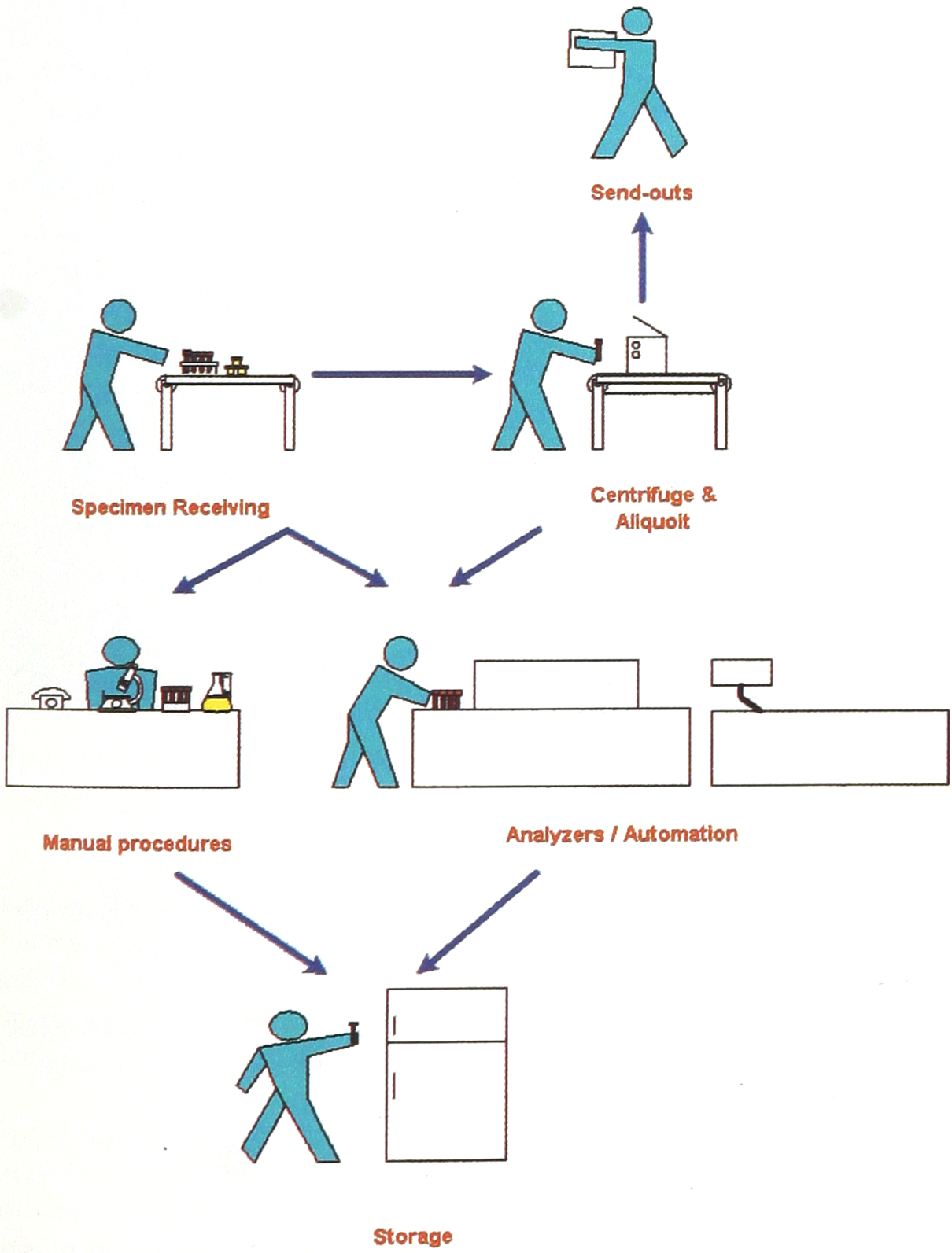
TESTING ORIENTATION
The apex of the lab should be the specimen receiving and processing areas. All samples should be filtered through this area for triage and data entry, bar coding, and preparation. From here a direct, unobstructed line to the testing areas for whole blood and separated samples should be maintained.
Maintaining the most direct and logical movement for specimens is usually best for equipment and personnel. Plan easy access to refrigeration, manual areas, and instrument backs. It is important to keep the analyzers that are utilized by lightly staffed shifts as close to each other as possible, and close to the receiving and preparation area.
The transition from analysis to storage should be smooth and efficient. This is essential not only for the placement of samples into storage, but also for the retrieval of samples for subsequent testing. A computerized specimen retrieval system is a major time saver, some models even attaching directly to robotic systems.
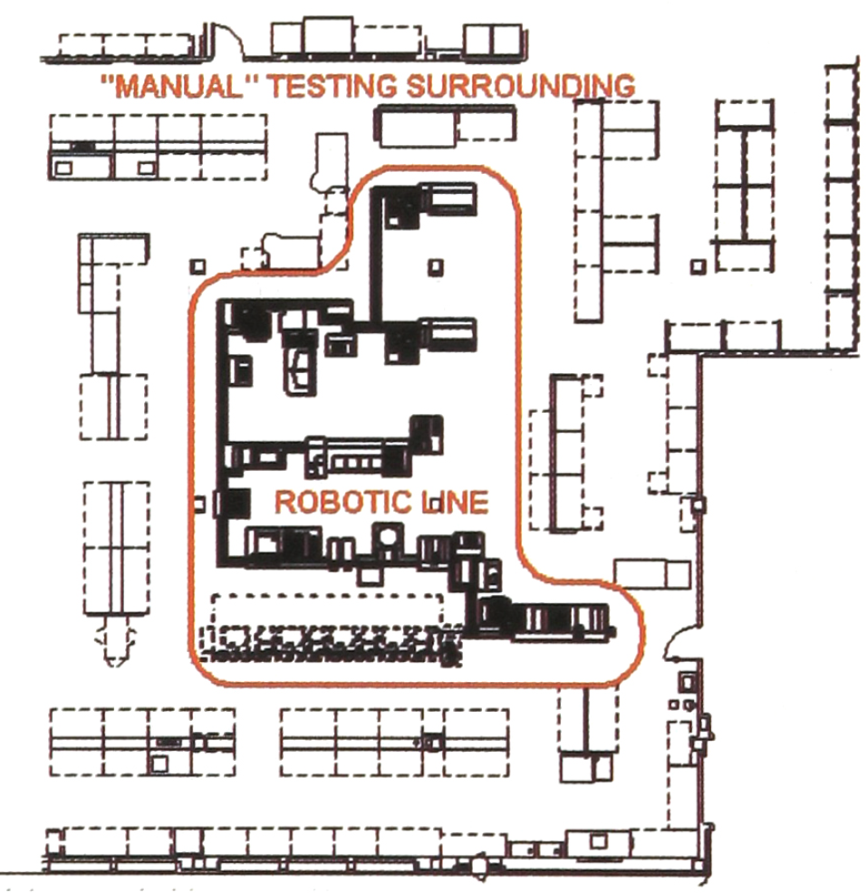
The robotic laboratory is essentially an open, equipment based core laboratory with major analyzers connected by a robotic line or conveyer. The orientation of robotic laboratories is thus the same as other core laboratories, the difference being the requirements of the robotic conveyer line. In the course of designing a laboratory, it is prudent to consider directing the architect to modify the drawings of the core laboratory area to include robotics even if such equipment is not to be included in initial construction. This practice can be beneficial in illustrating how robotic equipment may, in the future, fit into a laboratory floor plan and how such equipment may enhance the operation of the lab (Figures 3 & 4).
It is important for laboratory architects to work with robotic manufacturers so that the physical requirements of such equipment are satisfied.
SPECIFICS THAT AFFECTTHE LAB DESIGN
Flexibility is very important to allow for the normal, frequent changes in testing and equipment that is so typical in laboratories. It has been documented that most labs will undergo some sort of change every three months, on average. Designing casework and utilities to flexibly adapt imparts the ability to reconfigure the laboratory to meet changing demands. A majority of recently designed labs have opted for a core arrangement with the recognition that a robotic line, whether with “work cells” or a full line will be added in the near future. An additional benefit of planning for the phased update of a laboratory is the subsequent phasing of budgets,
Casework is of primary importance when designing a laboratory to flexibly adapt to change. There are many casework manufacturers that offer varying degrees of flexibility and cost. Manufacturers are pleased to explain their products and offer tours of laboratories that have installed them. Manufacturers also often offer the opportunity for a hands-on product demonstration at a potential customer's own laboratory. To achieve a safe, efficient and truly flexible result, It is paramount that lab architects and engineers be consulted about casework product choices early in the planning process to ensure that casework product specifications will properly integrate with other parameters of the design.
Flexibility in the laboratory can not be realized without flexibility in the laboratory's utilities. Lab utilities include air, water, drainage, electricity, and telecommunications. Air (ventilation) is one of the most visible and expensive components of the laboratory. It must be designed correctly from the start to ensure an environment that is comfortable for personnel and acceptable for equipment. There are guidelines for temperature and humidity that must be met in the design. The ranges recommended for laboratories are illustrated in the following table:
ENVIRONMENTAL DESIGN FACTORS - Laboratory Work Areas
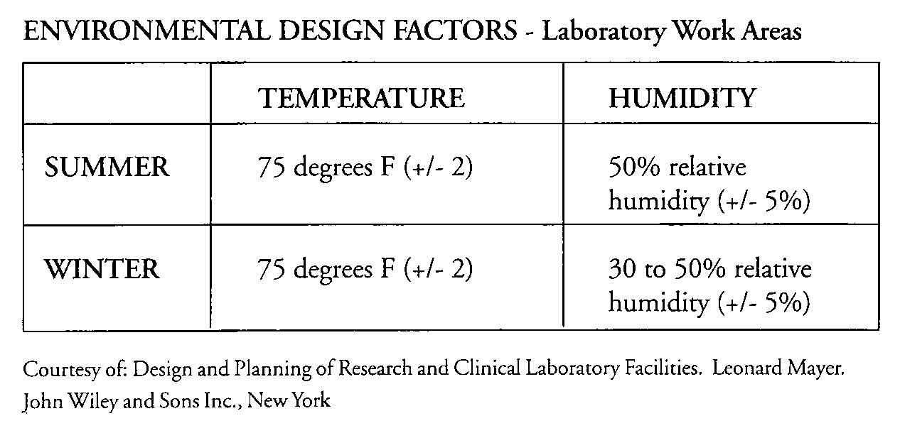
Courtesy of: Design and Planning of Research and Clinical Laboratory Facilities. Leonard Mayer. John Wiley and Sons Inc., New York
The number of air changes per hour is key to maintaining comfort. Changes per hour may range from six to twenty depending on local requirements and the amount of possible aerosol contamination that exists in a particular laboratory. This should be discussed with the laboratory architect, engineer and facility infection control officers.
To incorporate flexibility in the laboratory ventilation system, the potential of adding or subtracting equipment such as analyzers and hoods must be weighed. Consideration should be given to a variable air volume system to reduce costs and to allow for additions. The actual construction of the ductwork and placement of supply and exhaust vents should be such to allow changes with minimal disruption. Some ways to attain this are to use exposed ductwork, flexible ductwork, or ceilings that can be easily opened (suspended type) to adjust the location of vents. Elephant trunks are a type of flexible ductwork that can be bent, moved around and directed where needed. While elephant trunk ductwork has yet to become popular in clinical laboratories, it is a viable solution to flexibility needs in that setting.
It is also possible to design water and drainage systems to flexibly adapt to changing needs. Water pipes usually originate in the ceiling space of a laboratory, making them accessible due to open or easily removed (suspended) ceiling plans. It is not necessary to place descending pipes inside a wall as long as they are supported appropriately. Locating plumbing outside of walls markedly increases flexibility but requires some creativity to create a pleasing aesthetic environment. Incorporating some flexibility into the design of drainage systems can be more challenging. Normally drains go down, either into plumbing or trenches in the floors or into the ceiling space of the floor below. Constructing a series of drains in a grid pattern makes it possible to move equipment and casework with sinks to different locations without being constrained by drain locations or construction costs. Another more unusual and more maintenance intensive solution is to incorporate pump systems that pump laboratory waste up into plumbing in the ceiling space.
Achieving flexibility in the design of lab electrical and telecommunication systems is easily accomplished. Wiring should be kept in suspended and organized cable trays with outlets, whether electrical, data, or telephone, distributed every few feet along casework and walls. The main wiring for island casework and for equipment can come from power poles that may be easily relocated. Utilizing landscape panels (flexible, partial height walls often used in office situations) can afford the means to have outlets in equipment areas while absorbing sound, and protecting wiring and plumbing from becoming tripping hazards.
Lighting systems are often overlooked when designing flexibility into laboratory systems. Shadows, glare and low illumination levels may result from improperly designed lighting, problems that can be further compounded by procedural changes. A well designed direct/indirect lighting system (25% of the light goes up toward the ceiling and 75% of the light goes down) can provide even light with little glare or contrast (those bright spots on computer screens). Task lighting is a necessity for procedures that require close work. Incorporate task lighting that is plugged in rather than hard wired to allow it to be moved if required. Consider lighting that is mounted to upper cabinets, preferably on a flexible arm that allows easy movement for specific tasks and tastes, while keeping countertops clear.
Major safety issues that must be addressed in a laboratory design are fire and life safety, biohazard safety, and ergonomics. Fire and life safety codes are crafted on the underlying premise that people must be able to evacuate the lab safely and quickly in the event of a fire. The lab design must comply with code-specified clearances for doorways and corridors. Clearances around analyzers and robotic equipment must also meet code requirements. In addition to egress clearances required by fire codes, the lab design must include extra clearance for handicapped individuals, such as that as specified by the Americans with Disability Act(ADA).
Biohazard safety must be addressed in areas that are working with agents that are known or suspected of causing disease. This concern is commonly encountered in labs working with bacteria, viruses, and fungus. All laboratories that deal with human fluids are considered biohazard safety level 2 (BSL 2). According to code, these laboratories may not be open to areas frequented by patients or visitors to protect them from possible contamination. Code also specifies that space must be provided in the lab for handwash sinks, emergency stations and emergency showers.
Ergonomics, while not regulated by code, are important in the reduction of on-the-job injuries and sick days. Lifting is a classic and frequently encountered ergonomic issue, but in laboratories, the effects of long term standing and white noise occur as often. Resilient floor coverings and resilient mats placed at work stations can alleviate many systems associated with long term standing. The headaches and illness associated with white noise, the constant, irritating background sound generated by equipment, can be mitigated by utilizing finishes (ceiling tiles, wall coverings and floor coverings) that absorb sound. The landscape panels previously discussed in association with the distribution of wiring may also be very useful for eliminating white noise at its source.
OTHER ROBOTIC AND EQUIPMENT DEMANDS ON THE FACILITY
Concentrating many pieces of equipment into a compressed area creates some unique problems for laboratory designers. Many analyzers weigh between 700 and 1200 pounds. When several such analyzers, along with robotic components and operators are located in a small area, concerns about the building's structural ability to support such weight are created. Structural engineers analyze these concerns in term of “point loads”, quantitatively determining whether each part of the building's structure can withstand the weight loading that it will be subjected to.

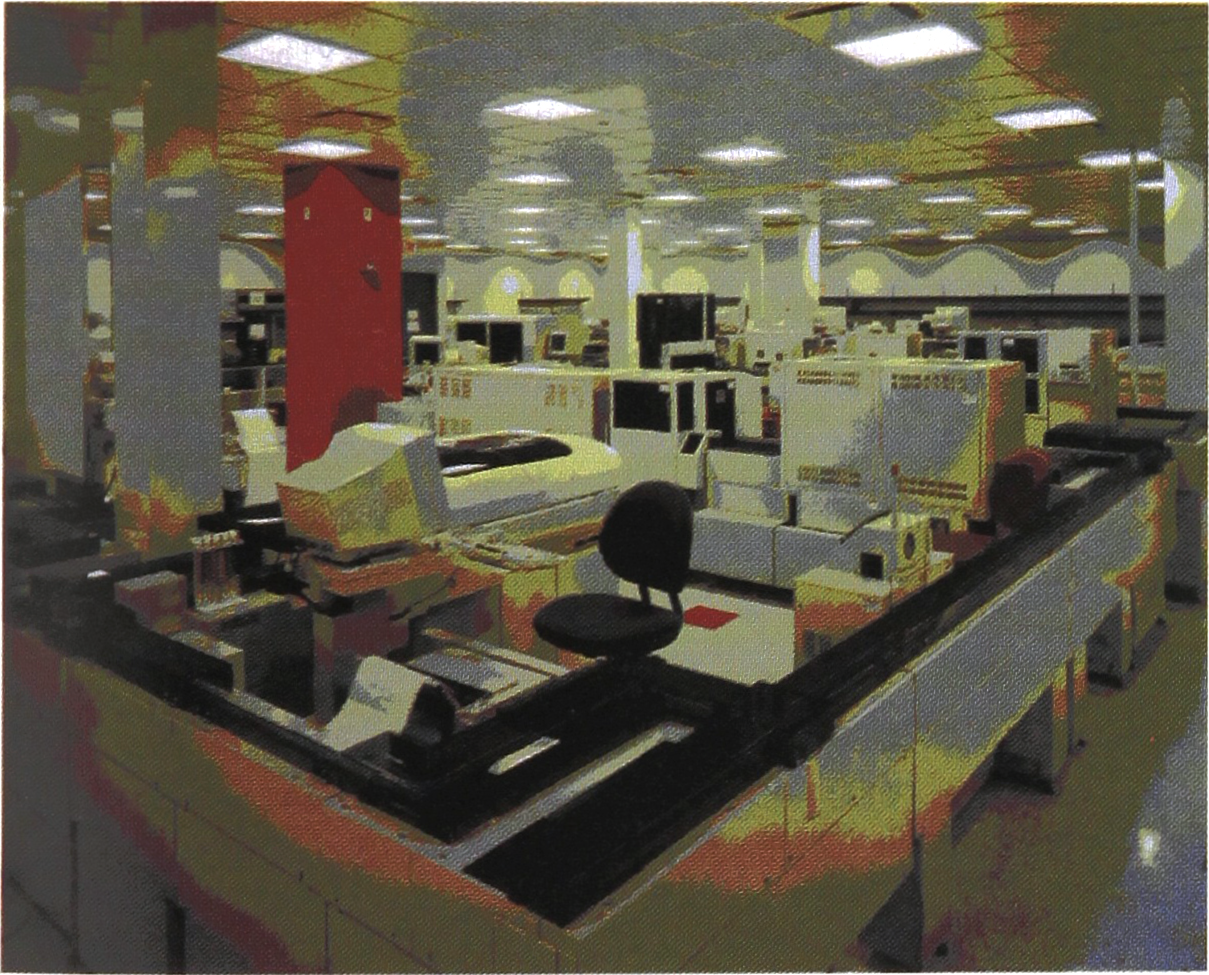
Northshore Robotic Laboratory - An efficient and pleasing laboratory environment
Some equipment may be adversely affected by discrepancies in the level of flooring. Leveling the floor can be a problem in an older building that has settled or if contractors have sloped the floor to a drain. The operation of equipment and robotic conveyers can be disrupted if the floor slope is beyond manufacturer's specifications.
The concentration of analyzers also affects heat loading. Excessive heat created by equipment grouped in small areas can be uncomfortable for people and hard on equipment. There should be exhaust intakes located in these areas to maintain comfort levels in the immediate area and in the balance of the lab. In extreme cases, flexible ducts can be run directly from analyzers to the exhaust system.
An often encountered problem with moving laboratories, especially those with large analyzers, is moving equipment through buildings to their final destination. Corridors are large enough in most buildings to not be a problem, but in older buildings and in buildings with non health care classifications, tight spots may be encountered when moving large pieces of equipment near columns and around corners. Elevators that are too small or haven't the weight capacity for large analyzers may also be a problem. Finally, each doorway that equipment must move through on its way to the lab must be checked for size. When measuring the size of analyzers, remember to include any protrusions on the front, back or sides as such interferences can make passage through an under-sized door impossible. One method for checking potential moving clearance problems before they happen is to have the lab architect make a “paperdoll” of your analyzer (in plan view) at the same scale as the floor plans of your facility. Take this silhouette and move it down each corridor, through each door, into each elevator, and around each corner to its final destination in the lab. This process will quickly reveal potential problem areas and allow an alternate route to be planned if necessary.
CONCLUSION
The priorities and problems in laboratory planning and design are now driven by rapidly evolving technological advancement. Many traditionally designed existing laboratories are struggling to adapt to this paradigm shift. It is imperative to design core or robotic laboratories with an emphasis on equipment, as today and tomorrow, it will be the efficient inclusion of equipment that will establish a laboratory as the profit center it must be to succeed.