
Abstract

Introduction
The use of piezoelectric drop-on-demand ink-jet printing technology (MicroJet Technology) for microdispensing fluids has broad applicability for use in biochemical processes.
With MicroJet Technology, spheres of fluid with diameters of 25–100μm can be produced at rates of 0–8,000 per second. Multiple MicroJet devices can be used to print multiple fluids (probes, reagents, sample, etc.), similar to the way ink-jet printers print four colored inks to make a color print. The ability to dispense 25–100μm droplets equates to a single droplet volume resolution of 10pl to 0.5nl. [Note that this range represents the design space of dispensing systems, not the operating space of a specific system.] Reducing volumes from the 1μm range to the 1nl range would reduce the usage/cost of rare reagents (e.g., cells, cellular produce, cellular extracts, etc.) by three orders of magnitude. In addition, by reducing the size of a single biochemical reaction/test, many reactions/tests could be processed either in parallel or in rapid succession, and the small size of these “biochemical reaction arrays” would make implementation of automated systems easier. This would increase throughput drastically, again lowering cost. A brief background on MicroJet Technology follows, along with a discussion of two potential applications: high throughput drug discovery and DNA diagnostics.
Background
In a piezoelectric drop-on-demand ink-jet device, a volumetric change in the fluid is induced by the application of a voltage pulse to a piezoelectric material that is coupled to the fluid. This volumetric change causes pressure/velocity transients to occur in the fluid and these are directed so as to produce a drop that issues from an orifice. 1 Figure 1 shows a MicroFab drop-on-demand type ink-jet device generating 50μm diameter drops of ethylene glycol from a device with a 50μm orifice at 2,000 per second. One of the characteristics of ink-jet printing technology that makes it attractive as a precision fluid microdispensing technology is the reproducibility of the process.
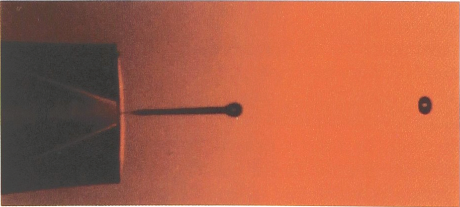
Drop-on-demand type ink-jet device generating 50μm diameter drops at 2kHz
The image of droplets shown in Figure 1 was made by illuminating the droplets with an LED that was pulsed at the droplet generation frequency, 2kHz. The exposure time of the camera was ∼1 second, so that the images represent 2000 events superimposed on each other. The reproducibility of the process results in an extremely clear image of the droplets, making it appear to be a high speed photograph.
To illustrate the degree to which ink-jet microdispensing could further reduce the size/volume scales, Figure 2 shows ink printed on the bottom of a 96 well plate in the form of characters. The 60μm drops used produce 100μm spots and individual spots are visible in the blow-up of the T at lower right of the image.
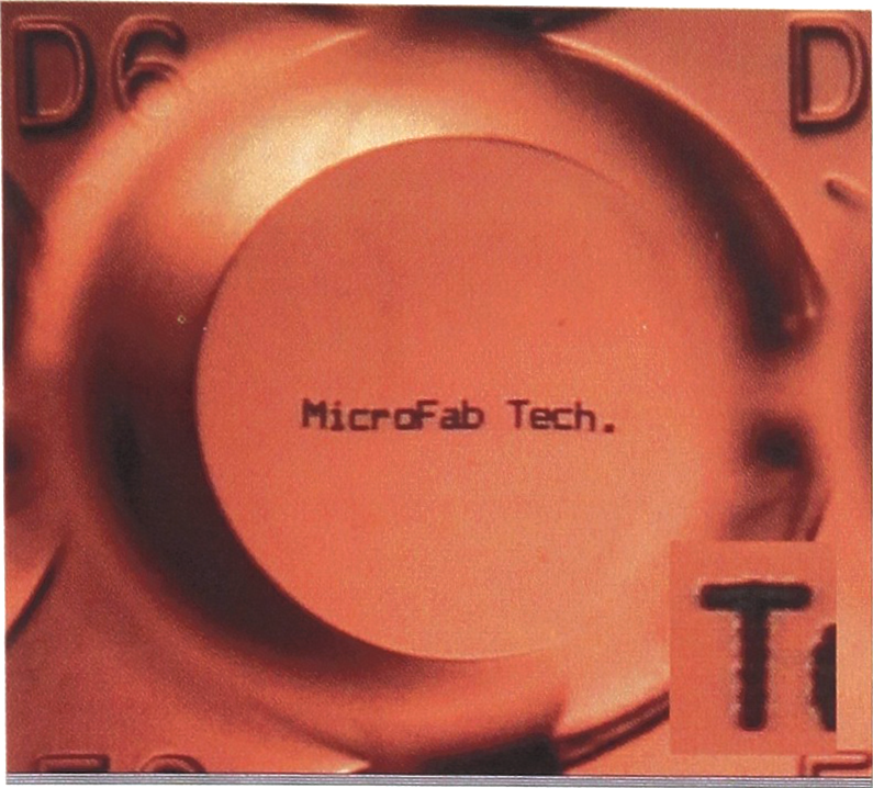
Ink printed onto the bottom of a 96 well plate to form characters, illustrating the resolution of ink-jet dispensing
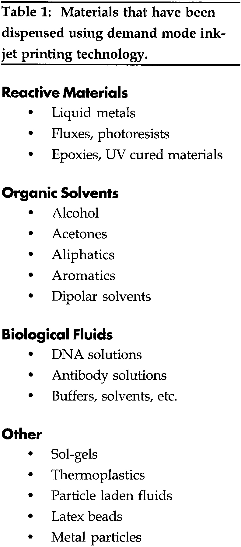
Achieving the ultimate potential of ink-jet microdispensing will depend on resolving a number of issues, material compatibility being one of the most important. This is especially the case for chemical synthesis, where a wide range of materials is used. Each ink-jet printhead/dispensing system would have to be designed specifically for the materials that it is expected to dispense. To illustrate range of materials that can be dispensed, Table 1 shows the types of materials that MicroFab has successfully dispensed. Some of these materials are components of both water-based and solvent-based inks used in our array printhead development efforts. The others are a result of our efforts to apply ink-jet dispensing to electronics manufacturing processes, 2 micro-optical element fabrication, 3 laser surgical procedures, 4 and medical diagnostics manufacturing.
Materials that have been dispensed using demand mode ink-jet printing technology.
Examples of the printing of these materials listed in Table 1 are shown in the adjacent figures. Figure 3 shows features etched in a polymer by dispensing acetone with ink-jet technology. Figure 4 shows an array of thermoplastic microlenses printed with ink-jet technology.
500μm diameter features etched in a polymer by dispensing acetone using ink-jet technology
40μm thermoplastic lenses printed on 50μm centers using ink-jet technology
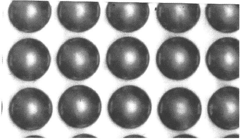
Figure 5 shows solder bumps that were created by ink-jet dispensing of molten solder onto the silicon substrate.
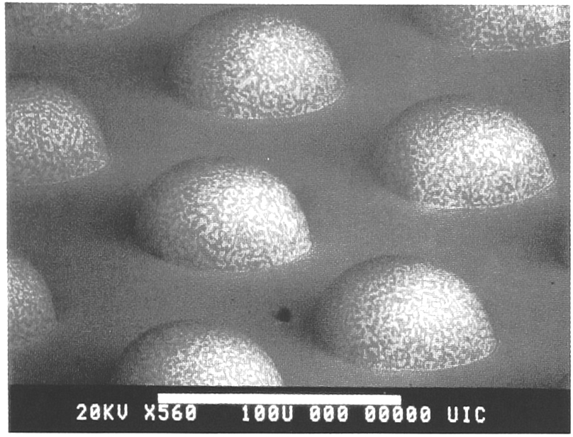
70μm solder bumps on metallized silicon, deposited using ink-jet technology
As part of a National Institute of Standards and Technologies Advanced Technology Program grant to the Genosensor Consortium, MicroFab has developed an ink-jet based oligonucleotide array printer. 5 Eight modular dispensing units, each with an integral 500μl reservoir, can be installed on the printer at a time. Each of the eight dispensers can be addressed by the drive and control electronics via a PC, but only one of the eight can be active at a time.
The modular dispensing modules are mounted on a plate so that groups of eight dispensers can be changed easily while maintaining their alignment. Figure 6 shows a schematic of the system.
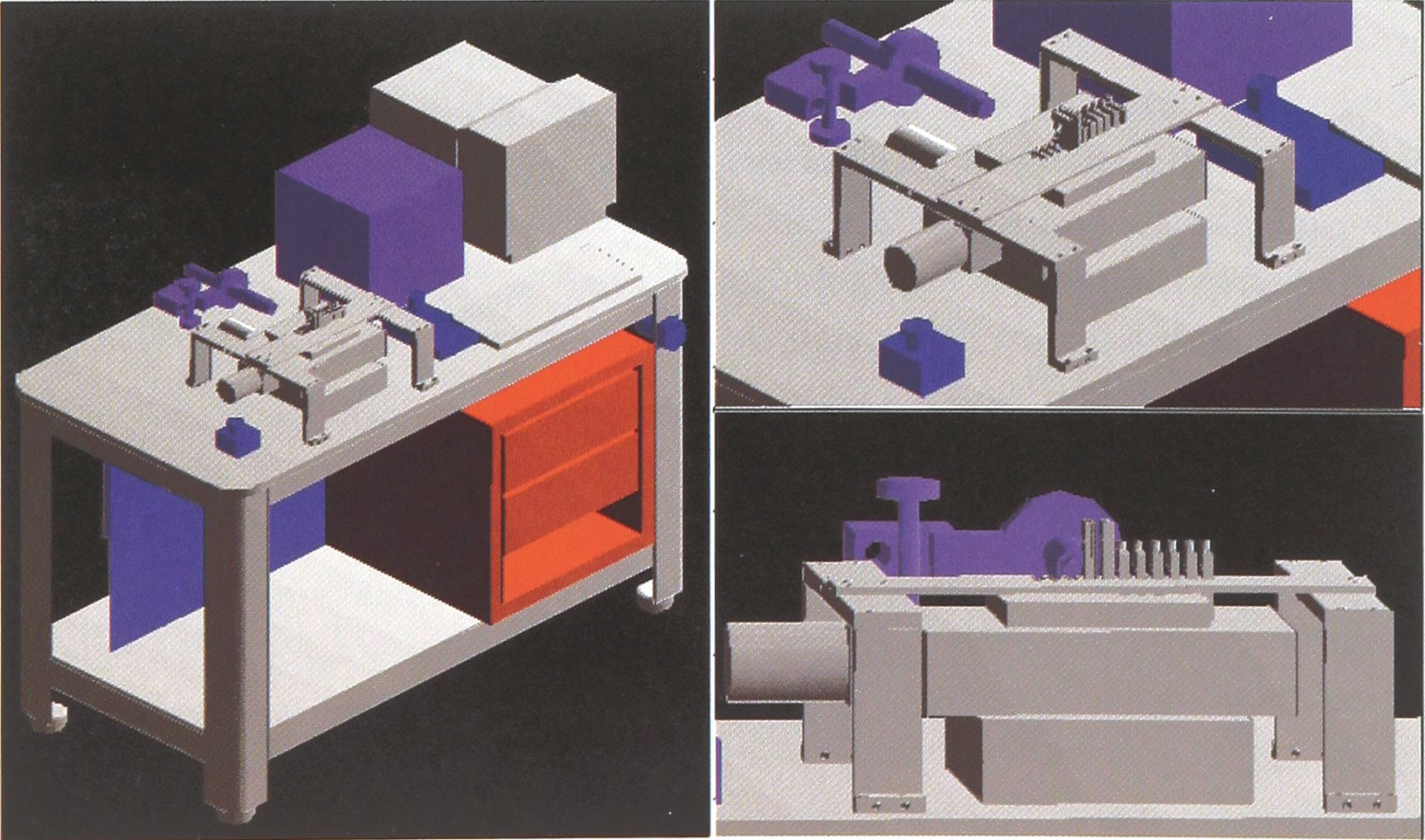
Eight fluid oligonucleotide probe array printer used in the Genosensor Consortium research
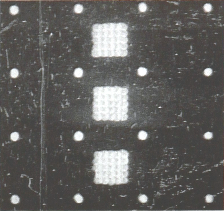
To date, we have successfully printed oligonucleotide probe arrays containing thirteen different probes and have made arrays using sixteen different dispensing devices (all using the same fluid, a fluorescent ink). In addition, we have fabricated arrays of dye spots of different sizes and spacings to support the imaging development efforts.
An example of this work is shown in Figure 7. Here, eight different concentrations of CY5 fluorescent dye in DMSO were printed onto a polypropylene sheet in the form of ∼100μm spots on 300μm centers. These were then imaged using a cooled CCD camera and evanescent wave excitation. The results indicated a four order of magnitude range of detectability.
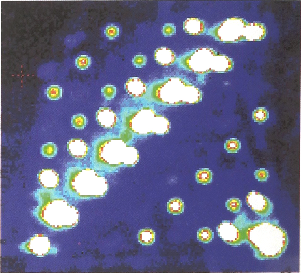
Detection sensitivity experiment using eight different concentrations of CY5 printed as 100μm diameter spots on 300μm centers
Figure 8 shows an experiment where two dyes with different absorption/emission spectra have been printed onto polypropylene film in interleaved arrays of 100μm diameter spots on 300μm centers. These were also imaged using a cooled CCD camera and evanescent wave excitation. These results indicated no optical interaction between the two dyes when excited at the proper frequencies. [Figures 7 and 8 courtesy of John Silzel, Beckman Instruments).
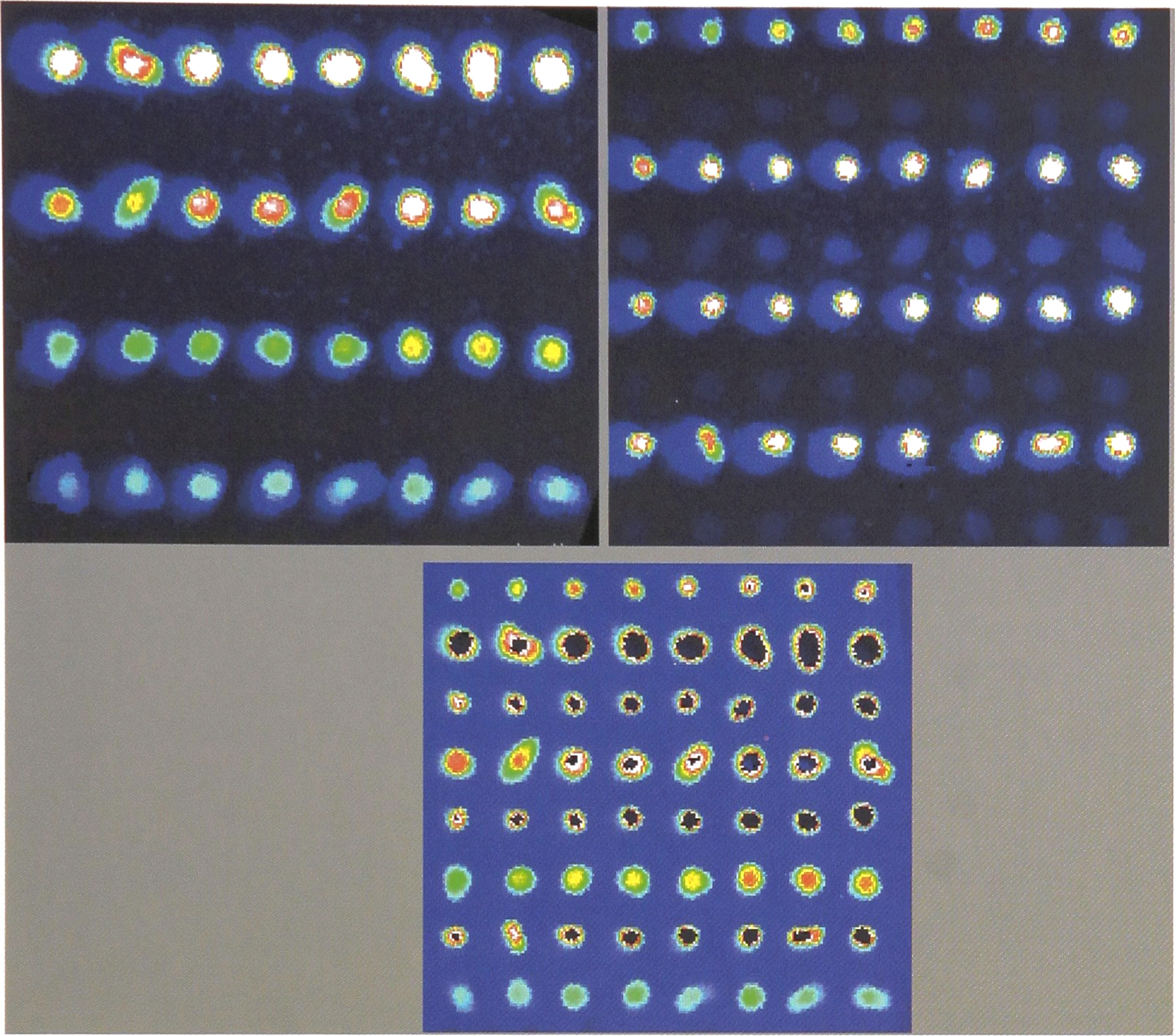
Detection system evaluation with two dyes printed as 100μm diameter spots on 300μm centers with different absorption/emission spectra. Top left, excitation of one dye, top right, excitation of second dye, bottom, computer composite of the two images