
Abstract
Flexible automation systems provide the needed adaptability to serve shorter-term projects and specialty applications in biochemical analysis. A low-cost selective compliant articulated robotic arm designed for liquid spillage avoidance is developed here. In the vertical-plane robotic arm movement test, the signals from an inertial measurement unit (IMU) and accelerometer were able to sense collisions. In the horizontal movement test, however, only the signals from the IMU enabled collision to be detected. Using a calculation method developed, it was possible to chart the regions where the obstacle was likely to be located when a collision occurred. The low cost of the IMU and its easy incorporation into the robotic arm offer the potential to meet the pressures of lowering operating costs, apply laboratory automation in resource-limited venues, and obviate human intervention in response to sudden disease outbreaks.
Introduction
There have been keen efforts to apply automation and high-throughput techniques in various development laboratories to serve diverse workflows. 1 These include reactor-based systems that are useful for applications in synthesis, screening, and process optimization,2-6 as well as laboratory automation in clinical testing and diagnostics to increase process efficiency and standardization, shorten lab process cycle time, and enhance quality assurance of experimental data.7,8 Traditionally, automation has been applied to dedicated workflows, although there is increasing need to devise more flexible automation systems to serve shorter-term projects and specialty applications. Robotic automation systems are suited for this, as they can operate on a stand-alone basis or be integrated to form work cells.9-11 In addition, the robotic system can be customized or personalized according to needs and budget. This has been done to meet the pressures to lower operating costs, 12 apply laboratory automation in resource-limited venues, 13 or obviate human intervention in response to sudden disease outbreaks. 14
The most important component of a robotic system is its arm or manipulator. It is seldom appreciated that there are two major types of robotic arms in use (see Fig. 1 ). Cartesian (gantry) robots work from an overhead grid, and they have a work envelope that is rectangular and dictated by the overhead grid. The Cartesian-style robot is capable of X, Y, Z linear directional movements. They are relatively easy to program and ideal for applications that require movements such as straight-line insertions. Alternatively, the Selective Compliant Assembly Robot Arm (SCARA) provides a circular work envelope. Using a series of rotational movements at the joints, it can be made to provide a broad range of motions, thus allowing for added flexibility. Additionally, it has a small footprint and can be scaled down to smaller sizes. Although requiring relatively more complex programming, it can be made to perform with greater efficiency than a Cartesian robot. However, it is the potential of lower costs that presents a key advantage in using SCARA systems in the biochemical laboratory.
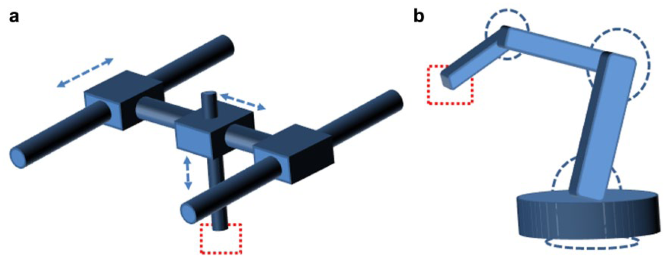
Schematic depiction of a (
In the biochemical laboratory, samples are almost always liquids. Microplates are the standard receptacles used to handle these samples due to their versatility.15,16 Efforts to create more cost-effective versions of microplates have been reported.17,18 In using robotic automated systems to handle microplates, the avoidance of liquid spillage19,20 during transport can often be more important than high-precision position and velocity control. Spillage can come about when the liquid receptacle is either subjected to inadvertent collision 21 or tilted excessively. The former is best detected using inertial sensors, one of the most common being the accelerometer, which is now widely available to measure acceleration in one, two, or three orthogonal axes. Most accelerometers today are microelectromechanical sensors (MEMSs), and work on the principle of measuring the displacement of a small proof mass etched into the silicon surface of the integrated circuit and suspended by small beams. According to Newton’s second law of motion, any acceleration applied to the device will displace the proof mass, causing the support beams to act as a spring, and the fluid (usually air) trapped inside as a damper. Various means to sense the proof mass displacement have been developed; however, the use of capacitive sensing offers arguably high sensitivity at very low cost. In addition, they can be developed into integrated circuit (IC) packages. 22
There are a variety of ways to measure rotation, which then allows the amount of tilt to be determined.23-25 An inexpensive but effective approach to measure the relative rotation between two linkages is via the use of optical rotary encoders 26 or potentiometers. 27 However, since actuators are used to rotate the arms of a SCARA, it is generally difficult to locate these sensors there, as well as to determine the amount of tilt. Actuators such as servomotors have potentiometers built inside them to provide information on the extent of rotation based on a reference, unlike stepper motors. However, this can only be used to instruct the servomotor to rotate to a certain degree; it cannot provide information on the extent to which the linkage it drives has actually moved. In theory, it is also possible to use accelerometers to measure rotation by referencing the constant gravitational acceleration vector. However, this is not expected to produce accurate rotation measurements.
Multisensor data fusion is a concept that enables information from several sources to be combined. Data fusion systems are now widely used in various areas such as sensor networks, robotics, video and image processing, and intelligent system design. Used in this vein to determine motion information more comprehensively, there is now a proliferation of cost-effective inertial measurement units (IMUs) that have been made possible by advances in MEMS technology. These are electronic devices that provide information on velocity, orientation, and gravitational forces, using a combination of accelerometers, gyroscopes, and magnetometers. 28
In this work, an approach of incorporating low-cost IMUs to an equally low-cost SCARA to imbue it with the ability to sense collision and determine the amount of tilt is described. Based on this, the system will be programmed to have an ability to raise an alarm, abandon its current operation, and return to its original position when any collision or excessive tilting is detected. A method to predict the location of any obstacle that causes a collision, based on the trajectory of the robotic arm as well as the acceleration feeds in the IMU, is also demonstrated.
Methods
Robotic Arm
The SCARA used was the AL5D from Lynxmotion (Swanton, VT). Its construction comprises aluminum brackets, aluminum tubing and hubs, injection-molded components, and custom-cut Lexan components. The arm is driven by a series of servomotors (Hitec HS-485HB, HS-805BB, HS-755HB, HS-645MG, and HS-422) located at the base, shoulder, elbow, wrist, and gripper, respectively. In order to accommodate the ability to transport microplates, the gripper range was extended by incorporating adaptors.
Robotic Arm Kinematics
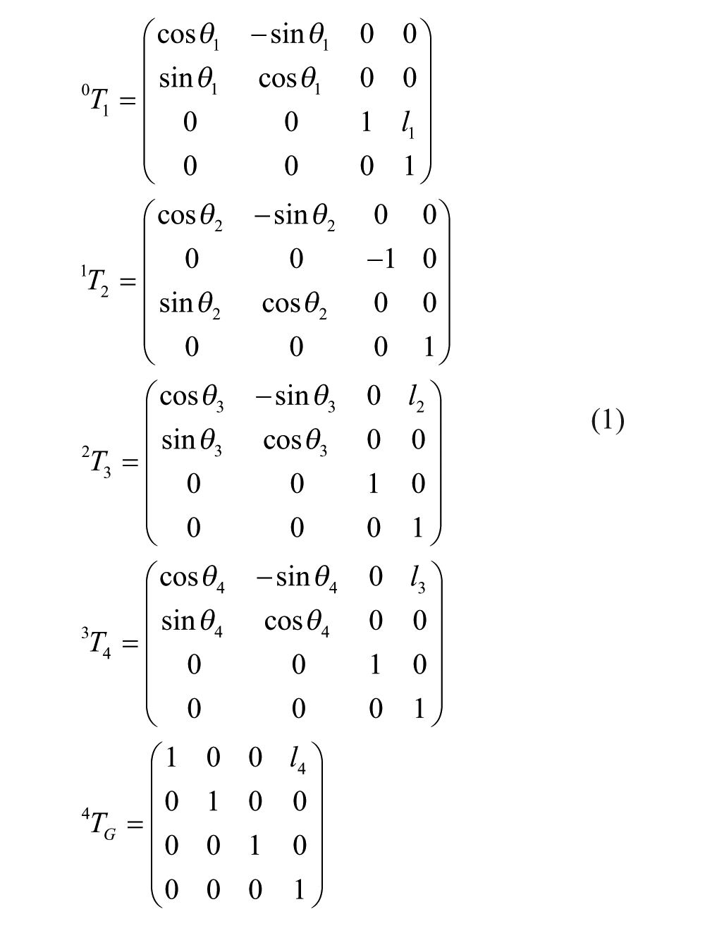
The Lynxmotion robotic arm was used under 4 degrees of freedom (see Fig. 2 ). To simplify understanding, the z axis is chosen to lie along the joint axis of each joint. The x axis is perpendicular to the z axis of any joint and the z axis of the next joint. The y axis is chosen to complete the right-hand coordinate frame for each joint. We used the standard Denavit–Hartenberg notation to depict the kinematics of the manipulator. 29 With this, the transformation matrices between the consecutive links are found to be
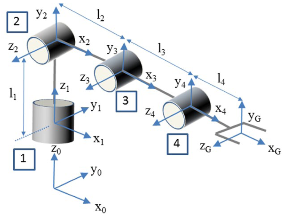
Axis structure of the Lynxmotion robotic arm used. The revolute joints are numbered for easy reference.
With these matrices, simple sequential multiplication will allow the base to be linked to the gripper using

Inertial Measurement Unit
The unit used (LSM9DS0, STMicroelectronics, Geneva, Switzerland) is a system-in-package featuring a three-dimensional (3D) digital linear acceleration sensor, a 3D digital angular rate sensor, and a 3D digital magnetic sensor. It has a linear acceleration full scale of ±2g/±4g/±6g/±8g/±16g, a magnetic field full scale of ±2/±4/±8/±12 G, and an angular rate of ±245/±500/±2000 dps. The LSM9DS0 has an I2C serial bus interface that supports standard and fast-mode data transmission (100 and 400 kHz) and a serial peripheral interface (SPI). It can be configured to generate interrupt signals on dedicated pins, and the thresholds and timing of interrupt generators are programmable.
Interfacing
The operations of the SCARA and IMU are coordinated through an ATmega328P single-board microcontroller (Arduino Uno). It has 14 digital input/output pins (of which 6 can be used as pulse width modulation [PWM] outputs), 6 analog inputs, a 16 MHz quartz crystal, a USB connection, a power jack, an in-circuit serial programming (ICSP)header, and a reset button. It operates under a voltage of 5 V and has a clock speed of 16 MHz. The device is highly compact with dimensions of 68.6 mm (length) by 53.4 mm (width), and weighing 25 g.
Collision Location Scheme
The collision location scheme is based on determining the angles (θ1, θ2, θ3, θ4, θG) as well as the coordinates of the gripper (xG, yG, zG) (see Fig. 3 ). Since the liquid sample has to be held without spillage, the gripper angle (θG) has to be constrained to remain constantly perpendicular to the global x-y plane. Performing an inverse kinematics procedure will yield the required parameters using the following set of equations:
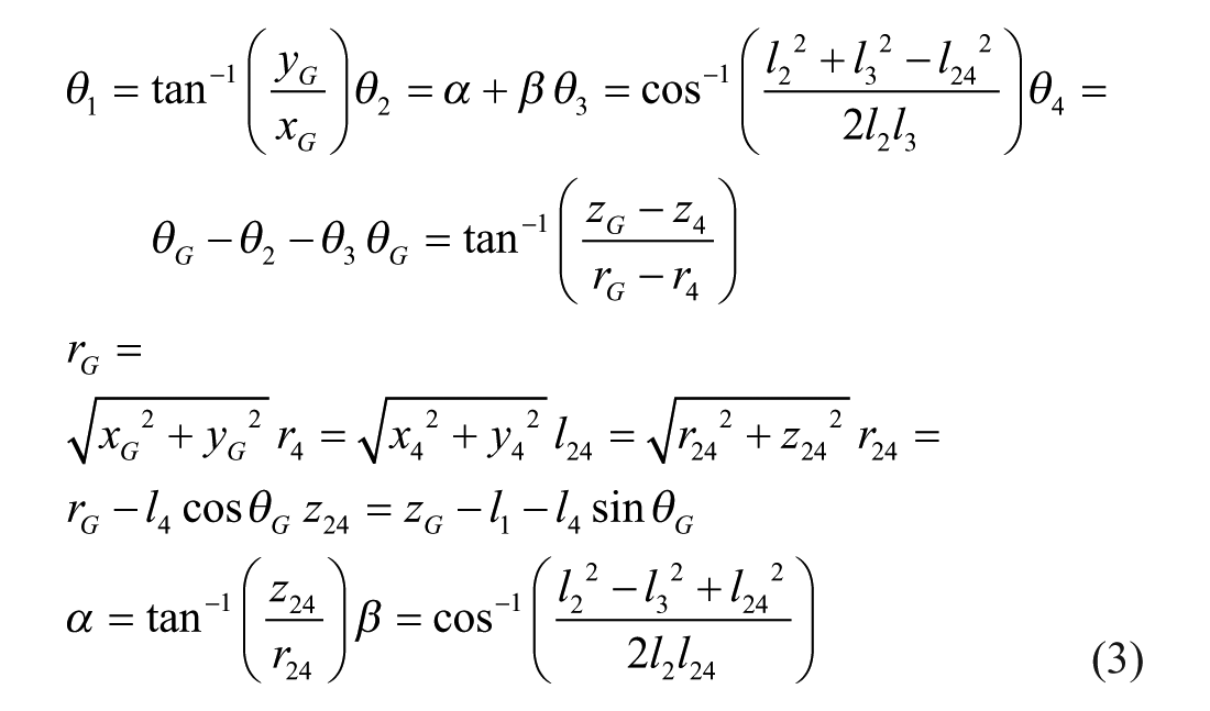
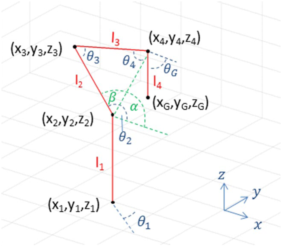
Coordinate system used to establish collision location.
The “anticipated position” of the arm refers to the position that the system sets the robotic arm to. However, collisions will result in a mismatch between this position and the actual position of the arm. Since the IMU is attached to the humerus (l2) segment of the robotic arm, it is used to calculate angles θ1 and θ2 . The accuracy of the fusion algorithm is dependent on the sensor sensitivity and the filter introduced. A convenient means is to model the variation in
The angle used to detect collisions is the angle between the anticipated linkage position and the calculated linkage position, and it can be denoted as δ. If
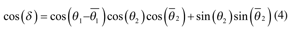
Such an analysis assumes that the robot arm only travels along a specific path, and that the robot arm remains stationary after any collision. Essentially, the position of the robotic arm can then be determined by retracing the travel path to locate the point where δ has reached its threshold setting. In the simulations, a threshold of δth = 2.5σ (σ1 = σ1 = σ2) is applied. It is important to note that knowledge of the direction in which that the arm was traveling prior to the collision is needed. If the arm is limited to move from one point to another in a linear fashion, the path of motion can be calculated from any start and end point of travel.
Microplate Positioner
Standard 96-well microplates (OptiPlate, PerkinElmer, Waltham, MA) were used in the experiments conducted. In order to locate the microplate for the robotic arm to collect from, a customized microplate positioner ( Fig. 4 ) for placement on an optical table was drafted using a computer-aided design software (Solidworks, Dassault Systems, Waltham, MA). Salient features incorporated into the microplate positioner include a low-profile region to facilitate easy microplate pickup, mounting holes to allow firm attachment to the optical table, and the use of tapers to guide any slight misplacement of the microplate to the optimal position. The design was sent to a 3D printer (UPrint SE Plus, Stratsys, Eden Prairie, MN), where the model was created using production-grade thermoplastic (ABS-P430, Stratsys) with soluble support material (SR-30, Stratsys).
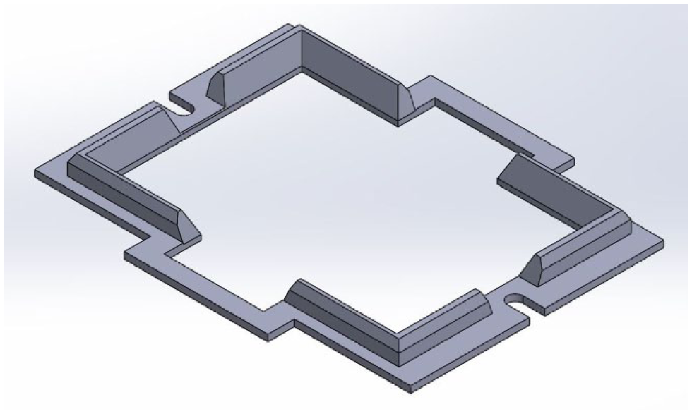
Computer-aided design of microplate positioner with features that include (
Results and Discussion
The robotic arm system used to transport microplates from a microplate positioner is shown in Figure 5 . Using the inertial measurement unit incorporated, efficient transport of microplates with liquid samples could be achieved. To ensure that spillage does not occur, the system needs to be able to detect a collision as soon as an obstacle is encountered. To test this, we instructed the robotic arm to swing in a planar fashion about the vertical as well as the horizontal. The outputs from the IMU were then used to compute θ2 in the former and θ1 in the latter.
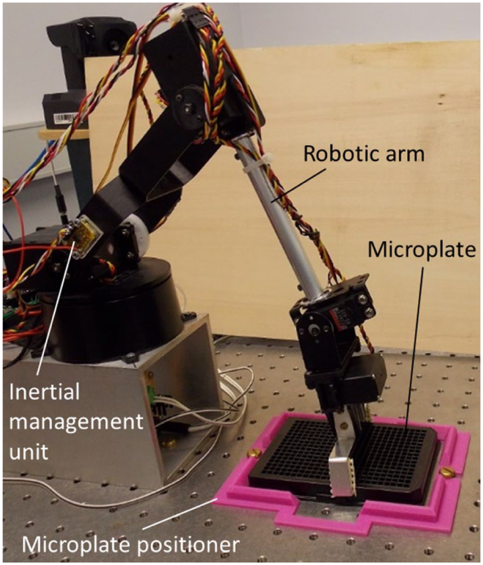
Robotic arm system developed with inertial measurement unit incorporated that is used to pick up microplates from a microplate positioner.
At this juncture, we make mention that we have applied a kinematic rather than dynamic modeling approach. With the latter, it will be necessary to previously determine the mass and mass moments of inertia data of the system in use. In addition, the calculations to be conducted will likely to be more involved, although more information in terms of forces and torques may be derived. In view of the objectives of this work, it was decided that a kinematic approach, used in conjunction with the signals of the IMU, would suffice.
In the vertical-plane robotic arm movement test, joint 2 (see Fig. 2 ) was programmed to rotate to provide the trace of θ2 as shown in Figure 6 . At around 24 s from the start, the arm was obstructed. Without any feedback, it will attempt to complete the programmed path, resulting in spillage of liquid. Using the signals from the IMU, it was possible to sense the presence of the obstacle, thus allowing the robotic arm to maintain a constant angle of θ2 (from 24 s onward), notwithstanding its original programmed trajectory (see Fig. 6 ). It was also possible to use only the three accelerometer signals from the IMU to arrive at the same outcome. This seemingly implies that the three-axis accelerometer can perform just as well as the IMU in tilt prevention.
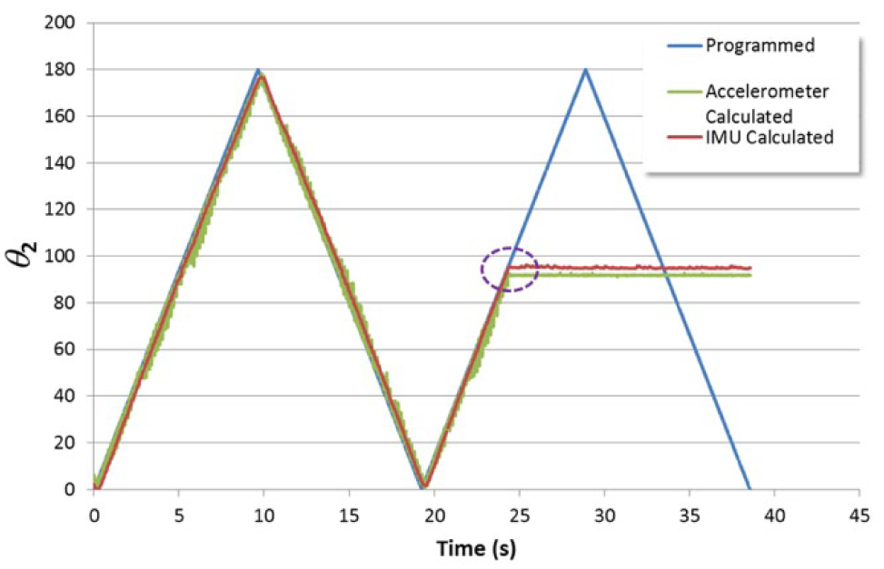
Plot of the angle θ2 as the robotic arm was programmed to swing in the vertical plane. At the point where an obstacle was encountered (purple dashed circle), both the accelerometer and IMU were able to detect the collision and keep the angle constant.
The difference in performance between the IMU and accelerator was observed in the trace of θ1 when the robotic arm was programmed to undergo the horizontal movement test, as shown in Figure 7. As in the case of the vertical movement test, the signals from the IMU enabled the obstacle to be sensed, thereby allowing the robotic arm to maintain a constant angle of θ1 (from 24 s onward). The use of the accelerometer signals alone, however, could not provide detection of any changes in θ1. Since it is not feasible to prevent horizontal movements of the arm, the use of the IMU is necessary to avoid spillage. The trade-off in terms of cost is marginal, with the IMU and accelerometer breakout boards costing about US$40 and US$20, respectively. The IMU, however, imposes the need to process more data channels. One strategy to reduce this load may be to poll the accelerometer inputs alone when vertical movement instructions to the robotic arm are made, while the other inputs (magnetometer and gyroscope) are used exclusively for horizontal movements.
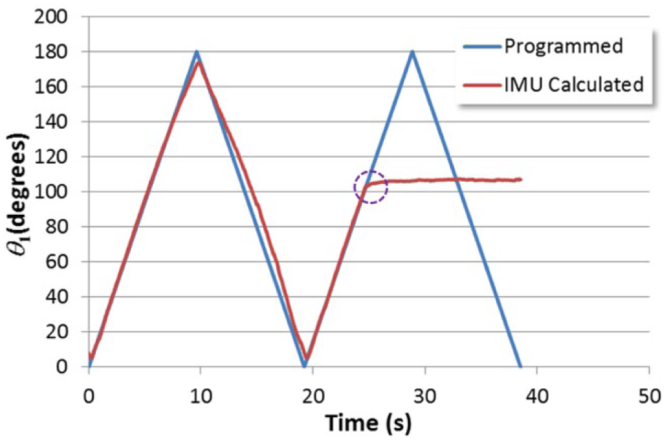
Plot of the angle θ1 as the robotic arm was programmed to swing in the horizontal plane. At the point where an obstacle was encountered (purple dashed circle), only IMU was able to detect the collision and keep the angle constant. The accelerator could not provide any data to determine θ1.
Once a collision is detected, it will be instructive to approximate where the obstacle may be. From there, two remedies are possible. The first will be to issue an instruction to a nearby operator to remove the obstacle, while the second is to chart another path that will avoid it altogether. Figure 8 presents a snapshot of the robotic arm that is programmed to travel along a specific path. If a collision were to be sensed at the moment where the programmed positions of the robot arm components are as indicated in green, then the possible locations of the obstacle can be predicted as shaded in red. An animated version of this for the full extent of arm movement through the travel path is given as supplementary material. Admittedly, the method here lacks fidelity compared to other reported approaches to estimate obstacle location. 30 However, our system does not require the use of costly torque sensors located at all the articulating joints. It should be noted that algorithms,31,32 some of them with high degrees of complexity, have been developed to detect collisions based on various sensing inputs. The implementation of such schemes will likely incur high computational overheads. Considering that the goal here is to prevent spillage of the microplates in a simple manner, it appears that alerting a nearby operator to remove the obstacle will likely be the most viable remedy when a collision is detected.
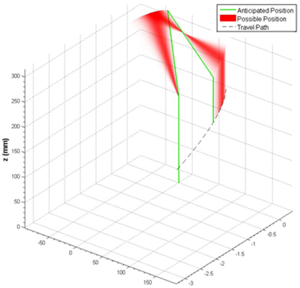
Snapshot of the robotic arm components (green) at the moment of collision as it undergoes movement through a path indicated by the grey dash line. The likely locations of the obstacle are highlighted in regions shaded in red.
In the event of spillage occurring due to an inadvertent collision, it will be necessary to implement measures of cleanup before the automated system can be made to refunction. Robotic cleanup of spills has been considered for the general environment, 33 but not in the context of the laboratory to the best of our knowledge. Since the position of collision can be determined, it will provide some basis for the location of any spill to be estimated. This will then permit the same SCARA manipulator to put away the microplate and pick up a cleaning implement (i.e., sponge) to collect the spillage.
Conclusion
A low-cost selective compliant articulated robotic arm for liquid spillage avoidance was developed. It was based on polling the outputs from an IMU as the robotic arm was used to transport microplates with liquid samples. In the vertical-plane robotic arm movement test, the signals from the IMU and accelerometer were able to sense the occurrence of robotic arm obstruction. In the horizontal movement test, the signals from the IMU enabled the obstacle to be sensed, but this was not possible using the accelerometer outputs alone. Since it is not feasible to prevent horizontal movements of the arm, the use of the IMU is necessary to avoid spillage. Using a calculation method developed, it was possible to chart the regions where the obstacle was likely to be located when a collision occurred. While it lacks fidelity compared to other reported approaches to estimate obstacle location, it does not require expensive torque sensors to be installed at all the articulating joints.
Footnotes
Acknowledgements
Early contributions by Ian Gralinski (now with Invetech Australia) and Matthew Hendry are appreciated.
Declaration of Conflicting Interests
The authors declared no potential conflicts of interest with respect to the research, authorship, and/or publication of this article.
Funding
The authors received no financial support for the research, authorship, and/or publication of this article.