
Abstract
Matrix-assisted laser desorption/ionization (MALDI) imaging mass spectrometry (IMS) is a powerful tool for investigating the distribution of proteins and other molecules within biological systems through the in situ analysis of tissue sections, enabling molecular histology. MALDI IMS can determine the distribution of hundreds of unknown compounds in a single measurement while maintaining spatial and molecular integrity. The matrix spraying stage is a key factor in making this technique more sensitive and robust. In this article, we describe a custom-made matrix sprayer (Langartech), which is both inexpensive (estimated cost of about €3000, or $3500) and reliable compared with the alternatives present in the market today, with prices greater than €20,000 ($25,000). Several comparisons were made between our Langartech sprayer and one of the high-end matrix sprayers commercially available: ImagePrep (Bruker Daltonics). Focusing on lateral resolution and observed peak intensities, overall results show that our sprayer behaves in a very competitive fashion, especially when taking into account the huge difference in sophistication level and price.
Introduction
Matrix-assisted laser desorption/ionization (MALDI) imaging mass spectrometry (IMS) is an innovative technique that links the universal detection capability of mass spectrometry with molecular histology positional information, generating mass spectra correlated to known locations within the tissue, thus enabling molecular histology.1,2 This technique has enormous applications in clinical medicine. For example, pathologists are able to correlate the distribution of specific compounds with pathologically interesting features.3–5 Recent work has also demonstrated the capacity to create three-dimensional molecular images using the MALDI imaging technology and co-registration of these image volumes to other imaging modalities such as magnetic resonance imaging.6,7
MALDI IMS can reveal the distribution of hundreds of ion signals ranging in size up to 20,000 Da. This information can be used to determine tumor margins, drug distribution throughout a tissue or organism, and proteomic profiles under different experimental or therapeutic conditions. To date, MALDI IMS has already been applied to map several classes of biomolecules including proteins,8,9 peptides,10,11 metabolites,12,13 and lipids14,15 in biological tissues.
The primary downside of the MALDI IMS protocol is the matrix application stage, which determines the sensitivity, spatial resolution, and overall quality of the obtained image. The matrix drop must be maintained as small as possible to increase spatial resolution. This is particularly critical in protein or peptide analyses because the matrix dilution is responsible not only for ionization but also for analyte extraction. There is a critical balance between the time the sample is wet and when it is dry: a higher wetting time increases extraction, providing greater sensitivity, but also increases diffusion, resulting in lower lateral resolution. Thus, if too much solvent is applied to the sample, then the analytes delocalize on the tissue and much of the spatial information is lost. On the other hand, if the sample is too dry, poor extraction will be achieved, and spectra quality will be affected. 16
Because of this critical scenario, several automated matrix sprayers have been marketed, using different procedures to address the aforementioned challenge, solubilization versus delocalization, ensuring optimal conditions for increasing both sensitivity and spatial resolution.17,18
The drawback of this equipment is mainly economical: its cost ranges from approximately €20,000 to more than €40,000 ($25,000–$40,000). Thus, we have created a customized matrix sprayer with a cost-sensitive goal in mind that does not compromise overall performance. The initial requirements for this equipment were to keep it simple but reliable, using mass production with easy-to-find components, ensuring ease of maintenance and low overall cost. This sprayer has been called Langartech 1.0 from the Basque name for fine rain or drizzle, “Langar,” and the added well-known suffix “Tech.” It consists in a commercially available pneumatic sprayer on top of a pneumatically movable base containing the platform on which the sample slide is placed. The system has several degrees of freedom to optimize the spray and it is mounted in a closed chamber. To operate and automatize the process, the system is equipped with a conventional, programmable logic controller programmed with a basic operational program.
Experimental
Langartech Sprayer
The Langartech 1.0 sprayer consists of a pneumatically movable base, called a table, with a detachable stainless steel platform on which the microscope slide (with the sample) is placed. A commercially available pneumatic sprayer head that uses the Bernoulli principle to nebulize the matrix solution is mounted above the platform. This sprayer head does not move, but it has X-Y-Z degrees of freedom to optimize the spray. All of these components are mounted in a closed chamber with two air extraction fans to enhance the drying stage. Finally, the sprayer has a conventional PLC to allow implementation of a basic program to operate the wet/dry cycles.
Pneumatic Diagram
To design and develop a low-cost industrial mechanism, two main options were analyzed at the beginning of the project: electric drives (whose costs have dramatically decreased recently) and pneumatic actuators, which provide a well-established solution for simple movement devices. Because of the sprayer system requirements and the need to use pressurized air, pneumatic systems were used for all actuators.
The table, on which the sample to be prepared is located, is controlled by twin double effect actuators to balance inertial forces and achieve a smooth and reliable swaying motion ( Fig. 1A, B ). These two actuators are controlled by the same spool valve and with one flow restrictor per cylinder; it is possible to achieve fine control of platform’s feed rate.
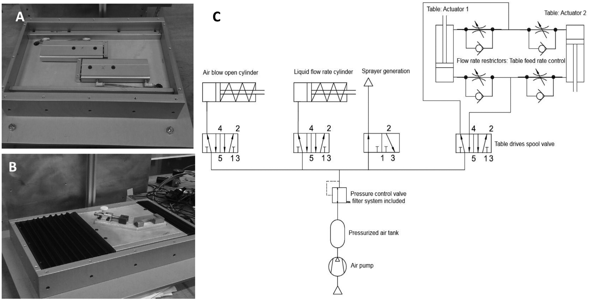
The nozzle works with two internal actuators for controlling air and liquid flow rates. A pressurized air inlet valve in the nozzle is used to generate the spray. Thus, the pneumatic system is composed of four main arms (with one spool valve for each arm), four flow rate restrictors to properly control the table’s swaying movement, an overall circuit air pressure control valve (including air filtering), and a reservoir tank to moisten the air flow rate fluctuation and to reduce the pressure drop when maximum air flow rate is necessary. All of these devices are illustrated in the schematic diagram in Figure 1C .
Electrical and Logical Diagram
The pneumatic actuators are electrically regulated by a SIEMENS Simatic S7-1200PLC (Siemens AG, Munich, DE). This type of controller is based on simple architectural hardware (an old-fashioned CPU), but despite its specs in clock-time and big data management, the PLC systems are well established in devices in which maximum reliability is demanded and not very complex computations are required, as in the present case. Dedicated software was developed to program the working cycles in which different variables such as curing cycles and time, drying time, air blowing cycle, and overall repetitions are defined by the user. All other inputs are fixed in the program, but it is quite easy to change the PLC software programming if needed. The software developed for the device has “Next” input screens, all as per the scheme shown in Figure 2 . This program allows several variables to be changed: spraying cycle (number of passes), waiting time (between spraying cycle and wetting cycle), drying cycle (number of passes), and complete cycles (number of spraying and wetting cycles).
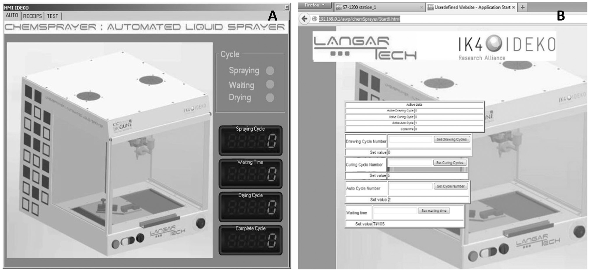
Two main configuration software screens: (
The spraying software implementation is simple and allows for quick changes to both painting/wetting cycles and the number of layers that will be placed over the tissue samples ( Fig. 3 ).
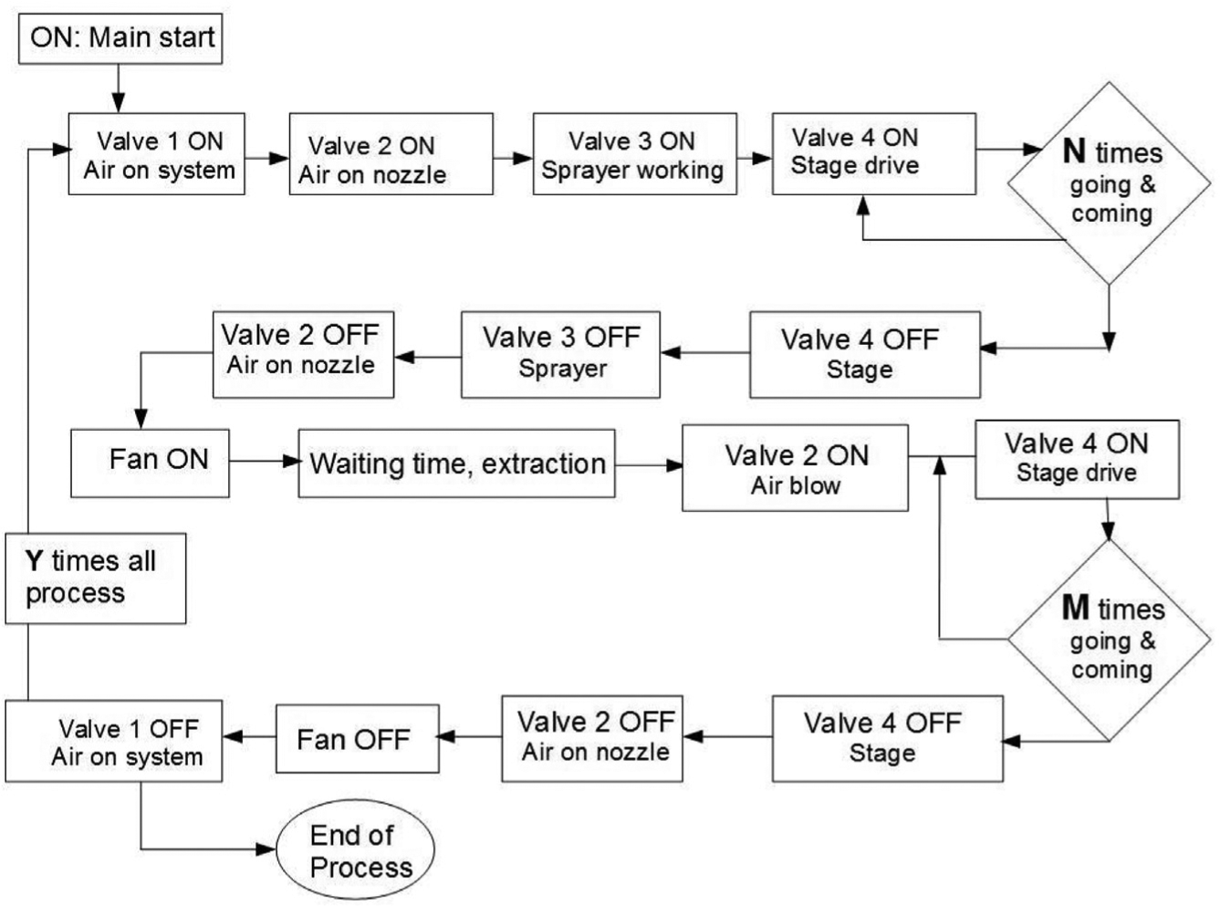
Block diagram of implemented logic to programmable logic controller system.
Sprayer and Nebulization Chamber
The sprayer head consists of a commercially available pneumatic sprayer head Lumina ST-6 (Fuso Seiki Co., Tokyo, Japan) with two separate air hoses for piston operation and atomization and low-pressure operation, based on the Venturi effect, to nebulize the matrix solution. This sprayer has two regulator screws, one for air flow and the other for liquid flow rate.
The sprayer head does not move, but it has X-Y-Z degrees of freedom to optimize the spray. All of these components are mounted in a closed chamber with two air extraction fans to enhance the drying stage ( Fig. 4 ).
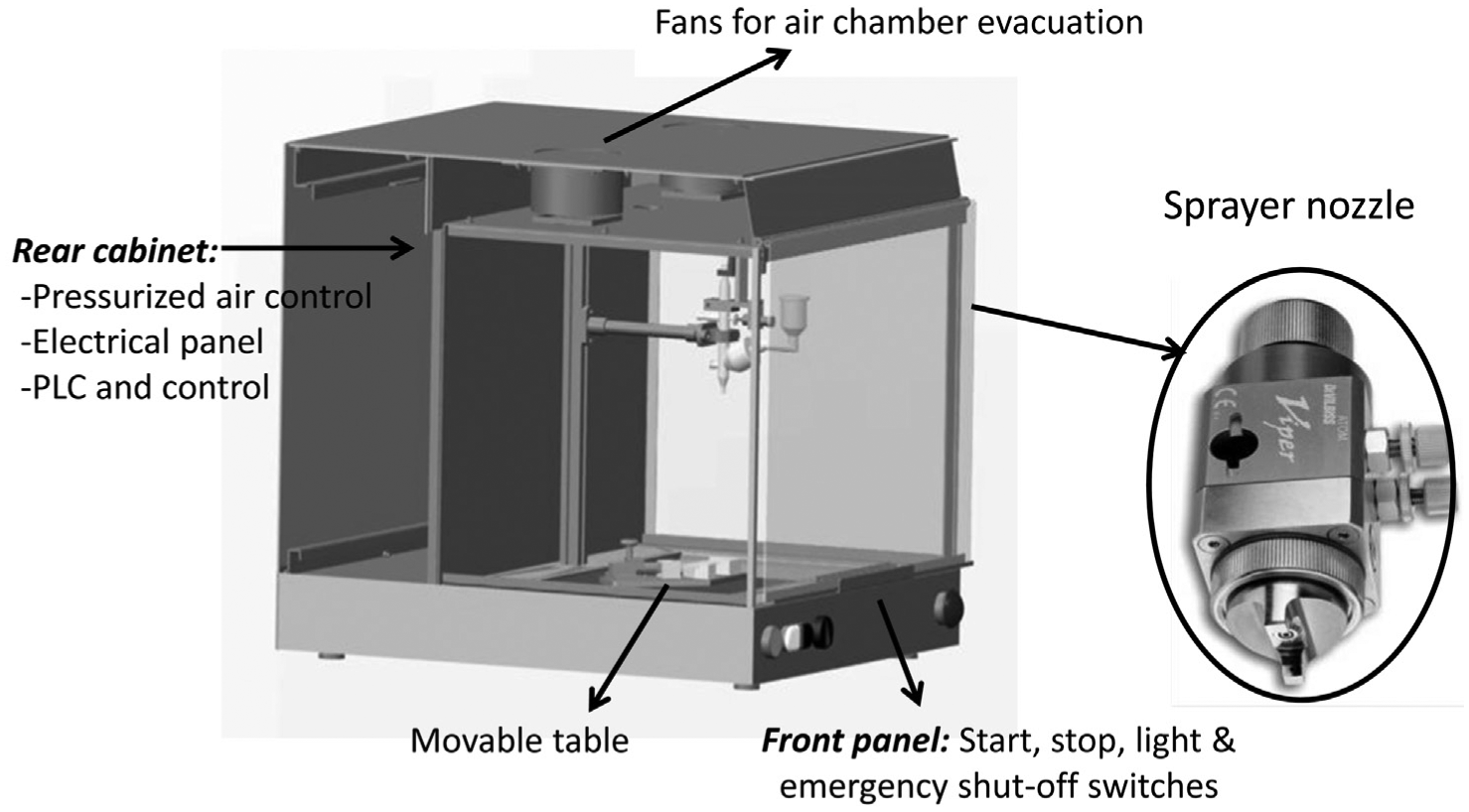
Nozzle configuration of the Langartech platform, main subsystems, and overall structural design.
Chemicals and Reagents
Sinapinic acid (3,5-dimethoxy-4-hydroxycinnamic acid, SA) matrix was purchased from Alfa-Aesar (Karlsruhe, DE). Trifluoroacetic acid (TFA) was purchased from Pierce (Thermo Scientific, Waltham, MA). Acetonitrile (ACN) was purchased from Labscan (Gliwice, Poland).
Tissue Sampling, Sectioning, and Storage
Mice (X days) were euthanized by CO2 asphyxiation. Harvested kidneys were flash frozen in liquid nitrogen to preserve the native tissue morphology and stored at −80 °C. All animal experimentation was conducted in accordance with the Spanish Guidelines for the Care and Use of Laboratory Animals, and protocols were approved by the CIC bioGUNE Ethical Review Committee that is accredited by the Association for Assessment and Accreditation of Laboratory Animal Care and the Office of Laboratory Animal Welfare. For IMS analysis, kidney tissues were sectioned into 12 µm thick slices at −25 °C using a Leica CM3050 cryostat (Leica Microsystems GmbH, Wetzlar, DE) and thaw mounted onto ITO-coated glass microscope slides (Bruker Daltonics, Bremen, DE) according to previously published protocols.19–21 Prior to sectioning, tissues were removed from storage at −80 °C, embedded in OCT (optimum cutting temperature compound [Sakura-Finetek, Tokio, JP]), and placed in the cryostat for 20 min at −20 °C. Immediately after mounting the sections, slides were desiccated for 30 min. Following desiccation, slides were delipidized using a standard Carnoy procedure (consecutive immersions in 70% ethanol [1 min], 100% ethanol [1 min], Carnoy reagent [3 min], 100% ethanol [1 min], 0.1% TFA [1 min], and 100% ethanol [1 min]). After delipidation, samples were desiccated again for 20 min. Figure 5 shows the main flowchart for MALDI-IMS sample preparation and acquisition.
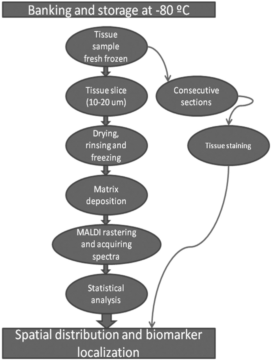
Typical flowchart of matrix-assisted laser desorption/ionization imaging mass spectrometry. The main bottleneck of the procedure is the fourth step: matrix deposition.
MALDI Matrix Deposition
For IMS measurements, the SA matrix (15 mg/mL in 70:30 ACN with 0.1% TFA) was sprayed onto the tissue sample using the Langartech (Ideko-IK4, Elgoibar, ES) custom-made sprayer. A standard in-house spraying protocol was used, with a three-pass spraying stage followed by a five-pass drying stage. Both stages were repeated 10 times to achieve optimal layer deposition.
For comparison, another commercial sprayer was used (Imageprep; Bruker Daltonics, Bremen, DE) with the same matrix using Bruker’s standard procedure for protein imaging.
MALDI Mass Spectrometry
IMS of tissue sections was performed using a Bruker Daltoniks Autoflex III Smartbeam MALDI-TOF/TOF mass spectrometer (Bruker Daltonics) equipped with SmartBeam Nd:YAG/355 nm laser operating at a repetition rate of 100 Hz. Imaging data acquisitions were performed in linear geometry under optimized delayed extraction conditions, in a mass range of 1000 to 20,000 Da in positive ionization mode. Instrumental parameters (delayed extraction parameters, laser fluence, detector gain) were set to obtain the best signal-to-noise ratio and remained constant throughout. For IMS data acquisitions, 500 shots were summed per array position with a spatial resolution of 100 µm. Software used for data acquisition was FlexControl 3.0 (Bruker Daltonics).
Data Analysis
Data analysis was performed with FlexImaging 3.0 (Bruker Daltonics). ClinProt Tools 2.2 (Bruker Daltonics) was used to obtain peaking and basic statistics. All data comparisons were performed equally, summarizing signals above a signal-to-noise ratio greater than 3.0. Routinely, all spectra are baseline corrected using a Top Hat algorithm with a 10.0% minimal baseline width and smoothed using a Savitzky-Golay algorithm with a 2.0 width (m/z) and five cycles. Data reduction of 10 was used to prevent running out of memory. All spectra were recalibrated using 1000 ppm of maximal peak shift and 30% match to calibrant peaks.
For display, imaging data were loaded using FlexImaging 3.0, and a list of masses corresponding to peaks was created.
Results and Discussion
The matrix coating on the tissue surface should be as uniform as possible. To maximize the spatial resolution of the image, the crystal size should be as small as possible. Using an automatic matrix sprayer provides homogeneity, reproducibility, and reduced spot size.
Several different wet/dry cycle protocols were evaluated. An optimal layer deposition was achieved with the following spraying protocol: a three-pass spraying stage followed by a five-pass drying stage. Both stages were repeated 10 times to achieve the final layer deposition shown in Figure 6 . This deposition showed droplet diameters <200 µm and an average droplet size of ~40 µm ( Fig. 6A, B ). Unfortunately, some randomly dispersed spots of ~60 µm appeared. Increasing the number of spraying layers did not significantly reduce the number of spots. Matrix deposition with Bruker’s ImagePrep shows a similar macroscopic pattern, also very uniform ( Fig. 6C ) and also with droplet diameters <200 µm, slightly smaller than using Langartech ( Fig. 6D ). The spots observed with the Langartech procedure are not present. Overall, the matrix deposition with ImagePrep seems to be slightly more homogeneous, but not significantly so.
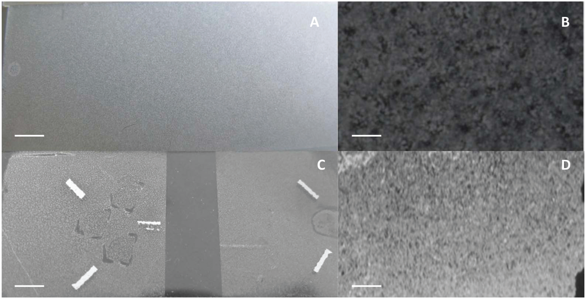
These results demonstrate that although there are several differences between the two matrix deposition methods, the differences are slight, and the systems are comparable, with more similarities than differences. Spots in the Langartech matrix deposition could be due to differences in the drying procedure. The ImagePrep drying procedure consists of filling the sample chamber with N2, whereas the Langartech process consists of dry air emissions from the nozzle. This latter procedure could favor the mixing of droplets, thus creating the spots. In any case, the size of the spots and their number do not seem to be problematic, although a slight decrease in the achieved lateral resolution could be possible. To summarize, the delivery of a homogeneous matrix layer is very reproducible in both systems, and this allows for consistent matrix thickness.
Comparison of Mouse Kidney MALDI IMS Images Obtained after Image Prep Matrix Spray and Langartech Spray
Slices 10 to 15 µm in thickness are normally recommended for MALDI IMS analyses. In this experiment, two 10 µm slices of mouse kidney were cut equatorially using the previously described procedure. It should also be noted that for protein and peptide imaging, the samples were washed with an organic solvent to remove small molecules including lipids and OCT used for mounting; however, a washing step should be performed only with solvents that do not dissolve the analytes of interest and should be avoided for small-molecule analysis. As mentioned in the Materials and Methods section, we chose the Carnoy procedure because of the good results obtained in previous experiments.
For a practical experiment, a tradesoff must be made between reasonable data acquisition size, spatial resolution, and the time spent on acquiring MS imaging data. Usually, 100 µm is a good compromise, so we chose this resolution for comparison.
The results obtained demonstrate that although there are some differences between Langartech and ImagePrep spraying methods, these are minimal, with similar intensities (from 10 to 20 counts) and peak counts (225 peaks Langartech v. 201 peaks ImagePrep [S/N >5]; Fig. 7A, B ).
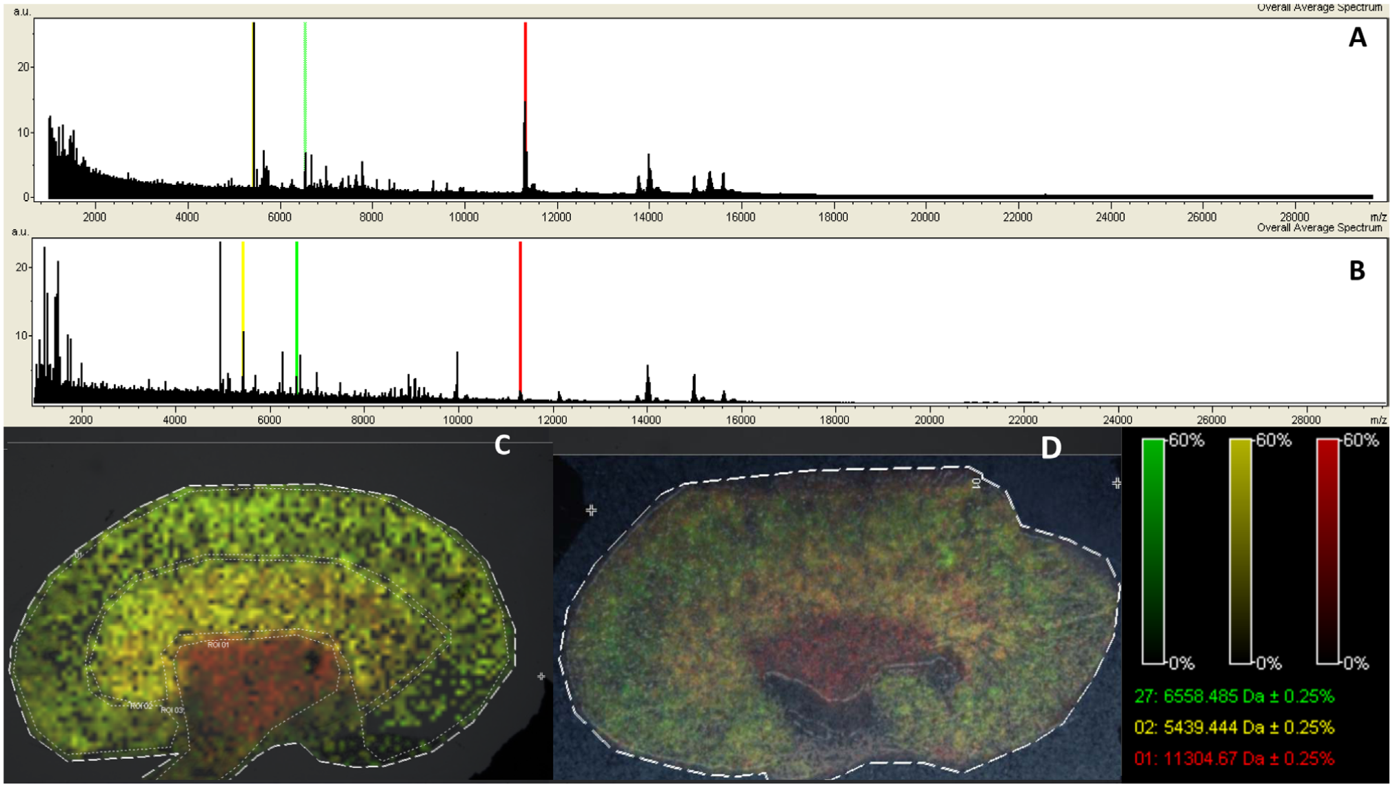
Once the set of mass spectra from a MALDI IMS experiment has been acquired, the image for each of the detected ions is generated, with each pixel representing a laser irradiation spot from the surface of a tissue section. Combining all of the individual pixels with different ion intensities across the tissue section from a MALDI IMS experiment reflects the ionization of target analytes within the tissue.
The obtained MALDI IMS images are composed of the spatial distribution of the three most intense peaks that are spatially characteristic of the three main kidney regions (cortex, medullae, and pelvis): 11,305 Da (red, distributed mainly in pelvis, 5439 Da; yellow, distributed mainly in medullae, and 6558 Da; green, distributed mainly in cortex). From a methodological point of view, the lateral resolution achieved seems adequate at 100 µm. Also, there is no evidence of an excess of diffusion with either system. The composition shows all three different structures: cortex, medullae, and pelvis ( Fig. 7C, D ).
We achieved lateral resolutions of up to 100 µm using our Langartech matrix sprayer. However, ImagePrep shows a slightly better longitudinal resolution. The resolution with Langartech is partly limited by the presence of spots in the matrix surface. Further optimization could be attained in sample preparation by trying to minimize the lack of deposition that is causing the holes.
Conclusion
The MALDI imaging mass spectrometry is a proven analytical platform for proteomics discovery that offers excellent sensitivity and rapid analysis time. In one single experiment, scientists are able to obtain information on a wide range of compounds, known and unknown, without the need for prior labeling. The critical drawback of this technique is that most matrix deposition systems face a difficult challenge: absorption versus delocalization. This shortcoming can be greatly avoided with the use of an automatic sprayer system. Currently the cost of these systems is relatively high. The Langartech MALDI sprayer uses commercially available and cost-effective parts to create a system that can compete with the much more expensive systems. The Langartech system provides good MALDI IMS images at the target resolution of at least 100 µm.
Footnotes
Acknowledgements
We thank Dr. Juan Anguita for technical assistance in obtaining the mouse kidneys. In addition, Proteomics Platform at CIC bioGUNE thanks ProteoRed-ISCIII, Basque Government ETORTEK program, and Bizkaia County for their financial support.
Declaration of Conflicting Interests
The authors declared no potential conflicts of interest with respect to the research, authorship, and/or publication of this article.
Funding
The authors received no financial support for the research, authorship, and/or publication of this article.