
Abstract
Diagnostics, drug delivery, and other biomedical industries rely on cross-linking ligands to microbead surfaces. Microbead functionalization requires multiple steps of liquid exchange, incubation, and mixing, which are laborious and time intensive. Although automated systems exist, they are expensive and cumbersome, limiting their routine use in biomedical laboratories. We present a small, bench-top robotic system that automates microparticle functionalization and streamlines sample preparation. The robot uses a programmable microcontroller to regulate liquid exchange, incubation, and mixing functions. Filters with a pore diameter smaller than the minimum bead diameter are used to prevent bead loss during liquid exchange. The robot uses three liquid reagents and processes up to 107 microbeads per batch. The effectiveness of microbead functionalization was compared with a manual covalent coupling process and evaluated via flow cytometry and fluorescent imaging. The mean percentages of successfully functionalized beads were 91% and 92% for the robot and manual methods, respectively, with less than 5% bead loss. Although the two methods share similar qualities, the automated approach required approximately 10 min of active labor, compared with 3 h for the manual approach. These results suggest that a low-cost, automated microbead functionalization system can streamline sample preparation with minimal operator intervention.
Keywords
Introduction
Microbeads functionalized with biomolecules are used in a variety of biological assays, including bioseparations,1,2 targeted imaging and contrast agents,3,4 flow cytometry diagnostic reagents,5,6 and smart drug delivery.7–9 Microbeads are advantageous as a bioassay platform because a high density of biomolecules can be attached to a comparatively large surface area using a nominal quantity of expensive biomolecules. Microbeads are also a convenient platform to discover the presence of ligands and antigens on the surface of cells, as described by the identification of antigens on cells using the Luminex system.10–13 Microbeads are also frequently employed to understand cell response to biological stimuli14,15 or to enhance the contrast of imaging techniques.16,17
However, the preparation of functionalized microbeads is time and labor intensive, causing frequent bottlenecks in laboratory experimentation. Manual processing of microbeads requires trained personnel to perform more than 25 individual processing steps, including repeated pipetting, washing, liquid exchange, centrifugation, and mixing. The process is laborious and requires up to 3 h of constant processing and attention, with a large portion of the time spent waiting for various step completion. Because of the large quantity of concentrated effort and time required, human error compounds and contributes to inadequate preparation. 18
The repetitive nature of the functionalization process is well suited for automation. A variety of high-throughput liquid-handling systems have been developed to functionalize microbeads. The JANUS Automated Workstation (Perkin Elmer), Freedom EVO (TECAN), and AMBR (Srtorius Stedim Biotech) are adaptable robotic systems for handling microbeads and microplates that feature a single- or dual-arm platform with multiple pipette tips and gripper arms to directly manipulate liquid reagents and standard containers. Another liquid-handling robot technology is the KingFisher (Thermo Electron), which uses magnetics combined with dispensable plastic tips to rapidly move liquid-containing magnetic beads from one vessel to the next. Although these systems are adaptable to many applications, the cost and physical footprint prohibit numerous biomedical applications in which bead functionalization is needed on a smaller scale, particularly in academic laboratories.19–21 To address this issue, a new, low-cost liquid-handling robot was constructed to automate the attachment of biomolecules to microbeads for a variety of biotechnological applications.
The robot controls the transfer and mixing of several liquid reagents, including the biomolecule solution, coupling buffer, and washing solution ( Fig. 1 ). Three micropumps independently transfer the liquid reagents from the loading ports through tubing to the functionalization chamber containing the microbeads. The microbeads are retained in the chamber through the use of a submicron pore filter, with maximum pore diameter less than the minimum bead diameter. Discarded liquid reagents and liquid waste materials are removed from the chamber via vacuum pump. An integrated magnetic stir rod, driven by a 12V DC motor at 200 Hz, mixes the reagents. Finally, a programmable ATmega 328P-PU microcontroller allows the user to define the functionalization steps, including reagent pumping, mixing, incubation, and liquid removal. The compact device, in its entirety, occupies a small footprint of 16.9 cm2 and a total volume of 2500 cm3.
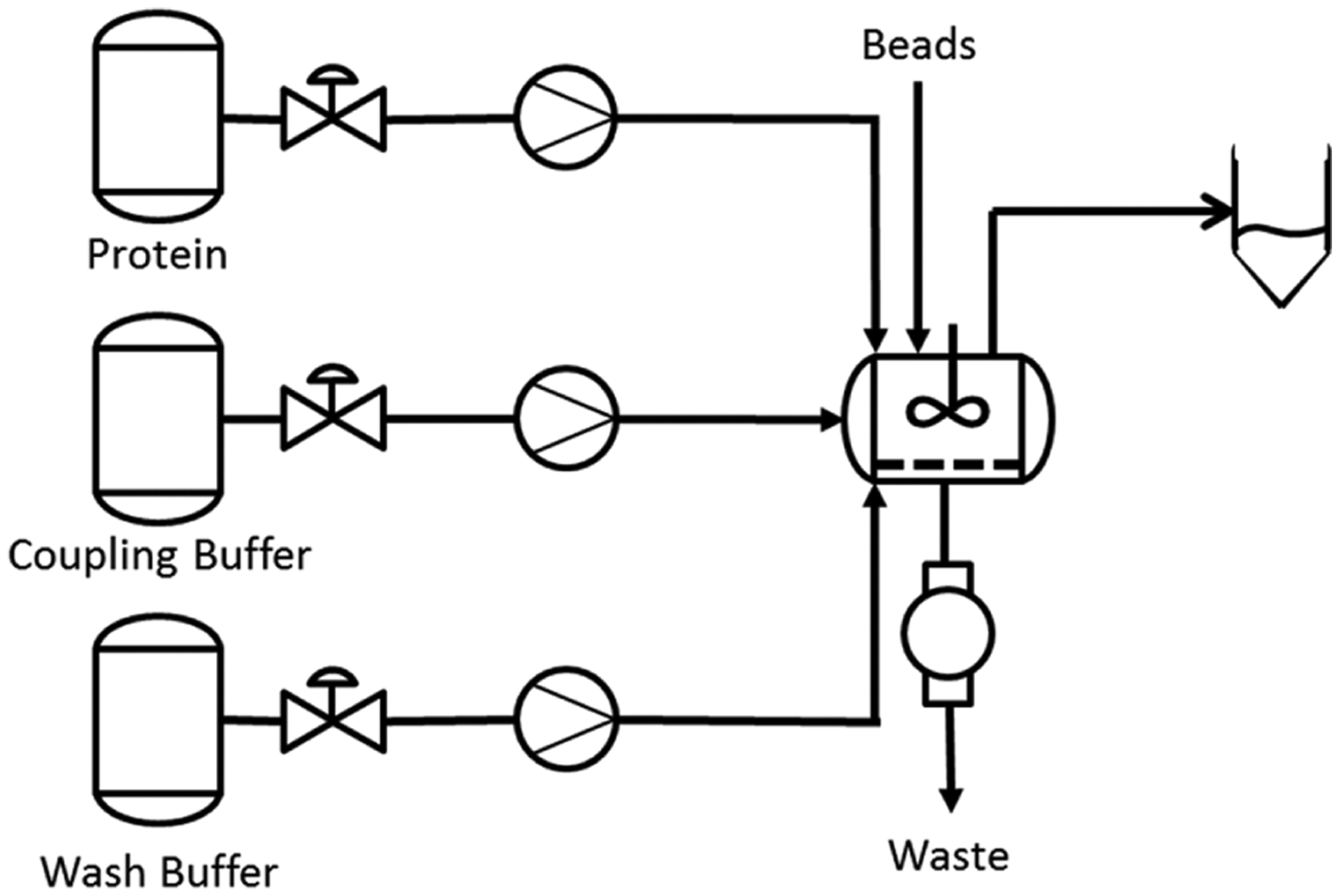
Bead functionalization process schematic that is implemented by the robot liquid-handling system. The timing of the valves, pumps, and mixing chamber is set by the user through microcontroller programming.
The biomolecules attached to the microbeads can include proteins and nucleic acids. In the initial proof of concept, proteins were attached to polystyrene microbeads, because proteins are generally more difficult to functionalize because of the need for a highly controlled liquid environment with proper chemical composition, pH, temperature, mixing speed, and vorticity in the solution. The covalent cross-linking of protein amine groups to carboxylated polystyrene microbeads was activated chemically through the 1-ethyl-3-(3-dimethylaminopropyl)-carbodiimide (EDAC) reaction.
Implementation of Liquid-Handling Automation
Functionalization Process
The robot was constructed to automate the manual process implemented by laboratory technicians. First, stock bead solution is added to the functionalization chamber and three liquid reagents, phosphate-buffered saline (PBS), coupling buffer (purchased from Thermo Scientific), and bovine serum albumin (BSA) protein that was previously labeled to a fluorescein isothiocyanate (FITC) dye (purchased from Sigma-Aldrich), are prepared and loaded into designated reservoirs. The microcontroller in the robot simulates the manual process by washing the beads in PBS, followed by coupling buffer, and concluding with the fluorescently labeled protein, FITC-conjugated BSA (FITC-BSA) solution. After incubating the microbeads at room temperature with the reagents, the beads are thrice washed and suspended in PBS for testing. Figure 2 provides an overview of the manual bead functionalization process flow implemented by a given user. This process flow provides the foundation for the standard protocol implemented by the automated system.
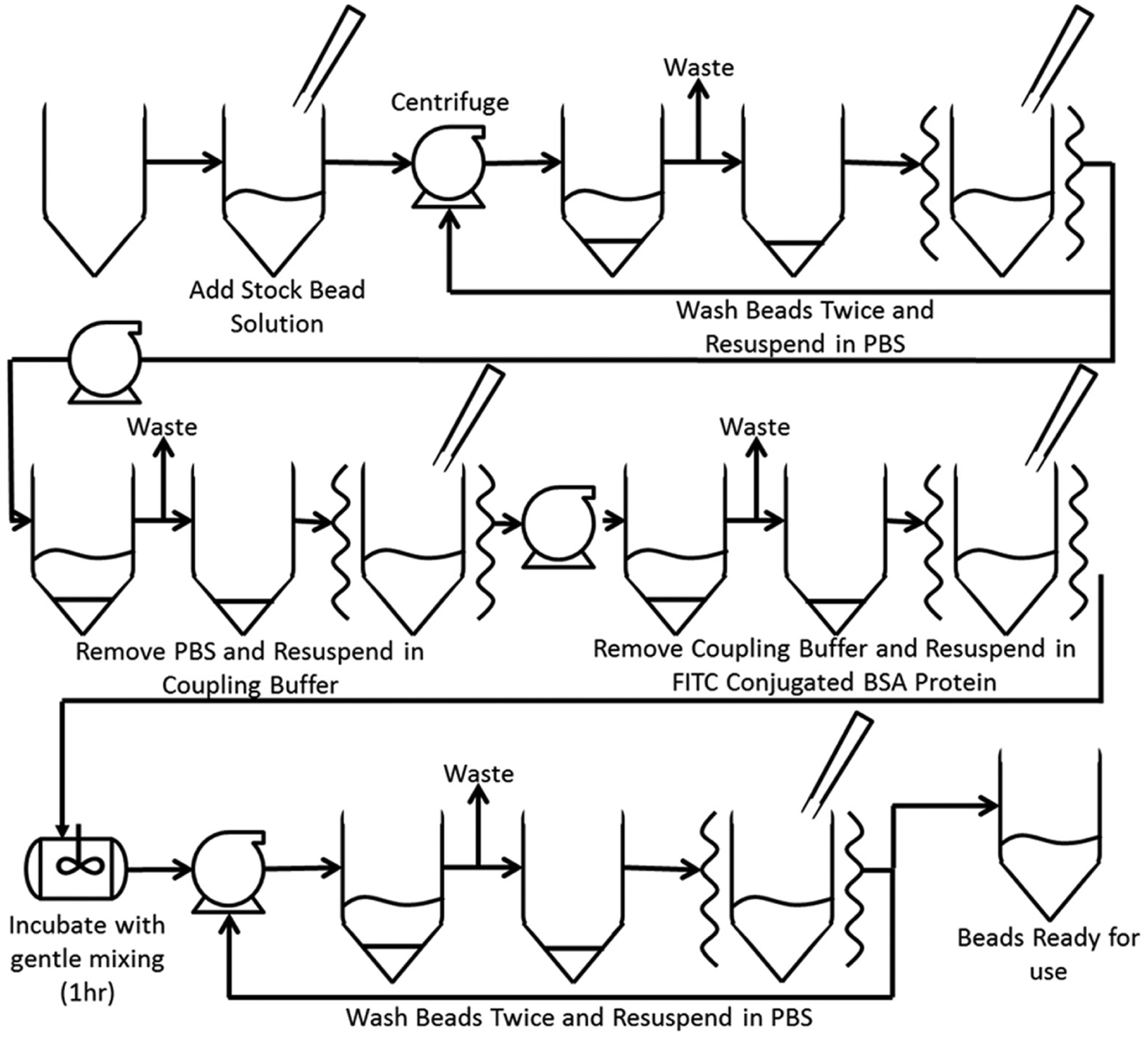
Manual functionalization process schematic. This image provides a pictographic representation of the manual functionalization of microbeads with fluorescein isothiocyanate–bovine serum albumin protein.
Robot Hardware Design
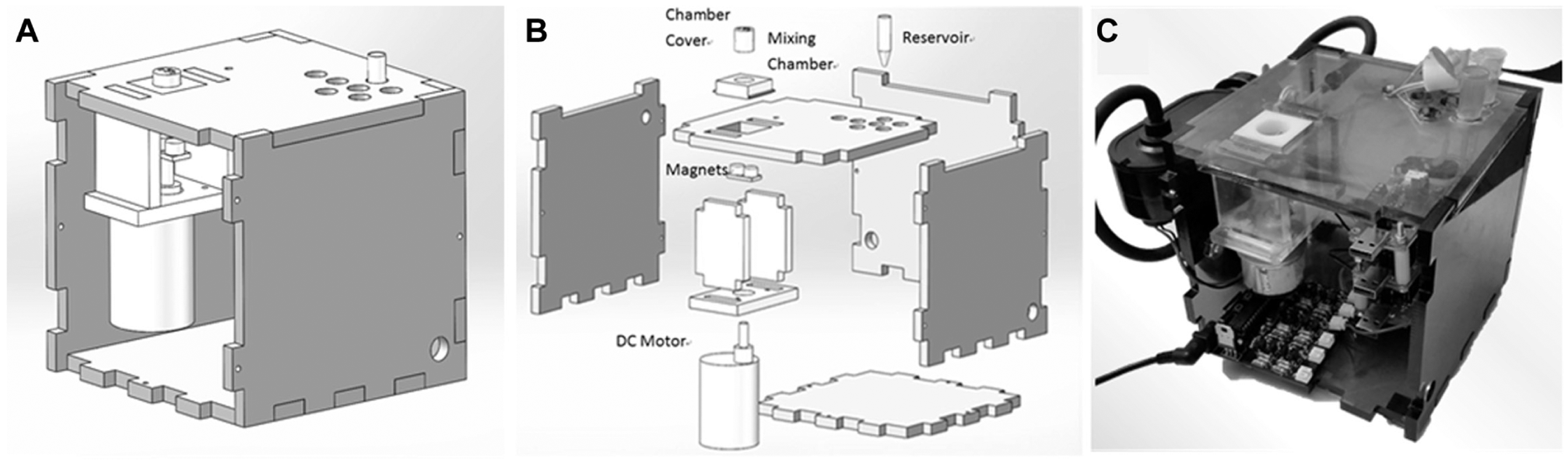
The robot is contained within a cuboidal acrylic structure machined with a laser cutter and occupies a total footprint of 16.9 cm2 with an overall volume of 2028 cm3 ( Fig. 3 ). The mixing chamber, a square post (640 mm2) with a concentric cylindrical vacancy (15 mm diameter), is cut into the top cover of the robot. A tube with an inner diameter of 1.5 mm and length of approximately 100 mm connects the bottom of the mixing chamber to the vacuum pump. A cylindrical cap comprises the mixing chamber cover and contains a concentric 12.3 mm vacancy. Friction firmly holds the cylindrical cap and the filter paper to the square post, forming a mixing chamber. Hence, the filter paper is easy to install and remove to collect the processed beads. Three tubes of equal diameter and length connect to the top of the chamber cover, each in line with independent micropumps that control the flow of reagent into the chamber. In addition, a 5 × 0.8 mm2 rectangular air vent on the chamber cover allows air into the chamber during liquid waste removal. This feature prevents the vacuum pump from extracting solutions directly from the reservoirs when eliminating waste material.
(
A 6 mm long cylindrical magnet used as a stir rod is housed in the mixing chamber to provide mechanical perturbations during solution amalgamation. A 12V DC motor operating at 200 Hz, connected to the bottom of the top cover of the robot frame, and two parallel vertical bar magnets, coupled to the stir rod, drive the mixing process. Two magnets connected to the DC motor drive shaft are attached to an acrylic plate and are responsible for driving the magnetic stirrer. The height of the motor was adjusted to optimize the force applied to the magnetic stirrer ( Fig. 4 ). Initial prototypes for this technology had attempted to implement a vortexing system to enable proper mixing within the reaction chamber, but because of complexities with friction generation, maintenance, and jostling of sensitive equipment; the final design used the magnetic stir bar system described above.
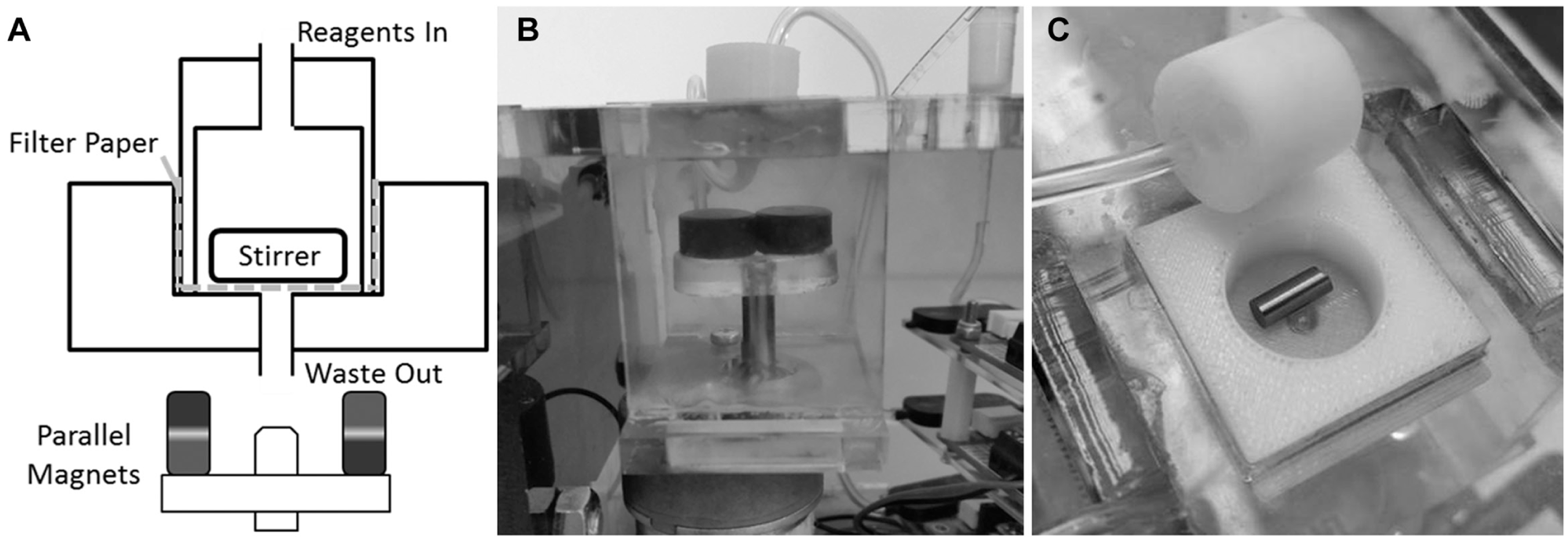
Mixing chamber and magnetic stir system. (
Electronics
The electronics used to control the device are centered on a custom printed circuit board (PCB). The PCB uses three main components to manipulate the actuators: an ATmega 328P-PU microcontroller; a Bartels Mikrotechnik mp6 pump controller that supplies a TTL square wave to drive the mp6 micropumps, and a set of single-pole double-throw relays to direct power to the three mp6 piezo micropumps. An image of the custom PCB schematic file and realized product has been provided with the
An Arduino microcontroller board with a 32 bit ATmega328 microcontroller chip is used to control all pumps and the stirrer motor. The board is powered via a 9 VDC barrel jack power supply. The system’s power either can originate from a 9 VDC battery or can be modulated from a 120 VDC wall outlet. Diodes are used within the circuitry to guarantee that all reverse bias voltages and currents remain small enough to inhibit potential damage. In future iterations of the technology, this system will be shifted to MOSFET protection, using an N-MOS component in the ground return path. 22
The robot uses three high-precision piezoelectric micropumps (Bartels Mikrotechnik mp6) with one-way check valves in series to pump liquid from the reagent reservoirs through each of the three reagent tubing lines into the functionalization chamber. The micropumps have several settings to control the frequency and amplitude of the AC piezoelectric actuation. Jumper pins allow the user to select from nine different frequency and amplitude combinations between 25 and 226 Hz and 85 and 270 Vpp, respectively, produced from onboard waveform generators. In this study, the frequency and amplitude of the voltage were set to 100 Hz and 235 Vpp, respectively.
Typical values for the rate of flow were measured at the listed maximum of 7 mL/min when on and at the listed minimum of 0 mL/min when off. 23 The mp6-EVA controller converts 5 VDC to 235 Vpp at 100 Hz with an upper current draw of 30 mA, which is used to drive the micropumps. Each micropump contains two piezoelectric actuators, with a 180° phase shift, formed into diaphragm pumps. A Molex to header connector joins the PCB and micropumps. Each of the three pumps requires four separate power connecters, resulting in a total of 12 power lines. The 12 power lines are connected to an array of 12 relays on the PCB, used to control the individual micropumps when the microcontroller sends the appropriate command. Four relays per pump are used due to an operational frequency cap of 100 Hz. By using one relay for each pump pin, the frequency is manipulated to yield expedited pump operation.
The system uses three mp6-EVA controller boards to independently drive the three mp6 micropumps. Power for the mp6-EVA is controlled by N-channel power MOSFET transistors. These transistors provide the constant 50 mA in order to stay open. This current supply is significantly higher than the maximum current that the ATmega microcontroller can deliver for a sustained period of time. The relays in turn deliver the 235 Vpp that the mp6-EVA generates to each mp6 micropump. Red LEDs are used to indicate which micropump is currently powered for visual feedback.
An integrated vacuum pump, modified from a Dorman 904-214 mechanical vacuum pump, is installed on the exterior of the acrylic structure and is used to remove waste liquid from the functionalization chamber through a polycarbonate filter after each functionalization step. The vacuum pump operates at approximately 10 psi and is controlled through the microcontroller. Tubing from the vacuum pump connects to the side of the mixing chamber through a custom three-dimensional printed manifold.
Components for Mixing
To facilitate rapid mixing of reagents with beads, the mixing chamber contains a magnetic stirring rod. A brushless 12V DC motor is embedded directly below the main mixing chamber. The motor has a perpendicular acrylic plate with two axially parallel, permanent bar-magnets offset from the center of rotation. The magnetic system is coupled to the magnetic stir rod, thus driving the mixing process. To ensure thorough mixing of beads with a given reagent, the distance between the motor and the mixing chamber as well as the shape and dimensions of the magnetic stir rod have been optimized to allow greater interaction between the stir rod and the parallel bar magnets ( Fig. 4 ).
Robot Software Design
The microcontroller is programmed to define the type of reagents from three prepared solutions, their respective flow rates, and their initial reservoirs. The microcontroller can also be programmed to dictate the volume of liquid injections, mixing speed and time, incubation time, and removal of waste liquids. The microcontroller is programmed using the Arduino IDE and bootloader to upload custom scripts to the microcontroller. Arduino IDE is a free software package that can be downloaded from arduino.cc.
Each pump signal from the program was mapped to a specified pin connected to a pump. The program specifies the parameters of the pulse width modulated (PWM) signal regulating the on-board relays. The PWM signal allows for precise control over both flow rates and fluidic pump system power. In addition, the user defines the order of pump activation and changes the duration of each command using the Arduino IDE by uploading new instructions via standard USB to the microcontroller.
Materials and Methods
Manual Bead Functionalization Protocol
Polystyrene microbeads (4 µm) were purchased from Bangs Labs. The microbeads were washed once in PBS. To facilitate the exchange of buffer solution, centrifugation at 2000g for 10 min was performed to sediment the beads. The supernatant was removed and the pellet of beads was resuspended in PBS inside a 2 mL centrifuge tube. The coupling buffer was prepared by dissolving 10.0 mg EDAC into 50 µL coupling buffer solution provided by the manufacturer (Bangs Laboratories PolyLink Protein Coupling Kit). The EDAC-coupling buffer was added to the microbeads according to the covalent coupling protocol provided by Bangs Laboratories. FITC-BSA was prepared at a concentration of 2 mg/mL and volume of 63 µL and added into the centrifuge tube in a darkened room. The microbeads were incubated for 1.5 h with the FITC-BSA. The microbeads were then washed twice in PBS via centrifugation and liquid exchange and resuspended in PBS. Fluorescence microscopy was performed to visually confirm functionalization of the microbeads. In addition, flow cytometry was performed to quantify the percentage of beads successfully functionalized with protein in comparison to the original quantity of microbeads at the start of the experiment. The flow cytometry data were gated to include fluorescence from individual beads and avoid clustered beads. Similar calculations and gates were used in the automated protocol analyses.
Automated Protocol
Polystyrene microbeads were loaded into the mixing chamber of the robot by pipetting onto a 0.5 µm pore filter paper placed at the bottom of the chamber. The chamber was then sealed by securing the top plate via tightening of screws. The PBS wash, EDAC-coupling buffer, and the prepared FITC-BSA protein solution were added into the three reagent wells. The robot was set to run twice separately for 1 h and 1.5 h. After completion of the protein functionalization process, the mixing chamber was opened and the filter paper removed. The accumulated microbeads were washed from the filter paper and resuspended in PBS. The filter paper was further sonicated for 60 s in PBS to facilitate removal of any remaining microbeads. Fluorescence microscopy was performed to visually confirm functionalization of the microbeads. Flow cytometry was performed to determine the percentage of successfully functionalized microbeads. In addition, plate reader analyses were performed to quantify the fluorescence of 1.5 h mixed beads. Both prior to and following completion of the robotic methodology, a wash procedure was executed in the reservoirs and channels that experienced a change in material. This procedure included a 5 min prewash cycle with a diluted cleaning agent followed by a 5 min rinse with a buffer. After experimentation, the system is cleaned again with a diluted cleaning agent followed by a buffer solution rinse at 10 min each.
Results
Both the manual and automated methods successfully produced functionalized microbeads. FITC-BSA functionalization was visually confirmed via fluorescence microscopy ( Fig. 5 ). Automated FITC-BSA functionalization of beads (1.5 h) was also quantitatively determined via plate reader. The fluorescent protein resulting from the automated method was uniformly distributed on the microbeads for the vast majority of beads examined.
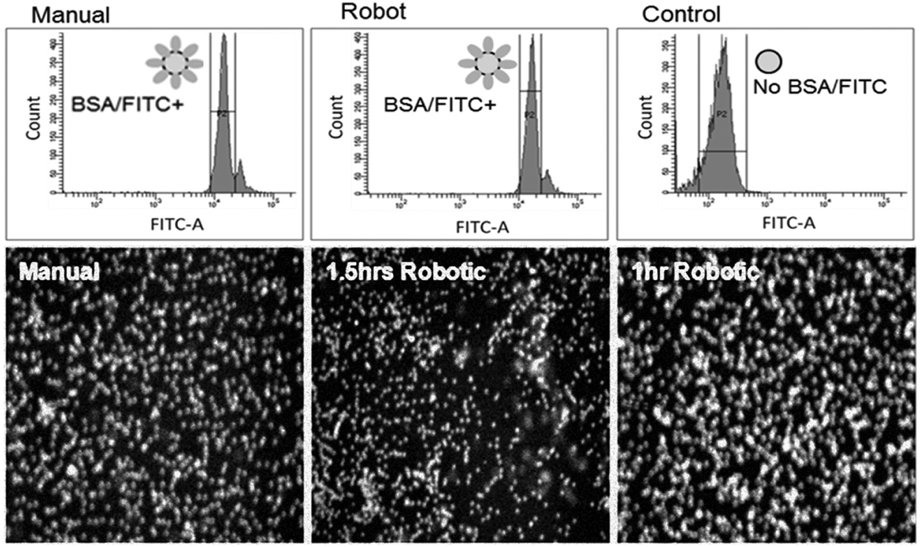
Flow cytometry analysis showed that the manual method trials (n = 2) successfully functionalized 92.4% ± 5.9% of microbeads; the automated method trials (n = 3) successfully functionalized 91.3% ± 3.8% of microbeads. Fluorescence control bead sets, in which no fluorescein isothiocyanate–bovine serum albumin (FITC-BSA) was added to the protocol, revealed fluorescence intensity levels two orders of magnitude less than the positive sample. Fluorescent microscopy results confirm surface functionalization. The 20x bright field and 20x FITC fluorescence imaging of 2 µm beads prepared through the manual and robot methods at two different conjugation times. (Fluorescence intensity data for beads processed without EDAC-coupling buffer can be found in the
The manual method of functionalization required approximately 3 h to complete as opposed to 2 h for the robot. Automated microbead functionalization for 1 h was also successful, indicating that the robotic methodology can execute the conjugation process in a shorter time frame with fewer resources ( Fig. 5 ). This implies that further optimization of the robotic system is possible. The automation increases the speed of several manual steps, particularly the pipetting and buffer exchange; moreover, the amount of active operator time is substantially reduced.
Discussion
The functionalization robot successfully automates the covalent coupling of microbeads with proteins. The device performs liquid handling to sequentially activate the bead surface, remove the activating chemical, add proteins to the bead solution, and thoroughly mix the solution so that proteins uniformly attach to the beads. Waste product is also appropriately managed and disposed of as needed throughout the protocol steps.
Using this automation scheme, user-based bottlenecks and sources of error are avoided, particularly during centrifugation, manual vortexing, and manual pipetting. Through refinement, the automated method can further improve reproducibility through reduction of user error. Although the consumable costs were 30% higher due to reagent loss through tubing, future designs can minimize volume loss by decreasing the spacing between the reservoirs and mixing chamber and reducing tubing diameter. Better component integration and miniaturization through microfabrication techniques can also be explored but need to be weighed against cost of production.
The results of the automated functionalization process were similar to the results of the manual process by an experienced user. A two-tailed T-test (p = 0.8116, α = 0.05) indicates the percentage of functionalized beads was not significantly different between the robot and manual methods. However, because the robotic method requires pointedly less active user time, it is more time efficient. In addition, a lower percentage of beads using the robotic method are lost (<5%), in comparison to the manual method (>10%). The higher loss in the manual method is possibly a result of enhanced sticking of beads to the container walls or pipet tips.
This simple, automated method to functionalize microbeads is an important approach to prepare beads with limited human time and attention. Functionalization with FITC-BSA is a relatively simple functionalization process, and over several repetitions, the total time saved by researchers can be enormous. Future robots can also be designed for more complicated functionalization processes, including attaching multiple proteins to Janus particles,3,8 modifying the system for solid phase synthesis, or functionalizing cells. In the case of clinical environments, using the robot to functionalize cellular samples with antibody or chemical labels can also prove highly valuable.
In future studies, incorporation of temperature control and pH readout will improve the reliability of the functionalization process. To implement this temperature feedback system, the automated functionalizer would require a thermocouple, thermistor, or other temperature-measuring technology, as well as a cooling and/or heating unit. Once this technology is installed within or near the reaction chamber, temperature control becomes entirely software based, easily implemented in addition to, or parallel with, the preexisting code on the microcontroller. Furthermore, thermal isolation from the surrounding environment through insulation may provide more accurate temperature control.
Additional challenges in future designs include decreasing the volume of reagents lost by the system, increasing the number of reagents that can be handled by the system, improving the mixing system to include vortexing as a replacement for magnetic bar stirring, and increasing the efficacy of covalent coupling within the system. Miniaturization and component integration will assist with this process.
In this experiment, the proof of concept for using a robot to automate microbead functionalization was demonstrated. The robotic method, used to bind FITC-BSA protein to polystyrene microbeads, was tested against a manual method executed by trained laboratory technicians. With fluorescent microscopy and flow cytometric analyses, we determined that the automated method was equally effective at bead functionalization compared with a manual method. The primary advantage of the robot, however, is the removal of several laborious steps that reduce the overall process time. The total time of active labor to functionalize FITC-BSA to microbeads was reduced from 2 h to 10 min per experiment. With adjustment of some operating parameters and improvement to the robotic system, a similar design can be developed to attach biomolecules to cells. The introduction of this device in academic laboratories will open up a variety of new experiments in particle functionalization.
Footnotes
Declaration of Conflicting Interests
The authors declared no potential conflicts of interest with respect to the research, authorship, and/or publication of this article.
Funding
The authors received no financial support for the research, authorship, and/or publication of this article.
References
Supplementary Material
Please find the following supplemental material available below.
For Open Access articles published under a Creative Commons License, all supplemental material carries the same license as the article it is associated with.
For non-Open Access articles published, all supplemental material carries a non-exclusive license, and permission requests for re-use of supplemental material or any part of supplemental material shall be sent directly to the copyright owner as specified in the copyright notice associated with the article.