
Abstract
A contact closure system was constructed that uses two contact closure sender boards that communicate wirelessly to four contact closure receiver boards to distribute start signals from two or three liquid chromatographs to 14 instruments, pumps, detectors, or other components. Default high, closed low, TTL logic (5-volt) start signals from two autosamplers are converted to simple contacts by powered relay boards that are then connected to two 16-channel wireless contact closure sender boards. The contact closure signals from the two sender boards are transmitted wirelessly to two pairs of eight-channel receiver boards (total of 32 contact signals) that distribute the start signal to 14 switches that allow selection of which start signal is sent to which instrument, pump, or detector. The contact closure system is used for quadruple parallel mass spectrometry experiments in which four mass spectrometers, using three different atmospheric pressure ionization modes, plus a UV detector, an evaporative light-scattering detector, a corona charged aerosol detector, and two syringe pumps supplying electrolyte, are all synchronized to start simultaneously. A wide variety of liquid chromatography–mass spectrometry experiments using multiple liquid chromatographs and mass spectrometers simultaneously, LCx/MSy, including column-switching experiments, can be reconfigured simply by toggling switches.
Introduction
The three types of atmospheric pressure ionization (API) techniques most commonly used to couple liquid chromatography (LC) to mass spectrometry (MS) are electrospray ionization (ESI), atmospheric pressure chemical ionization (APCI), and atmospheric pressure photoionization (APPI). Each of these offers benefits relative to the others; ESI mass spectra are different and complementary to mass spectra obtained from APCI and APPI, and API techniques often show differences in response to different classes of molecules. Because of this, it is often desirable to obtain data from multiple API techniques for the same molecules. Hundreds of articles in the literature describe sequential analyses obtained by conducting an experiment using one API technique, changing the ionization source, and rerunning the experiment using a different API technique. In addition to mass spectrometry, it is often beneficial to acquire data from a UV detector, which can be more sensitive than MS detection. Other popular techniques for LC detection include use of an evaporative light-scattering detector (ELSD) or a corona charged aerosol detector (CAD), which act as “universal detectors” that do not depend on absorption by a chromophore.
In 2011, the first demonstration of “triple parallel MS,” which used ESI-MS and high- and low-sensitivity APCI-MS (for analysis of minor components and bulk components, respectively) simultaneously, along with UV, ELSD, and corona CAD detection, for six detectors overall, was reported. 1 Since this experiment used one LC and three mass spectrometers, it is referred to as an LC1/MS3 experiment. In 2013, further advancements were made with the first report of “quadruple parallel MS,” which employed the six detectors above plus APPI-MS, for seven detectors overall. 2 This is referred to as an LC1/MS4 experiment. Results for quantification by various techniques using 2D and 3D detectors were compared and contrasted using disparate techniques (UV, ELSD, CAD, and MS).
Automation of experiments such as these (allowing sequences to run unattended over several days) requires coordination and synchronization of the start signals on all instruments participating in the experiment, plus syringe pumps supplying electrolyte to the ESI-MS instrument and, potentially, the dopant pump supplying dopant to the APPI-MS instrument. For the reports above, a contact closure (CC) manifold was constructed that allowed the CC signal from any of three liquid chromatographs to be selected and distributed to any of the desired detectors. The distribution manifold was flexible enough to allow subsets of instruments to be started using any of the three LCs and also allowed column-switching experiments, in which one LC could start another LC for synchronized starts in LC2/MSy experiments, such as the LC2/MS2 experiment reported in 2003. 3
Unfortunately, the distribution panel used in those experiments1,2 had the disadvantage that all connections were hardwired together, so when a syringe pump board failed due to repeated power outages, it caused a CC error that propagated through the whole system and rendered it no longer usable. When that one component failed, the other components would not remain in the “waiting” condition without starting prematurely. Similarly, if some components were powered off, other components would not remain in the waiting state. Furthermore, having all components hardwired together had the potential to pass an overvoltage on one component to other components, leading to other potential board failures. Repeated power outages and potential damage to components caused us to implement an improved, more robust, wireless CC distribution system. It was important, however, to maintain all of the functionality of the previous system, while implementing an improved system in which each instrument that produced or received a CC was electrically isolated from other components to provide a degree of protection to all components.
Described here is an updated CC distribution panel that allows the CC start signals from three LC autosamplers (ASs), plus a momentary CC test, to be distributed to other components, pumps, or detectors. This provides an extremely versatile distribution manifold that allows instruments participating in LCx/MSy experiments to be reconfigured by switch selection, without any hardwire changes. The CCs from two LC ASs (easily expandable to three) are attached to two 16-channel wireless communication senders that communicate with two sets of two wireless receivers attached to the CC distribution panel. A set of switches allows two sets of CCs to be distributed to any combination of detectors, pumps, analog-to-digital converters, and other components.
Materials and Methods
Sixteen medium-duty (10-Amp) double-pole, double-throw (DPDT) center off (CO) switches (66-1624; Coastal Electronics Supply, Houma, LA) were ordered from an online supplier. Two 15-Amp, 12-volt two-input relay boards (RLY102-12V-FT) were ordered from Winford Engineering (Bay City, MI). Two wireless CC systems, each consisting of one 16-channel wireless sender board with two 8-channel receiver boards (MirM85), 12 VDC 1.25-Amp power supplies (PWR12), and plastic enclosures (2-SR171B), were ordered from Relay Pros (Osceola, MO). Each wireless contact closure receiver board (WCCRB) had eight 5-Amp single-pole, double-throw relays. Normal speaker wires in various gauges (18, 20, and 22 gauge) were purchased from local electronics supply stores.
Components were mounted to Herman Miller (Zeeland, MI) laboratory furniture components. The two sender boards with conversion relays were mounted on 12.5 × 7.5–inch shelf-end pieces, the receiver boards were mounted to the bottom of a wire chase, and switches were mounted in the front side of the same wire chase. Miscellaneous other components, such as ¾-inch board mounting stand-offs and machine screws, were scavenged from supplies in the laboratory.
Results and Discussion
Powered Relays and Sender Boards
Each wireless sender board communicates with its mated pair of receiver boards using the 802.15.4 wireless protocol. They communicate only with the mated boards, and the two systems do not interfere with each other, because the communication is coded with the board serial numbers (personal communication with Relay Pros technical staff, Nov. 6, 2013). The outputs from the Agilent Technologies (Santa Clara, CA) ASs in the LC systems are 5-volt TTL logic default high, start signal low, signals. The CC sender boards require zero voltage simple CC inputs, or damage to the sender boards will occur. Therefore, the voltages from the ASs were converted to simple CCs using the two-input RLY102-12V-FT powered relay boards (PRBs). The current from the TTL logic AS outputs was not sufficient to switch nonpowered relay boards (not shown) that we ordered and tested, so self-powered relay boards were used. The 12-volt powered relays (instead of 5-volt versions) were selected so they could be powered using the same power supply as the wireless sender board. Figure 1 shows the PRBs and wireless contact closure sender boards (WCCSBs) mounted to shelf-end pieces that slide-mounted into Herman Miller frames.
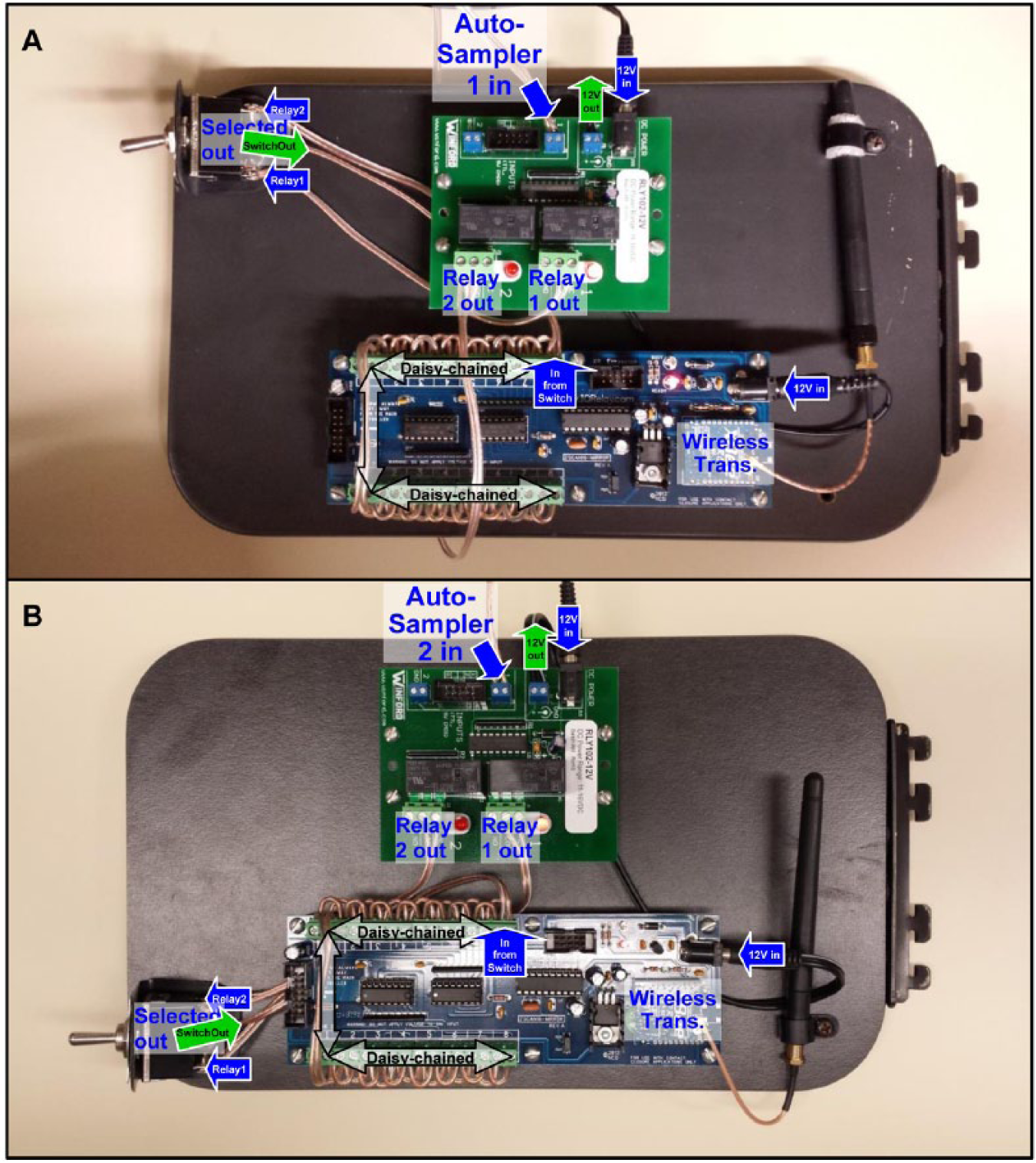
Voltage conversion relay boards and contact closure sender boards mounted on movable shelf-end pieces. (
The number of power supplies (PSs) required for the system was minimized by connecting boards together using terminal screw connections. The 1.25-Amp PSs for the WCCSBs were first attached (top of Fig. 1A,B ) to the PRBs (instead of the 0.4-Amp PSs ordered with the PRBs), and the ends of scavenged PSs, with the proper barrel connector size, were cut off and connected from the terminal screw outputs of each PRB (blue terminals next to barrel input connectors, top of Fig. 1A,B ) to the PS barrel input connectors of the WCCSBs (middle right of Fig. 1A,B ).
For maximum flexibility and expandability, two-channel PRBs were used. The ASs were each connected to one switch input, from pins 1 (ground) and 3 in the AS nine-pin “remote” connections, and the second inputs were used for at least three options, described below. DPDT CO switches, mounted via improvised plastic “L” brackets, were used to select which inputs from the PRBs were directed to the WCCSBs. The two outputs of the PRBs were connected as inputs to the two opposite end pole sets of the DPDT CO switches, and the center poles of the switches acted as the outputs that were sent to the inputs of the WCCSBs. The outputs of the #1 relays were connected to the “normally closed” (NC) terminals (no voltage applied) of the relays. Since the ASs were normally TTL high (5 volt applied), it caused the relay to be in an activated state (red LEDs lit), which was open when output connections were made to the NC terminals. Then, when a start signal was initiated, it caused a low condition and the voltage was reduced, and the relay went to the NC position, which caused a closure of that relay contact (no voltage, closed position). In other words, the AS normally applied a voltage and held relay 1 open, and when voltage was taken away, that relay closed.
One application of PRB relay 2 was as a manual CC, for testing and immediate starts. For this application, pictured in Figure 1B , there was no connection to the second input of the PRB (top left blue terminal of Fig. 1B ), so the connection from the selector switch to the NC position of that relay (green terminal 2, middle left of Fig. 1B ) resulted simply in a contact closed condition.
A second application of PRB relay 2 was to use the relay board in each AS, instead of the normal TTL start signal, since our ASs were fitted with optional relay boards (G1351-68701). While not required, the advantage of this is that the duration of the CC can be programmed in LC methods. Our methods include a timetable to close the AS contact at 0.01 min, held to 0.1 min, and returned to the open position, for a 5.4-s duration. The optional AS relay boards perform the same function as the PRBs, so no voltage is present. Pins 1 and 2 from the 15-pin AS external contact connector were connected to the PRB relay 2 normally open (NO) terminal position (middle left, Fig. 1A ), via a scavenged 15-pin serial connector cutoff and connected to 22-gauge speaker wire (or Agilent cable G1103-61611 can be used). Switch position 2 was also connected to the PRB relay 2 NO terminal, so signal from this relay terminal was sent to the WCCSB when the switch was in the down position.
A third application of the PRB relay 2 allows the AS from an older Thermo Separation Products (TSP; San Jose, CA) system in our laboratory to participate in experiments. The TSP AS3000 AS provides 5-volt TTL logic output for the inject signal that is inactive low, active high by default, which can be changed in the AS configuration. In its default configuration, the output from the AS would be connected to input terminal 2 (blue terminal, upper left of Fig. 1B ) of WCCSB 2, and the PRB relay output 2 (green terminal, middle left of Fig. 1B ) to the switch would be changed from the NC terminals to the NO terminals. In this application, the TSP AS would be selected by toggling the switch to the down position. Wired in this way, the TSP system could be used in combination with the Agilent 1200 system (on WCCSB 1) in LC2/MSy experiments, whereas if the TSP AS were instead similarly wired to WCCSB 1, it could be used in combination with the Agilent 1290 system on WCCSB 2.
Since we wanted all attached instruments to start simultaneously from a single AS start signal, all terminals on the WCCSBs were “daisy-chained” together, and bank 1 was connected to bank 2, causing the signal from the switch to activate all CCs simultaneously. Alternating terminals 1, 3, 5, 7, 9, 11, 13, and 15 and terminals 2, 4, 6, 8, 10, 12, 14, and 16 were connected by short pieces of wire, as pictured in Figure 1 . Finally, the antennae were mounted using plastic clips, with or without foam padding, as necessary.
Receiver Boards and Contact Distribution Switches
The two pairs of WCCRBs were mounted in plastic enclosures attached with two screws to the bottom of the wire trace ( Figs. 2 and 3 ). Holes were drilled into the wire trace, seen in Figure 2 , to allow the output CC relays to be connected to the source selection switches mounted in the front face of the wire trace by means of 22-gauge wires. Only 14 of 16 available CC outputs are currently in use, leaving two for future expansion. Another hole was drilled above each WCCRB to allow the 12-volt PS from one receiver board to be connected to the mated board by 18-gauge wire connected to the auxiliary power terminals (green terminals, lower middle of Fig. 2 ). Enclosures were drilled to accommodate the antennae and PSs, and the tops were notched to accommodate the wire connections. The up positions of 14 switches were hardwired to the two WCCRBs on the right side of the wire trace ( Fig. 3 ), which receive their signals from WCCSB 1 attached to the Agilent 1200, and the down positions were hardwired to the two WCCRBs on the left side of the wire trace, which received their signals from WCCSB 2 attached to the Agilent 1290. The output of each selector switch had a short piece of 22-gauge wire with bullet connectors on the end for distribution to the receiving components.
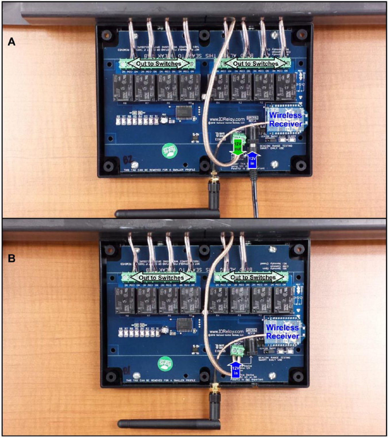
Contact closure receiver boards mounted on removable wire trace. (
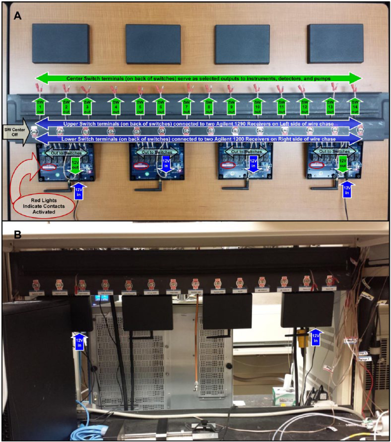
Contact closure receiver boards mounted on removable wire chase. (
The first three switches were then connected to the start inputs on the back of the Agilent 1200, Agilent 1290, and TSP pumps. This permitted any of the autosamplers to start any of the pumps, allowing up to LC3/MSy experiments or any combination of LC2/MSy experiments. The next four switches went to the four mass spectrometers currently used in our quadruple parallel MS experiments. The next three switches were attached to the SS420X analog-to-digital converter, corona CAD, and ELSD. The next two switches were attached to AB140B dual-piston syringe pumps, which caused them to coordinate the refilling of the pumps with the start of each run in a sequence (we typically use 35-run sequences). The last two switches have not yet been connected and remain available for expansion.
Although the WCCSBs communicate wirelessly with the pairs of WCCRBs ( Fig. 4 ), the connections from the WCCRBs through the switches to the receiving pumps, instruments, detectors, and other components are wired. Prior to connection of all the switches to the receiving components, the WCCRBs were tested in a room down the hall from the laboratory and found to be able to receive the start signals from the WCCSBs with no difficulty ( Fig. 3A ). This was done purely to test the ranges of the WCCRBs. In actual experiments, all instruments are located in the same room.
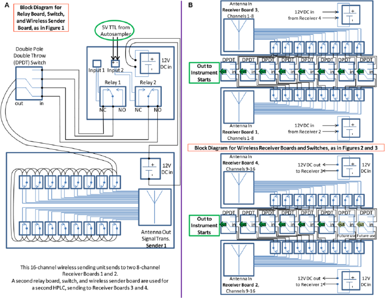
Block diagram showing (
In conclusion, described here is a partially wireless CC system that employs wireless communication from 16-channel WCCSBs attached to a switch-selectable choice of ASs or a manual closure for testing or immediate start through PRBs that convert TTL logic signals to simple CCs. The CC signals transmitted wirelessly are received by mated pairs of eight-channel WCCRBs that do not interfere with each other and distribute CC signals to a switch-selectable variety of pumps, mass spectrometers, detectors, and other components. This new partially wireless CC distribution system allows a wide variety of LCx/MSy experiments to be conducted in which one LC starts up to four mass spectrometers and three other detectors (UV, CAD, and ELSD), for seven detectors overall, in quadruple parallel mass spectrometry (LC1/MS4) experiments, shown in Figure 5 , or in which subsets of detectors can be simultaneously used for separate runs initiated by separate LC systems (e.g., LC1/MS2 + LC1/MS2) or for column-switching experiments in which an injection on one LC system starts a second LC system, each with two mass spectrometers attached, with multiple combinations of other detectors, in an LC2/MS4 experiment, where an electronic switching valve switches a bolus from one LC system to the other. The fact that this updated and improved system provides wireless communication and electrical isolation of all CC signals makes it more advanced and robust than the hardwired system that we have used in the past.
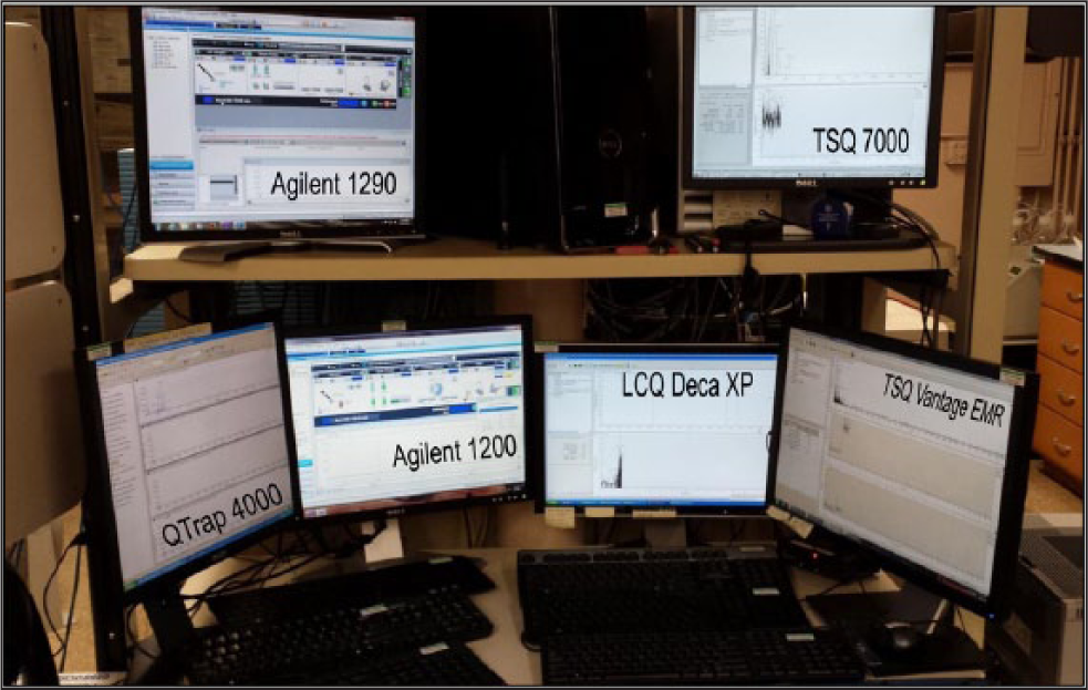
Data acquisition station for quadruple parallel mass spectrometry (LC1/MS4) experiment started by the partially wireless contact closure (CC) system. Instruments started from wireless CC: upper left: Agilent 1290 (Agilent Technologies, Santa Clara, CA) liquid chromatography (LC) system; upper right: TSQ 7000 (San Jose, CA) mass spectrometer; lower left: QTrap 4000 (Framingham, MA) mass spectrometer; lower center left: Agilent 1200 LC system with UV, charged aerosol detector (CAD), and evaporative light-scattering detector (ELSD); center right: LCQ Deca XP (San Jose, CA) mass spectrometer; lower right: TSQ Vantage EMR (San Jose, CA) mass spectrometer with CAD and ELSD on an SS420X analog-to-digital converter. Agilent 1290 supplying acetone dopant at 10 µL/min started by the Agilent 1200 autosampler for demonstration purposes, with all others performing data acquisition.
Footnotes
Acknowledgements
Mention or use of specific products or brands does not represent or imply endorsement by the USDA.
Declaration of Conflicting Interests
The author declares no potential conflicts of interest with respect to the construction of this apparatus, authorship, or publication of this article.
Funding
The author disclosed receipt of the following financial support for the research, authorship, and/or publication of this article: This work was supported by the USDA Agricultural Research Service.
References
Supplementary Material
Please find the following supplemental material available below.
For Open Access articles published under a Creative Commons License, all supplemental material carries the same license as the article it is associated with.
For non-Open Access articles published, all supplemental material carries a non-exclusive license, and permission requests for re-use of supplemental material or any part of supplemental material shall be sent directly to the copyright owner as specified in the copyright notice associated with the article.