
Abstract
We present a novel method to fragment DNA by using lateral cavity acoustic transducers (LCATs). DNA solution is placed within a microfluidic device containing LCATs. The LCATs cause microstreaming, which fragments DNA within the solution without any need for purification or downstream processing. The LCAT-based DNA fragmentation method offers an easy-to-use, low-cost, low-energy way to fragment DNA that is amenable to integration on microfluidic platforms to further automate DNA processing. Furthermore, the LCAT microdevice requires less than 10 µL of sample, and no external equipment is needed besides a piezoelectric transducer.
Introduction
The need for small DNA fragments for assays and diagnostic purposes requires a DNA fragmentation method that is simple to use and easy to integrate into a system. DNA obtained from a sample needs to be prepared in such a way that it can readily hybridize with probes complementary to a gene of interest. Therefore, DNA should be fragmented to sizes similar to probes to ensure hybridization and sensitivity.1,2 By moving DNA fragmentation to a chip platform, sample volumes can be reduced, which will lower the overall process cost. However, the methods currently available are not designed to be integrated on chip.
Current DNA fragmentation methods include hydrodynamic shearing,1,3,4 enzymatic digestion, sonication/ultrasound,2,5 and nebulization.6,7 None of these methods have been conducive for integration onto microfluidic chips for a fully automated system of sample preparation and analysis. Hydrodynamic shearing entails pushing DNA solution through an orifice or constriction, which subjects the DNA to a velocity gradient between the main channel and the constriction channel, causing the DNA to fragment.1,3,4 Three issues hindering microfluidic, chip-based hydrodynamic shearing include external pump requirement, large sample volumes, and difficult device fabrication. Oefner et al. 3 cycled DNA through a 0.0025″ ID PEEK tubing at various flow rates ranging from 0.1 mL/min to 8.6 mL/min. Depending on the flow rate, they were able to control the size of the fragmented DNA but required 50 or 100 µL of sample to circulate through their system. 3 Recently, Shui et al. 1 fabricated a microfluidic chip to fragment DNA by flowing DNA at low flow rates through constrictions that were fabricated from glass (Borofloat) substrates. Glass chip fabrication poses the problem of low etch rates and also requires good sealing between the two layers and between the pump and chip connectors. Both of the hydrodynamic shearing–based systems would require dead volume of solution in the pump and the connectors to pump the fluid through an orifice, which would be problematic when there is little sample volume (less than 10 µL). Another method to fragment DNA includes enzymatic digestion, which uses restriction enzymes, but there is bias caused by some DNA having few sites for restriction enzymes as well as the need for purification if down processing is required.1,4 In addition, the enzymes require optimum conditions such as the correct pH and ionic strength. 2 Methods using ultrasound requires the use of a sonicator tip or a sonoreactor.2,5 Ultrasound, which consists of acoustic waves (20 kHz and higher), fragments DNA through stable and inertial cavitation.2,5,8 In solution, ultrasound causes cavitation or the formation of microbubbles from gases dissolved in the fluid. These microbubbles can oscillate and create microstreaming as well as collapse, both of which generate enough shear stress to fragment DNA. 2 However, both the sonicator tip and sonoreactor are large devices that cannot be used on chip and also require a large sample volume. Nebulization, which aerosolizes the DNA solution, poses the problem of postfragmentation collection and also the difficulty of automation. 6
Liu et al. 9 developed a micromixer based on cavitation microstreaming that requires only a piezoelectric transducer, which can be reused repeatedly. Cavitation microstreaming occurs when an air bubble undergoes oscillations in a fluid, creating velocity and pressure fluctuations in the surrounding fluid ( Fig. 1 ). 10 The oscillating bubble creates flow in the Stokes layer, which is on the order of 10 µm in size.10,11 Outside of the Stokes layer, the streaming is generated by the secondary vortices, which are driven by the slip condition at the boundary.10,11 The secondary streaming is what is seen in the bulk fluid, which can be used for various applications. The frequency and amplitude of the sound field affect the mode of oscillation of the air-liquid interface, which affects the streaming near the bubble.10,12 The micromixer consists of cavity acoustic transducers (CATs), which are dead-end channels that are placed inside of a chamber or channel, which trap air when a fluid is flowed over the cavities. The application of CATs can be changed depending on the placement of the CATs within a channel, either laterally (lateral cavity acoustic transducer [LCAT]) or vertically (vertical cavity acoustic transducer).9,13–16 CATs have been shown to be useful for various applications, such as pumping, 14 cell lysis, 17 switching, 13 and mixing.9,15,16 In this article, we describe a method using cavitation microstreaming in a microfluidic format to fragment human genomic DNA. LCATs placed along the sides of a microchannel are able to fragment DNA while requiring only a piezoelectric transducer, which can easily be integrated on chip. The LCAT device has no issue of dead end volumes and requires small volumes (less than 10 µL) to fragment DNA from greater than 50 kbp to less than 10 kbp within minutes. The LCAT method of fragmentation eliminates the need for bulky external equipment or down processing because no additional reagents are added to the solution, which make it amenable for DNA processing automation.
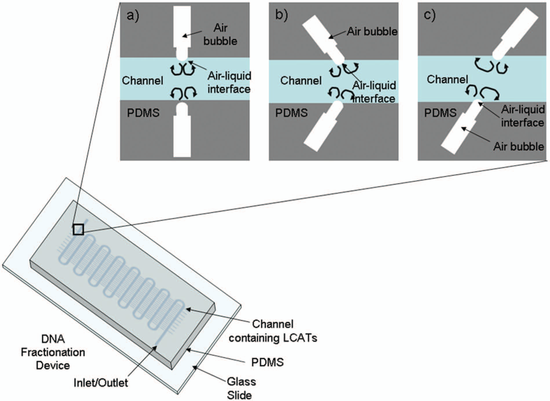
Cavitation microstreaming and devices. The three different configurations with inset of schematic of an lateral cavity acoustic transducer. Cavitation microstreaming is shown, which occurs when an air-liquid interface is excited due to a piezoelectric transducer. (
Materials and Methods
Reagents
Human genomic DNA (Cat. No. G3041) was purchased from Promega (Madison, WI), and a 1 kb plus DNA ladder (Cat. No. FERSM1334) was purchased from Fisher Scientific (Waltham, MA). TE buffer (Cat. No. 93302, 500 mL) purchased from Sigma-Aldrich (St. Louis, MO) was used to dilute human genomic DNA 5× to a concentration of 100 ng/mL and to load DNA onto the microfluidic devices. The human genomic DNA purchased from Promega is longer than 50 kbp.
Microfluidic Device Fabrication
Standard soft lithography is used to fabricate the devices. 18 The master mold fabrication consists of a one-step SU-8 process in which SU-8 2050 (Microchem, Newtown, MA) is spun on a silicon wafer to create the channels and LCATs of the device. The mold is developed using standard SU8 procedures. Briefly, a mask printed on transparency film (CADArt) is placed over the SU8 2050 layer, and the SU8 2050 and silicon wafer are UV exposed (AB&M UV flood exposure system). The mold is developed in SU8 developer (Microchem). After the SU8 mold fabrication, PDMS (1:10 mixing ratio Sylgard 184 Silicone Elastomer Kit; Dow Corning, Midland, MI) is then poured onto the mold and allowed to cure overnight. The PDMS device is then peeled off the mold, the inlet and outlet are created, and the device is then plasma bonded onto a glass slide using air plasma. The channel and LCATs in all devices are 50 µm in height. The schematic representation of the LCAT device is shown in Figure 2 . The channel width is 500 µm. The LCATs are 150 µm wide and 1 mm in length. Necks that are 90 µm wide and 50 µm long are placed on LCATs for uniform formation of the air-liquid interface.
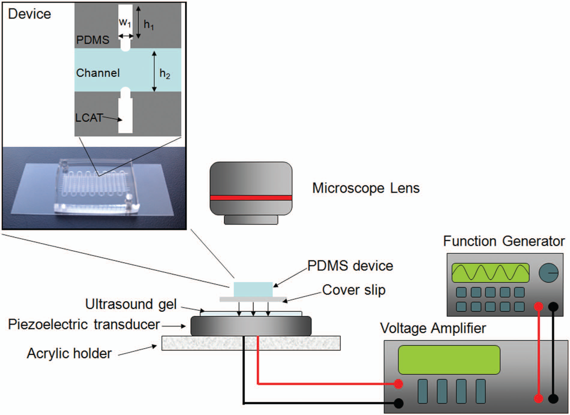
Lateral cavity acoustic transducer (LCAT) device setup schematic. The piezoelectric transducer is connected to a voltage amplifier and function generator. In the inset is a mixer configuration device made out of PDMS and a coverslip as well as two LCATs in the device with the channel filled. The LCAT height is 1 mm (h1) and width is 150 µm (w1). The height of the LCAT neck is 50 µm, and the width of the LCAT neck is 90 µm. The channel width is 500 µμm (h2).
LCAT Shearing
A piezoelectric transducer (Steminc SMD43T105F200S) is used to shear DNA. DNA solution is pipetted into the inlet of the microfluidic device and the DNA solution vacuumed pulled into the channel. To ensure there is minimal loss of signal transmission, the microfluidic device is placed over the piezoelectric transducer after ultrasound gel (Aquasonic 100) is applied between the PDMS device and the piezoelectric transducer. Lead wires from the piezoelectric transducer are connected to an amplifier (Krohn_hite model 7500 amplifier), which is connected to a function generator (Agilent 33220A) ( Fig. 2 ). The function generator is programmed to output a square wave at 49.3 kHz, the resonant frequency of the piezoelectric transducer, at various voltages of 10 to 30 Vpp. The DNA is then vacuumed pulled to the outlet, where a pipette is used to collect the DNA solution after fragmentation.
Agarose Electrophoresis
DNA samples were loaded and separated on a 1% agarose gel (UltraPure Agarose; Invitrogen, Carlsbad, CA) and run in TAE buffer that was diluted 10 times (UltraPure 10× TAE Buffer; Invitrogen). Ten microliters of SYBR Safe dye (1:10,000 dilution) purchased from Invitrogen was added to the gel prior to being poured into a gel casting tray and left to polymerize. Five microliters of sample was loaded into each lane, and separation was carried out at a constant voltage of 100 V for approximately 30 to 40 min. The gel was imaged using the BioRad Imager Universal Hood II. The intensity or brightness of the gel bands was measured using ImageJ, and the percentage of DNA was calculated using MATLAB. A line profile for each lane was taken using ImageJ. First, the background was subtracted from the gel image using ImageJ’s subtract background method. The line was then drawn down the center of the lane, and the intensity or brightness of each pixel along the line profile was measured. The amount of DNA was quantified in the band by measuring the area under the peak of the intensity profiles. The DNA yield present at a certain size band was calculated by dividing the area of the peak by the area underneath all peaks for that particular line profile using MATLAB.
Results and Discussion
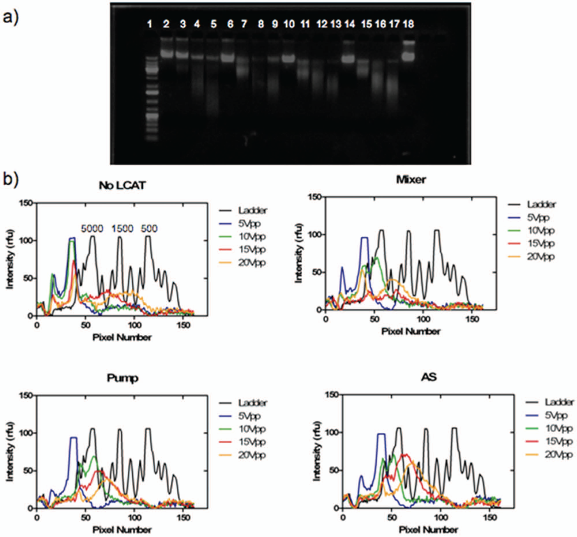
To quantify the effect of LCATs in their ability to fragment DNA, three parameters were tested: the configuration of LCATs, voltage, and time. The configuration was tested to see if the configuration of the LCAT and the microstreaming patterns could be manipulated to produce an optimal velocity gradient. The effect of voltage was then investigated to see if increasing the voltage would decrease the fragment size as well as to see the stability of the LCATs. Lastly, fragmentation time was varied to determine the time necessary for any fragmentation of DNA to occur. The frequency was maintained at the resonant frequency of the piezoelectric transducer to ensure that microstreaming occurred. Outside of the resonant frequency of the piezoelectric transducer, minimal microstreaming was observed (data not shown).
Effect of LCAT Configuration
Three LCAT configurations were tested for their efficiency in fragmenting DNA: a pump configuration, a mixer configuration, and antisymmetric (AS) configuration (
Figs. 1
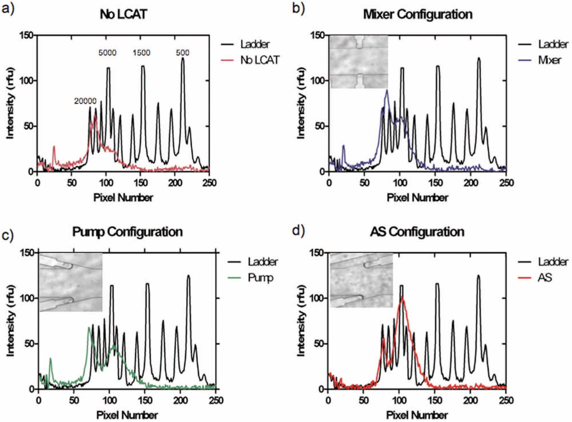
Effect of lateral cavity acoustic transducer (LCAT) configuration. DNA fragmentation for different LCAT configuration. (
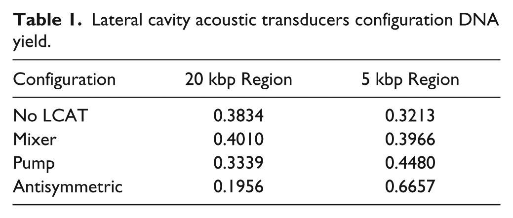
Of the three configurations, the AS configuration created the most uniform fragmentation as well as the smallest DNA fragmentation, keeping time and voltage constant ( Fig. 3d ). The voltage was kept at 10 Vpp, and the fragmentation time was 5 min. The channel with no LCAT saw some fragmentation due to cavitation occurring and the subsequent microstreaming from the cavitation. For the no-LCAT channel, the broad range of resulting DNA lengths indicates that the non–uniform-sized cavitation bubbles were produced, and the subsequent microstreaming of these bubbles was not in a controlled fashion like those achieved by devices containing LCATs ( Fig. 3a ). All three configurations as compared with simply a microfluidic channel achieved a larger percentage of fragmented DNA as well as had a narrower band of DNA sizes ( Fig. 3 ). The peaks present around 5 kbp for the mixer, pump, and AS are 50 rfu, 50 rfu, and 100 rfu, respectively, whereas for the no-LCAT configuration, there is no discernible peak and the intensity is 20 rfu. Table 1 shows the percentage of DNA present at the two peaks of 20 kbp and 5 kbp. The presence of LCATs in the channel caused 40% of the DNA present to be fragmented around the 5 kbp region, whereas without the LCATs, only 30% of DNA was fragmented. The AS configuration had the largest percentage of DNA fragmented at 5 kbp at 66% of the DNA at that size range. For the 20 kbp region, the channel with no LCATs and the mixer saw the percentage of DNA in this region to be 38% and 40%, respectively.
Lateral cavity acoustic transducers configuration DNA yield.
The size of fragmented DNA differed between the three configurations. The mixer had the biggest size at 15 kbp, with a second smaller peak at 5 kbp, whereas the AS configuration had the majority of the fragments at 5 kbp. The difference can be attributed to the streaming caused by the orientation of the LCATs. The mixer with the LCAT facing directly into the channel causes the microstreaming to be directly against each other, whereas the AS configuration allows the microstreaming to go past one another, causing a velocity gradient that is bigger than that of the mixer and pump configuration. The mixer configuration with the LCATs directly in front of each other, causes the microstreaming to interfere and not couple to create a velocity gradient that is comparable to that of the pump and AS configuration. The pump configuration allows the steaming to combine to create the flow seen at an orifice to produce a velocity gradient that allows for fragmentation. The orientation of the LCATs can be changed to control the size of the fragment obtained as well as the spread of the DNA obtained.
Effect of Voltage
Voltages of 5 Vpp, 10 Vpp, 15 Vpp, and 20 Vpp were tested for 5 min ( Fig. 4 ). The increase in voltage corresponded to an amplitude increase in the streaming, which resulted in smaller fragments. All three different configurations as well as the no-LCAT configuration were tested. Every configuration showed a shift in the main peak as the voltage was increased. The no-LCAT channel showed a wide range of DNA fragments due to the nonuniform creation of cavitation bubbles and the resultant microstreaming. Also at 10 Vpp, the no-LCAT configuration had minimal fragmentation below 20 kbp as opposed to the other three configurations. At 10 Vpp, the LCATs are able to produce the necessary velocity gradient to fragment DNA. At 15 Vpp and 20 Vpp, there is a small wide peak at about 2 kbp and 1 kbp, respectively, for the no-LCAT configuration. For the mixer, pump, and AS configuration, as the voltage increases, there is a more pronounced peak compared with a device not containing any LCATs. The pump has a peak at 4 kbp, 3 kbp, and 2 kbp for 10 Vpp, 15 Vpp, and 20 Vpp, respectively. For the AS configuration, those peaks are at 5 kbp, 4 kbp, and 2 kbp for 10 Vpp, 15 Vpp, and 20 Vpp. Although for the AS configuration, the fragment size is a bit bigger than the pump configuration, the amount of DNA present in those size ranges is greater compared with the pump configuration, indicating less variation in the length of fragmented DNA obtained when using the AS configuration.
Effect of voltage. DNA fragmentation results for 5 Vpp, 10 Vpp, 15 Vpp, and 20 Vpp for a channel with no lateral cavity acoustic transducer (LCAT) and the three configurations. (
As the voltage increased, every configuration showed a broadening of the DNA band due to cavitation at higher voltages within the channel, creating bubbles of various sizes, which in turn caused DNA to fragment into a wide range of sizes. At 5 Vpp, however, none of the configurations showed any shearing below fragment sizes of 20 kbp. Therefore, there is a minimal power requirement to induce the microstreaming and the velocity gradient needed to fragment DNA. However, because of the lack of equipment to size DNA above 20 kbp, fragmentation could be occurring even at 5 Vpp.
Effect of Time
The LCATs were tested at various times of 1 min and 10 min ( Fig. 5 ) as well as at 5 min ( Fig. 3 ) while keeping voltage and frequency constant. At 1 min, the no-LCAT, mixer, and pump configuration still showed considerable amount of DNA above 20 kbp, whereas the AS configuration showed fragmentation below 20 kbp with a peak at 5 kbp. The configuration of the LCATs can have an effect on the time necessary for DNA to fragment. With an optimal configuration that maximizes the velocity gradient, the time necessary to achieve the desired fragment size can be shortened. At 5 min and onward, all configurations show fragmentation. After a certain amount of time, the amount of fragmentation does not change, as can be shown in the 10 min fragmentation results. All different configuration show a peak around 5 kbp, with the AS configuration showing a larger peak compared with the other configurations.
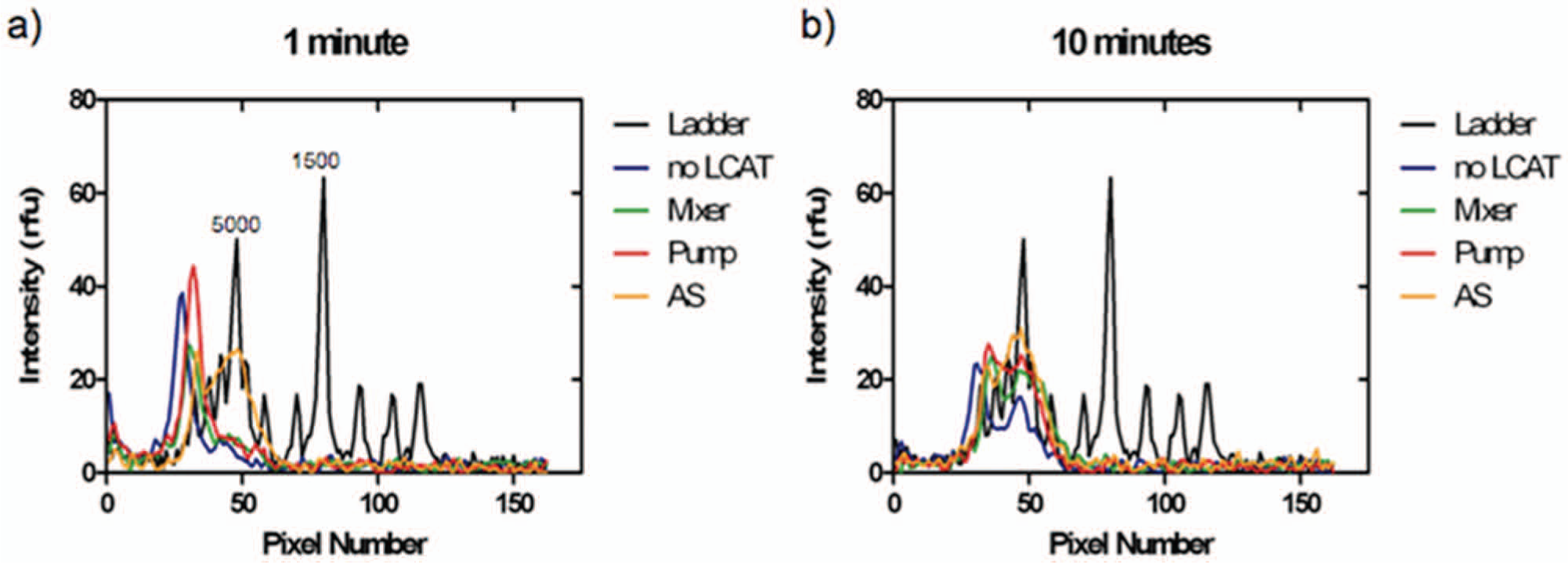
Effect of time. (
Conclusions
We present a novel method to fragment DNA using cavitation microstreaming, which requires only the solution volume that needs to be fragmented (less than 10 µL). The platform is easy to integrate with other components because only a piezoelectric transducer is needed. Furthermore, no down processing of the solution is needed after fragmentation. Depending on the configuration of the LCAT, the fragment length and the yield obtained can be controlled. The voltage as well as time can be increased to obtain smaller fragment sizes. The AS configuration, when considering voltage, time, fragmentation size, and size variation, provides the best results compared with the no-LCAT, mixer, and pump configuration. Compared with simply a microfluidic channel with ultrasound applied, LCATs introduce controlled microstreaming into the channel, which allows for a sharper peak of DNA fragments. Further work can be done to see how different LCAT sizes can better control for the fragment size and yield of DNA.
Footnotes
Acknowledgements
The authors would like to thank Dr. Michael Hayes and Karolyn Giang in Professor Mulligan’s lab for the use of their gel setup and advice. The authors would also like to thank Professor Steve George’s lab for use of their gel setup and imager. Finally, the authors would like to thank Maulik Patel (Momo) for helpful discussions.
Declaration of Conflicting Interests
The authors declared no potential conflicts of interest with respect to the research, authorship, and/or publication of this article.
Funding
The authors disclosed receipt of the following financial support for the research, authorship, and/or publication of this article: This work was supported in part by the Defense Advanced Research Projects Agency (DARPA) N/MEMS S&T Fundamentals Program under grant N66001-1-4003 issued by the Space and Naval Warfare Systems Center Pacific (SPAWAR) to the Micro/nano Fluidics Fundamentals Focus (MF3) Center. This work was supported in part by DOD Defense Threat Reduction Agency (DTRA) subcontract from General Electric Co. (HDTRA1-10-C0033).
References
Supplementary Material
Please find the following supplemental material available below.
For Open Access articles published under a Creative Commons License, all supplemental material carries the same license as the article it is associated with.
For non-Open Access articles published, all supplemental material carries a non-exclusive license, and permission requests for re-use of supplemental material or any part of supplemental material shall be sent directly to the copyright owner as specified in the copyright notice associated with the article.