
Abstract
We report an on-chip acoustofluidic method for sequential trapping and transporting of microparticles via acoustically oscillating bubbles. The size and location of bubbles were precisely controlled by lithography. When the acoustic waves were turned off, particles followed the streamlines dictated by laminar flow. When the acoustic waves were turned on, particles were attracted to and trapped in a vortex near the surface of bubble. Therefore, particles could move across the microfluidic channel with programmed trajectories. Additionally, a theoretical model based on acoustic radiation force and drag force due to acoustic microstreaming was established to help design this particle-trapping and -transporting system.
In the past two decades, the field of microfluidics has shown great promise and affected many areas such as chemical synthesis and medical diagnostics.1–4 In many microfluidic-based studies and applications, such as cell separation and sorting,5–8 it is essential to have techniques that can actively control and manipulate the trajectories of microparticles, such as cells. 9 To control the trajectories of microparticles, an external force field needs to be exerted on particles within a microfluidic device so that selected particles can overcome the effects of laminar flow and change their trajectories. 10 Based on this principle, several methods have been successfully developed to manipulate particle trajectories. Hydrodynamic effects11–16 can direct particles by manipulating the laminar streamlines in certain-shaped microfluidic channels. Charged or magnetic particles can be controlled by external electric17–19 or magnetic fields.20,21 Particles can also be manipulated by optical forces using optical tweezers 22 or optoelectronic tweezers. 23
Recently, acoustic methods have attracted significant attention as an alternative way to manipulate particles. 24 Compared with other particle manipulation approaches, acoustic manipulation offers many advantages: it is compact, noninvasive, contact free, and versatile. However, the wavelengths for most commonly used acoustic transducers are much longer than the micrometer scale, which seems unfavorable for on-chip particle manipulation. One approach to overcome this barrier is to use high-frequency (~10 MHz) acoustic transducers to achieve acoustic waves with short wavelengths (e.g., 100 µm).25–32 An alternative approach for acoustic manipulation is to use acoustically oscillating bubble-based systems,33–48 in which the experimental setups could be significantly simplified while keeping all advantages of the previously recognized acoustic manipulation methods. In such systems, low-frequency (kHz range) acoustic waves oscillate the air-liquid interface of a bubble, and this oscillation manipulates the particles through the relatively strong effects of acoustic streaming and radiation force. Even at low frequencies (kHz range), this oscillatory response is confined to a region comparable with the radius of the bubble (~100 µm), which makes it possible to achieve on-chip control of the particle trajectory. A few researchers reported the trapping and manipulation of particles using acoustically oscillating bubbles33,34,37,38,40,41,44–46; however, the particle-trapping effect occurs only in short range because of the limited working range of a single oscillating bubble. In addition, in these approaches, the position and size of the bubbles were difficult to control. Therefore, to develop a practical, on-chip, particle manipulation method using acoustically oscillating bubbles, one must use multiple bubbles with precise control on the size and location.
In this article, we report a simple, single-layer, microfluidic device that can control the trajectory of particles by acoustic oscillation of multiple bubbles trapped in horseshoe-shaped structures. Our device can conveniently and precisely control the position and size of bubbles. The bubble size determines the oscillation behavior at prescribed frequencies; the location of the bubble determines the direction to which the particles will move. Thus, we can optimize the resonance frequency of the bubbles and precisely position them to maximize particle-transporting efficiency. Moreover, by applying multiple bubbles, this device is capable of controlling the trajectories of particles in a large range, mitigating the disadvantage of using only a single bubble, whose ability to affect particle trajectory is limited to a relatively small region. The use of multiple bubbles also allows the sequential manipulation of particles, thus compounding influence on the desired trajectory and creating an acoustofluidic relay.
Materials and Methods
Device Design and Experimental Setup
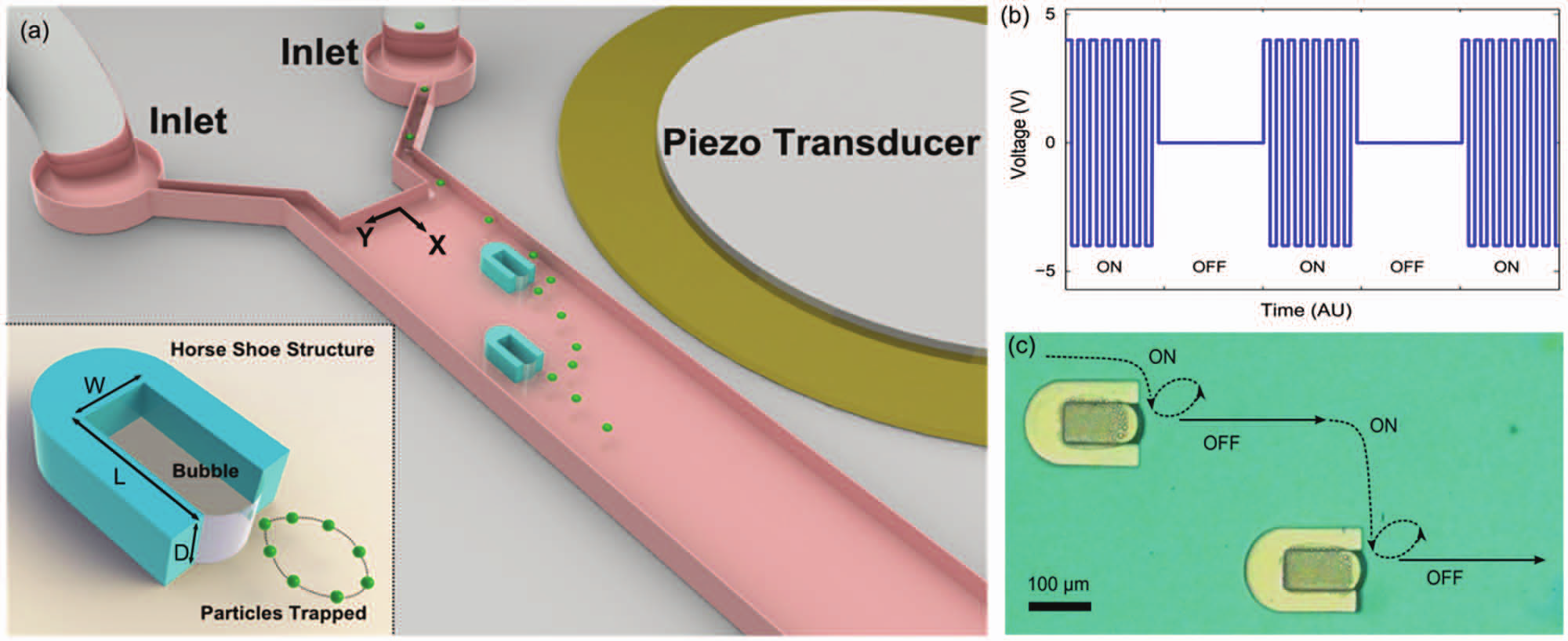
The polydimethylsiloxane (PDMS)–based microchannel was fabricated using a standard soft lithography technique49,50 and was bonded to a glass slide ( Fig. 1a ). The channel width, depth, and length were 570 µm, 90 µm, and 1.5 cm, respectively. The device featured two horseshoe structures having widths (w), lengths (l), and depths (d) of 60, 120, and 90 µm, respectively (inset of Fig. 1a ). The distance between the two bubbles in the x-direction was 350 µm, and the distance in the y-direction was 90 µm. When the liquid filled the channel, a bubble formed in each horseshoe structure due to surface tension. A piezoelectric transducer (model No. 273-073; Radioshack Corp., Fort Worth, TX) was bonded adjacent to the PDMS microfluidic device on the same glass substrate using epoxy ( Fig. 1a ). The piezoelectric transducer was driven by a function generator (Hewlett Packard 8116A) in a burst function mode ( Fig. 1b ). In this mode, the function generator generated a square wave during the on time (tON), with a frequency matching the natural resonant frequency of the bubbles, and no voltage was applied during the off time (tOFF). The peak-to-peak voltage (Vpp) was set to 8 V, which generated suitable bubble oscillation amplitude to attract particles while keeping the bubble stable. The driving frequency was set at 32 kHz, which was based on the calculated resonant frequency of bubbles.
(
To demonstrate particle trapping and transportation, a solution of polystyrene microparticles (diameter 10 µm) in deionized (DI) water was injected through one channel inlet; the concentration of the particles was about 105 per milliliter. Pure DI water was supplied through the other. Without acoustic waves, the particles were confined to only one side of the channel due to laminar flow in the channel. When the piezoelectric transducer was turned on, nearby particles were attracted to the bubble and trapped in a vortex ( Fig. 1c , dashed lines). Turning off the transducer at this time released the particles, allowing them to follow the laminar flow in the channel to the proximity of the second bubble ( Fig. 1c , solid lines). When the transducer was again activated for a time tON, the particles were attracted to the second bubble, after which the transducer was again deactivated and the particles were released. In this manner, an acousofluidic relay was created by alternating between the on and off states of the piezoelectric transducer. This allowed manual control of movement time across the laminar streamlines and thus manipulation of particle movement across the channel.
The particles’ moving trajectories were recorded by a CCD camera (Casio Exilim Pro EX-F1) at 600 frames per second. The resulting videos were processed by Image J software to track the particle location at every frame and analyze the particle velocity.
Results
Characterization of the Resonant Frequency of Bubbles
When the piezoelectric transducer was turned on, the bubble started to oscillate, which generated fluctuations in the velocity and pressure of the liquid surrounding the bubbles and perturbed the laminar flow in the channel. 51 The bubbles oscillated most effectively at their resonant frequency, which is roughly estimated by the small-amplitude behavior of the Rayleigh-Plesset equation 52 :
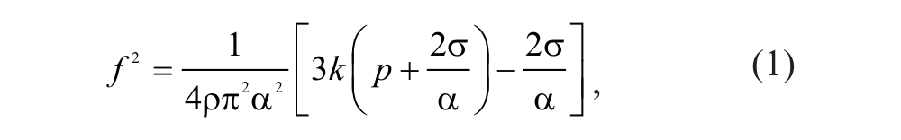
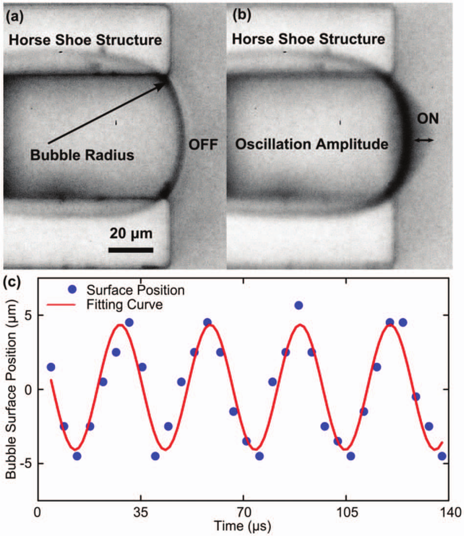
where ρ is the density of the liquid (1000 kg/m3), σ is the surface tension of solution (0.0728 N/m), κ is the polytropic exponent for a bubble containing air (1.4), p is the fluidic pressure (101,325 N/m2), and α is the radius of the bubble in meters. The radius of each bubble, determined from the image in Figure 2a , was approximately 80 μm, and its natural resonance frequency was calculated to be 41 kHz. Experimentally, the maximum bubble oscillation was observed to be in the range of 30 to 35 kHz. The discrepancy between the experimental and calculated resonant frequencies can be attributed to the nonspherical shape of the air bubbles trapped within the horseshoe structures. Figure 2b shows bubble oscillation in the presence of acoustic waves. The detailed bubble oscillation behavior was characterized by a fast camera (Photron Fastcam SA4) at 225,000 fps while stimulating the bubble with 32 kHz acoustic waves. The middle point of the bubble surface was tracked ( Fig. 2c ). The experimental results verified that the bubble oscillated at about 32 kHz, almost the same as the frequency of the stimulating acoustic waves. The amplitude of the bubble oscillation was observed to be about 4.5 µm. The average oscillating velocity (u0) of the bubble surface could be estimated by changes in bubble surface position between each frame, as 0.56 m/s.
(
Force Analysis for Particle Transport
Once microparticles were injected into the acoustic-induced fluidic field, the motion of particles was dictated by two forces: the drag force (Fd) from acoustic streaming and the acoustic radiation force (Fr). At a low Reynolds number, the drag force Fd on a spherical particle was

where Rs is the radius of the particle, η is the medium viscosity, and ν is the relative velocity between the particle and the fluid. However, it is very difficult to determine ν at each x and y position in a flow field. Thus, we used maximum velocity (UL) to estimate the upper limit of the velocity of a particle in the vortex. The streaming patterns generated by the oscillating bubbles were studied before 51 , and the maximum velocity of the liquid within the boundary layer of streaming is 53

where ω = 2πƒ; Rp is the radius (80 µm) of an ideal spherical acoustic source, which is approximated as the surface curvature of the bubble in Figure 2b ; u0 is the velocity amplitude of the oscillating interface (calculated as 0.56 m/s by the fast camera; Fig. 2c ), and r is the distance to the bubble surface. When the particle is introduced into the flow field, the particle Reynolds number is still very small; thus, the maximum drag force due to acoustic streaming could be estimated by

The radiation force (Fr), derived by the time-averaged, second-order momentum terms in the Navier-Stokes equation, 54 also affects the particles and is described by

where ds is the density of the particle, dm is the density of the medium, and B = 3(ds − dm)/(2ds + dm) is the constant that determines the direction of the radiation force on the particle (B > 0, attractive force; B < 0, repulsive force). As a design parameter for our transportation system, the ratio of streaming-induced drag force and radiation force was attained by combining eqs 3, 4, and 5:

Equation 6 shows that with higher oscillating frequency or relatively large particle size, Fr plays a more important role in the motion of the particle than Fd, causing the particles to attract to the surface of the bubble. Otherwise, Fd would determine the trajectories of particles, and the trajectories would be similar to the streaming pattern. Because eq 6 is derived from FdMAX, rather than Fd, it provides only a qualitative analysis. Nevertheless, it is still valuable for the design of our experimental system. If the ratio in eq 6 was larger than 1, or even close to 1, Fr would dominate Fd (because Fd is always less than FdMAX) and the particles would be trapped at the surface of the bubble. On the contrary, if the ratio is much less than 1 (e.g., 0.01), the drag force would dominate the system and the particles would easily escape the vortex by following streamlines. Our design avoided these two extreme situations because the bubble radius was 80 µm, which fixed the bubble resonant frequency at 30 to 35 kHz, and the particle size was 10 µm. These parameters resulted in a balanced ratio of Fr/FdMAX at about 0.2 to 0.3. Thus, the frequency that induced a maximum oscillation of the bubble coincided with the condition in which 10 µm particles would neither easily escape the vortex nor attach to the bubble surface. At this frequency, the particles would be trapped in the vortex near the surface of the oscillating bubble.
Particle Transport between Bubbles
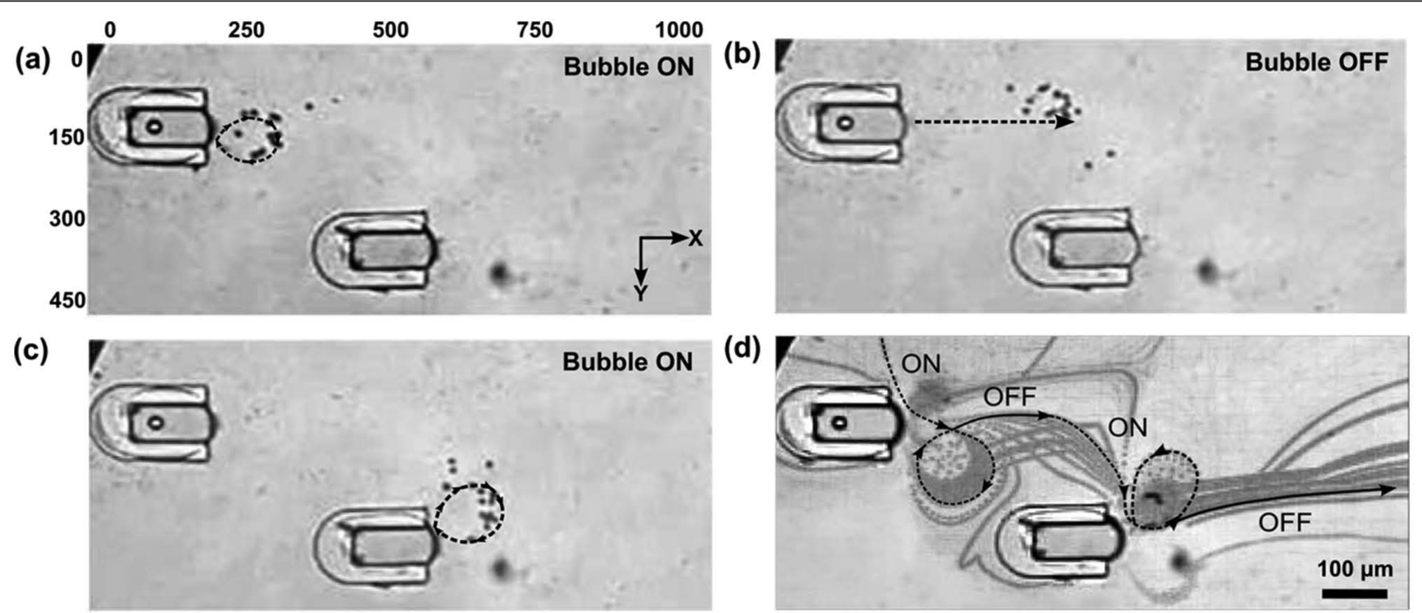
The experimental results (
Fig. 3
) confirm the design principle derived from eq 6.
Figure 3a
(
The quantitative trajectory analysis of a single particle (
Fig. 4a,b
) from our experimental results revealed additional information about the particle-trapping and -transportation process. In
Figure 4a
, before the piezoelectric transducer turned on, the particle moved almost linearly (diverging slightly due to the presence of the horseshoe structures) with constant velocity due to laminar flow in the channel. After the piezoelectric transducer was turned on (point I in
Fig. 4a
), the particle attracted to the bubble, and its velocity increased. The moving direction of the particle was not directly toward the bubble because of the injecting flow in the x-direction. The speed of the single particle during the trapping process (
Fig. 4c
) was calculated by dividing the distance between each subsequent position of the particle in the video by the time interval between each frame. When the particle was far from the bubble (point I in
Fig. 4a
), the speed was almost constant. At that distance, both the radiation force and the drag force (either from the mainstreaming or from the acoustic streaming) were too weak to significantly influence the particle motion. As the particle approached the bubble, the speed increased dramatically (point II in
Fig. 4a
). This increase in speed was caused by two factors: the fluid velocity increased due to acoustic streaming within the vortex near the bubble surface, and the radiation force increased as the particle approached the bubble. Similar analysis was applied for the rotation process in
Figure 4b
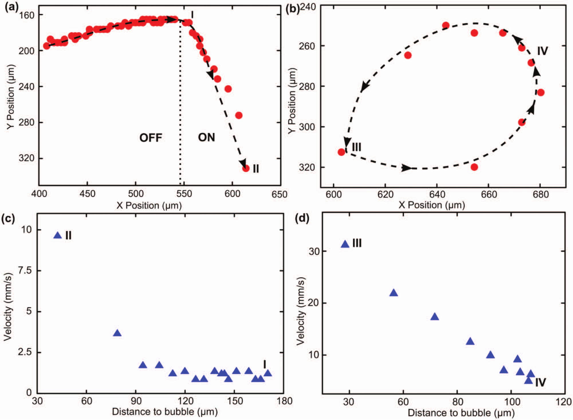
(
Summary
In summary, we report a bubble-based, acoustofluidic method for trapping and transporting particles in a microfluidic channel. Our approach can precisely position bubbles with prescribed sizes through the use of strategically placed horseshoe-shaped microstructures and thus accurately control the particle-transportation process. By cycling the acoustic waves on and off, the particles were trapped, rotated, and transported among multiple bubbles, causing them to move transversely across the channel via an acoustofluidic relay. We also developed a simple model that balances the effects of drag force and radiation force and provides guiding principles for designing this acoustofluidic device. The technique presented here is useful for the trapping and transport of particles or cells in microfluidic devices and facilitates the further integration of bubble-based, lab-on-a-chip systems.
Footnotes
Acknowledgements
We thank Jason Scott and Nicholas Labarbera for helpful discussion.
Declaration of Conflicting Interests
The authors declared no potential conflicts of interest with respect to the research, authorship, and/or publication of this article.
Funding
The authors disclosed receipt of the following financial support for the research, authorship, and/or publication of this article: This research was supported by National Institutes of Health (Director’s New Innovator Award, 1DP2OD007209-01), National Science Foundation, and the Penn State Center for Nanoscale Science (MRSEC). Components of this work were conducted at the Penn State node of the NSF-funded National Nanotechnology Infrastructure Network.