
Abstract
A microfluidic component library for building systems driving parallel or serial microfluidic-based assays is presented. The components are a miniaturized eight-channel peristaltic pump, an eight-channel valve, sample-to-waste liquid management, and interconnections. The library of components was tested by constructing various systems supporting perfusion cell culture, automated DNA hybridizations, and in situ hybridizations. The results showed that the MainSTREAM components provided (1) a rapid, robust, and simple method to establish numerous fluidic inputs and outputs to various types of reaction chips; (2) highly parallel pumping and routing/valving capability; (3) methods to interface pumps and chip-to-liquid management systems; (4) means to construct a portable system; (5) reconfigurability/flexibility in system design; (6) means to interface to microscopes; and (7) compatibility with tested biological methods. It was found that LEGO Mindstorms motors, controllers, and software were robust, inexpensive, and an accessible choice as compared with corresponding custom-made actuators. MainSTREAM systems could operate continuously for weeks without leaks, contamination, or system failures. In conclusion, the MainSTREAM components described here meet many of the demands on components for constructing and using microfluidics systems.
Introduction
Microfluidics offers fundamentally new capabilities in the control of concentrations of molecules in space and time compared with traditional techniques, enabling new possibilities and systems in a variety of fields such as cell biology, structural biochemistry, and analytical chemistry. 1 However, practical concerns, including reliability, accessibility, affordability, portability, ease of use, assembly, integration, and control of microfluidic devices, hinder their usability and, ultimately, their implementation into a commercial setting.1–6 The majority of the practical concerns raised above can be resolved using a platform-based approach. Platforms provide components that enable a set of fluidic unit operations to be easily combined and should provide means for simplified, rapid, and cost-efficient construction of application-specific systems designed for individual (bio)chemical processes. 7
In this article, we present the design and fabrication of platform components and demonstrate how these can be connected together into assorted microfluidic systems for a variety of applications. We refer to this platform approach and component family as MainSTREAM. The MainSTREAM component approach enables the creation of a multitude of microfluidic lab-on-a-chip (LOC) systems that address the majority of the practical concerns described above. The system incorporates all components required for the flow of sample to waste through the LOC system (i.e., pumps, valves, microfluidic reaction chips, reagent vials, waste containers, component interconnections, and computer controlled actuation).
Modular microfluidic systems of either academic or commercial origin exist (www.epigem.co.uk; www.labsmith.com; www.thinxxs.com)8–13 and are largely influenced by both LEGO and electronic breadboards. In general, these systems aim to provide methods to rapidly assemble sealed microfluidic networks by simplifying the interconnection of microfluidic chips. These modular systems present easily reconfigurable elements that can be assembled quickly, allowing flexibility in design and construction of fluidic networks.7,12,13 However, they fail to address and resolve fluidic actuation, routing, control, and sample-to-waste liquid management (www.epigem.co.uk; www.labsmith.com; www.thinxxs.com).8–13 The resulting systems consist of chips that need to be connected to actuators (e.g., large syringe or peristaltic pumps), which might be difficult to place near or within detection instruments, incubators, and so on. Moreover, the extended tubing required for interfacing the microfluidic chips to this macro world results in large dead volumes and poor liquid control due to pressure buildups, interferes with detection, and limits system portability. Put differently, system-level problems will negatively affect chip functionality and general usability.
Improved system-level performance and usability could increase by downscaling and integrating components (i.e., pumps, valves and sample-to-waste liquid management) into a single device. Some existing examples are the integration of fluidic actuation and routing functions using multilayer elastomeric approaches, including microfluidic large-scale integration (MLSI)14–16 and Braille display–activated microfluidic chips,17–19 both offering large multiplexing capabilities. However, the actuators, external pressure sources, solenoids, controllers, reagent, and waste vials required to drive MLSI systems limit the portability of the approach. 7 The Braille17–19 may overcome portability issues, but its implementation is slow due to the complexity of the equipment and the unconventional nature of the platform. 6 In addition, sample-to-waste liquid management is not easily integrated with the MLSI and Braille display approaches.
Connecting numerous sample holders (from µL to mL in volume) directly to chips without the need for tubing is not a trivial issue but, if successfully achieved, simplifies and reduces the footprint of the microfluidic system and resolves the µm to cm scale disparity between features of microfluidic chips, pumps, valves, and sample holders. Point-of-care (POC) platforms and systems address many of these issues, 7 leading to portable and user-friendly systems based on a customized control box, running fluidic cartridges. The cartridges often contain sample ports, as well as all reagents and components required for detection and quantification of analytes, and the control box usually contains the actuators (required to move and control liquids within the cartridge), the detection unit, and a user interface. However, POC systems are mainly designed for repetitive and standardized assays and may not suit the varying needs and day-to-day changes potentially required by researchers.
With the above in mind, we set out to design components that can be used to build systems that have the flexibility and scalability of established microfluidics platforms (www.epigem.co.uk; www.labsmith.com; www.thinxxs.com)8–19 but also offer the portability and reliability of point-of-care platforms. 7 The resulting component family forms the basis of the microfluidic platform we designate as MainSTREAM.
The MainSTREAM component platform evolved from two previously described achievements: independently addressing interconnections20,21 and micropumps. 21 These components have been used to construct a parallel cell-culturing device. 22 Here we broaden the MainSTREAM component list, including valves and reagent and the waste management system. Furthermore, here the custom-made computer controllers and the visual basic programming interface 22 are replaced with off-the-shelf, readily available, and affordable LEGO Mindstorms (LEGO, Billund, Denmark) motors and controllers and a LabView-based programming interface (National Instruments, Austin, TX). Taken together, these new components and methods to actuate pumps and valves allow for the construction of compact, portable, cost-efficient experimental units without sacrificing flexibility and scaling of microfluidic system construction. The general applicability of MainSTREAM components was tested by building several microfluidics systems driving exchangeable microfluidic chips for genotyping, cell culture, and in situ hybridization (ISH) applications. Finally, we present data and discuss the reliability and usability of systems built with the MainSTREAM components.
Materials and Methods
General Fabrication
Unless otherwise stated, all MainSTREAM components, and elements thereof, were based on computer numeric-controlled (CNC) micromilled components.20,21 Multilayer poly (methyl methactrylate) (PMMA) chips were bonded via a UV-assisted bonding process. 23 Bonding faces of the PMMA chips were exposed to UV (DYMAX EC 5000 with p/n 36970 bulb; DYMAX, Torrington, CT) for 1 min and subsequently bonded between glass plates in a bonding press (P/O/Weber, Remshalden, Germany) at 85 °C for 10 min at an initial applied force of approximately 8 kN for chips measuring 26 × 76 mm and 13.50 kN for chips measuring 52 mm × 76 mm. PDMS (Sylgard 184; Dow Corning, Midland, MI) used for elastomeric components was mixed in a 10:1 mass ratio of elastomer to curing agent and placed under vacuum to remove air bubbles. PDMS components were cured overnight at 65 °C.
Microfluidic Ribbons (µFRs)
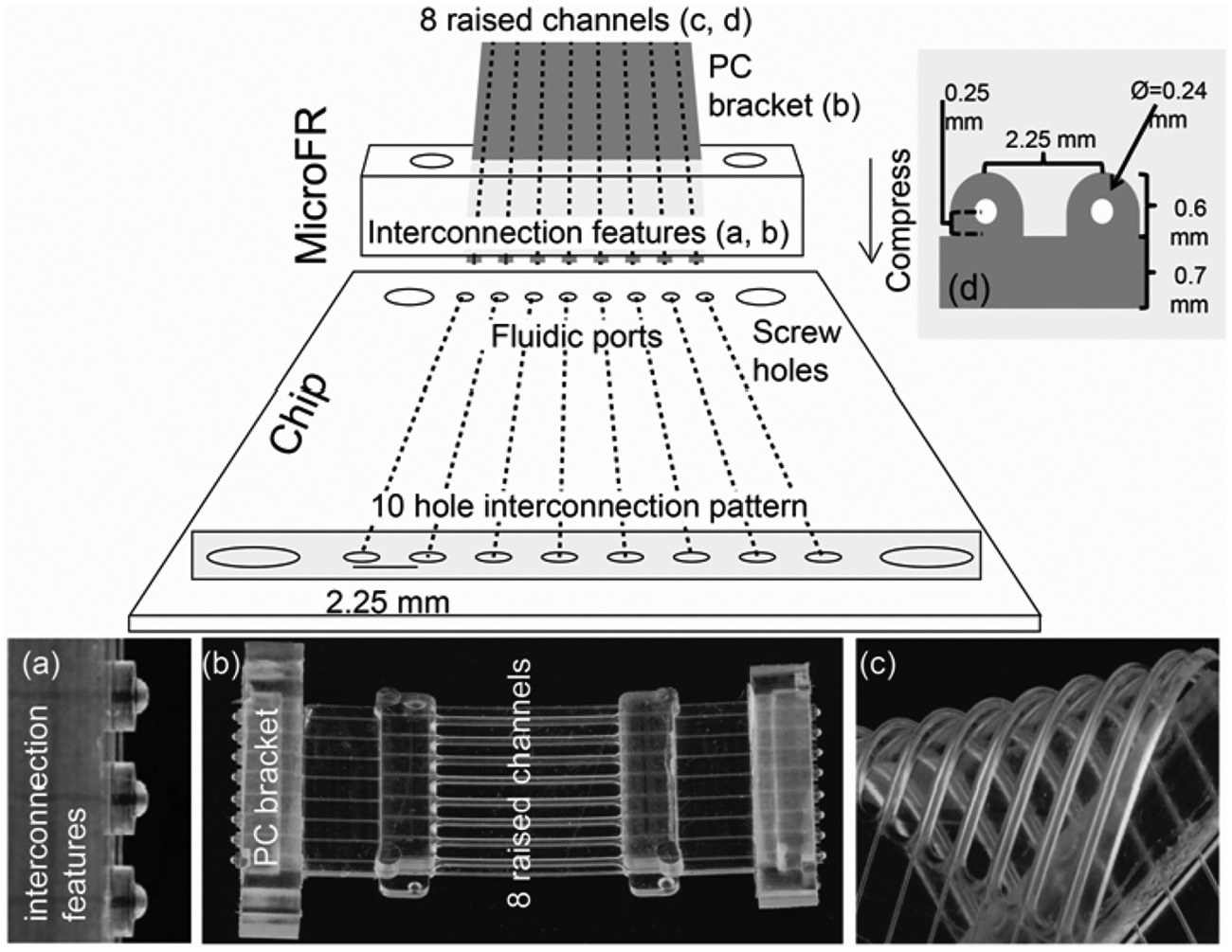
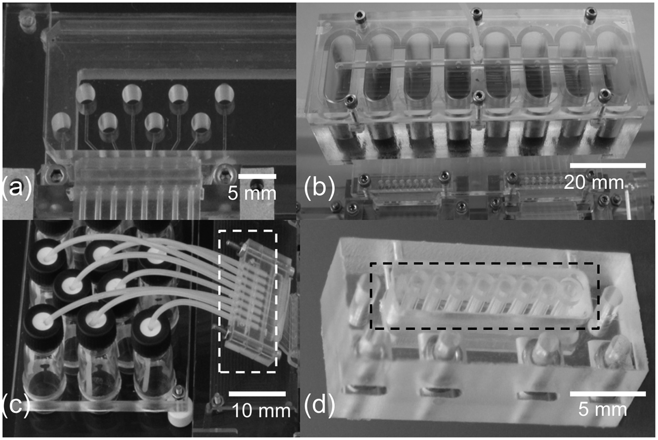
The MainSTREAM type I µFRs ( Fig. 1b ) are designed for use in the micropump ( Fig. 2 ) and the camshaft valve ( Fig. 3 ) and connect microfluidic elements found on both sides of the micropump and valve. Principles for connecting a µFR to a chip are shown in Figure 1 . Type I µFRs are monolithically cast from PDMS by a method previously described20,21 and contain eight integrated circular 240-µm diameter channels spaced 2.25 mm center to center (1536-well plate standard). The raised tubing-like features ( Fig. 1c , d ) of the type I µFRs are closed during micropump and valve operations. Type II µFRs (not shown) are shorter versions of the type I µFR and are used as chip-to-chip interconnections. All µFR channels end with ball joint features ( Fig. 1a ), which provide self-aligning, minimal dead volume interconnections. 20 Polycarbonate (PC) brackets ( Fig. 1 ), either square or round in shape ( Fig. 1b ), are placed into the µFR molds prior to PDMS casting and during curing integrated into the µFR. Overall dimensions, including the PC brackets, of type I and II µFRs are 48 mm (l) × 30 mm (w) × 5 mm (h) and 20 mm (l) × 30 mm (w) × 5 mm (h), respectively. The MainSTREAM microfluidic reaction chips (see Fig. 1 for principle) and vial management systems (see Fig. 4 ) must contain a 10-hole pattern matching that of the µFRs. The inner eight of these holes are inlet or outlet holes 0.8 mm in diameter and a center-to-center distance of 2.25 mm. The two outer holes are 2 mm in diameter and allow µFRs to be attached to microfluidic chips via 2-mm screws.
Description of µFR and standardized interface to chip. Microfluidics ribbon (
Micropump. (
Camshaft valve. (
Liquid management. (
The Micropump
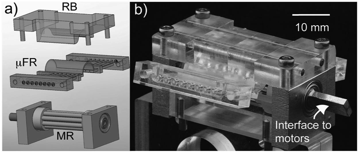
The MainSTREAM micropump ( Fig. 2 ) is a further miniaturized and improved version of a multichannel, mechanically actuated peristaltic pump previously described. 21 The three main parts of the micropump are (1) a multiroller (MR), (2) a rotor bed (RB), and (3) a type I µFR ( Fig. 2a ). The MR is made from aluminum blocks, which house 4-mm inner-diameter (ID) ball bearings (VXB Bearings, Anaheim, CA). Nylon disks mounted on a central brass shaft align eight free-rolling 2-mm stainless steel pins. The RB is made from PC. When attached to the micropump, the RB’s shape results in occlusion of the type I µFR tubing features between the RB and the MR’s rolling pins. This enables peristaltic pumping. The footprint of an assembled micropump with type I µFR attached to microfluidic chips excluding motors is 30 mm (w) × 40 mm (l) × 20 mm (h). The brass shaft ( Fig. 2b ) was used to interface to motors or hand cranks.
The Valve
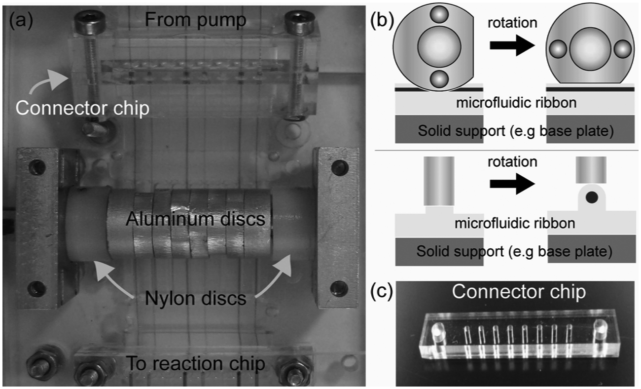
The camshaft ( Fig. 3a ) is fabricated from the same parts as the micropump’s MR except that the stainless steel pins are replaced with individual cams that are stacked and aligned along a central 4-mm brass shaft and 2-mm alignment pins running between the nylon disks. Cams ( Fig. 3a , b ) are made from aluminum and have a radius of 4.66 mm, a flat cut face, a 4-mm diameter central hole, and 2-mm through holes. The 4-mm diameter central hole allows the cams to be placed on the camshaft. The 2-mm through holes allow flat cut faces of cams to be aligned at defined angles and positions relative to each other. To operate as a valve, the type I µFR is placed on a flat solid support under the camshaft. The height of the camshaft is set so that when the flat cut face of a cam is parallel to a µFR channel, the channel remains open ( Fig. 3b ). Rotation of the camshaft to a position that places any circular portion of the cam above a channel results in contact between the cam and the µFR channels. This depresses the tubing wall against the solid support and closes the channel. The eight aluminum cams are machined to thicknesses so that each cam is centered directly above each of the µFR’s eight channels ( Fig. 3a ). The cams were arranged so that each 45° rotation of the camshaft allows flow through only one of the µFR’s eight channels at a time. The 45° steps continue in the same direction sequentially along the camshaft. If the starting camshaft position is assigned as 0° with channel 1 of the µFR open, sequential 45° camshaft rotation steps in the same direction as the 45° steps of the cams’ flat faces will permit flow through only channel 1, then only channel 2, then only channel 3, and so on, up to channel 8. Prior to operation, the valve’s camshaft was manually aligned to a predetermined position.
Sample-to-Waste Liquid Management
MainSTREAM well arrays (WAs) (
Fig. 4a
,
b
) are used to store reagents, samples, and waste material. The WA chips also contain the 10-hole pattern to interface to µFR. For applications requiring small volumes, multilayer PMMA or PC-based WAs were used (
Fig. 4a
). For applications requiring larger volumes, WAs were made from layers of PMMA sealed with PDMS gaskets (
Fig. 4b
). Glass vials can also be used for liquid management. Glass vials are interfaced to chips and pumps using a tube connector (TC;
Fig. 4c
and
For cell culture applications, a cell-loading chip (CLC) ( Fig. 4d ) is used. The CLC contains a PDMS portion integrated within a PC frame. The PC frame contains inset nuts that facilitate attachment to other components. The PDMS portion is monolithically cast as previously described. 24 In this case, 1.5-mm diameter pins are used to create eight wells with a volume of approximately 15 µL each. The wells are bookended with O-ring sealing features 24 on the bottom and top side. A lidding piece of PC is attached and sealed against the top of the CLC with screws. This lidding piece contains either a single or eight press-fitted PTFE tubings (hereafter referred to as tube block, TB) to collect waste liquid. To introduce cells into the microfluidic system, the top piece is detached by removing screws. Cells can then be loaded into individual wells and the top piece reattached.
System Assembly
All MainSTREAM components are typically attached to a base plate using 2-mm screws and corresponding nuts. Base plates, made from PC, contain arrays of 2-mm holes in which 2-mm screws are inserted to position micropumps and camshaft valves in place. Base plates also contain recesses matching microchip dimensions to fit the chips within the system. In some cases, 2-mm nuts were press-fitted into undersized recesses within the base plate to facilitate attachment of MainSTREAM components to each other. Brackets complementary to the shape of µFRs’ end brackets are sometimes attached to the base plate adjacent to micropumps or camshaft valves. These guide µFR end bracket placement prior to the attachment of the µFRs to other components. The base plate and the mounted components (pumps, valves, and liquid management systems) are then treated as a single unit that can be interfaced with a chip. The base plate contains guiding structures so that chips are easily connected to the base plate carrying the system-to-chip interconnection features.
Actuation and Control of Micropump and Camshaft Valve
For microfluidic networks requiring greater levels of automation or for assays of longer duration, the LEGO Mindstorms NXT2.0 robotics kit (www.LEGO.com) was used (
Genotyping in MainSTREAM
Hand crank–driven micropumps were used to genotype patient samples for mutations in the human β-globin (HBB) gene 25 via an allele-specific hybridization (ASH) assay. Microfluidically addressable microarrays were incorporated within PMMA chips using a UV-activated poly(T)-poly(C) probe tag as described. 25 A PMMA genotyping chip sized identically to a microscope slide and containing 16 microfluidic lanes was interfaced to two micropumps. Each lane of the chip measured 1.5 mm (w) × 0.25 mm (h) × 21 mm (l) and was bookended by 0.8-mm inlet and outlet holes. Each lane contained DNA arrays constructed from poly(T)-poly(C)–tagged probes. The DNA microarrays allowed ASH based genotyping of CD17, CD26, and IVS+5 mutations in the HBB gene. The probe pairs used for ASH genotyping of these three mutations are provided in the supplemental information. Target preparation from patient archive material and washing buffers for the genotyping experiments were prepared as previously described 25 and were transferred from a loading chip through the pump and into the PMMA genotyping chip by turning the hand crank. Solutions were sequentially introduced into the PMMA chip. Prior to the introduction of the subsequently required solution, the solution within the chip lanes was pumped out and absorbed dry with a paper towel. Approximately 12 µL of each solution was used at each step, and the procedure was as follows: Channels were first filled with 5 µL of 0.1× saline-sodium citrate (SSC) supplemented with 0.5% sodium dodecyl sulfate (SDS) and incubated for 10 min to solubilize probes not bound to the surface after spotting the arrays with a Nanoplotter (GeSim, Grosserkmannsdorf, Germany). The channels were then washed with additional 5 µL wash of 0.1× SSC supplemented with 0.5% SDS to remove unbound probes. A fluorescently Cy3-labeled patient material was prepared by PCR amplification and subsequent T7 in vitro transcription, and the resulting amplified RNA were diluted 1:1 in hybridization buffer (10× SSC supplemented with 1% SDS). 25 Hybridization was performed at 37 °C in a dark, humid chamber for 2 h. The hybridization solution was then removed to prepare for multisalinity gradient washing. Multisalinity gradient washing allows genotyping via parallel analysis of identical arrays treated with different stringency wash buffers.26,27 In this case, each of the four lanes used to genotype a single patient was filled with one of the following four washing buffers: 2.0× SSC, 0.55× SSC, 0.10× SSC, and 0.035× SSC, all supplemented with 0.1% SDS, corresponding to 331.0, 91.6, 17.3, and 6.6 mM Na+, respectively. The lanes were filled for 1 min at room temperature to remove excess and unbound target. Following this, the lanes were filled with the wash buffers and left for 30 min at 41 °C. Hybridization reactions were imaged using a Zeiss Axio Observer.Z1 microscope (Carl Zeiss, Jena, Germany). Identical focal and camera settings were used for all images collected. All signals were analyzed with GenePix Pro 6.1 (Molecular Devices, Sunnyvale, CA) and analyzed according to the multisalinity gradient washing method, which allowed for the use of probes with different washing buffer optima in the same microarray.26,27
In Situ Hybridization
An ISH assay was performed by attaching a device, called HistoFlex, 28 to a MainSTREAM system. In brief, HistoFlex encompasses a patterned PDMS insert, which upon sealing aligns microfluidic reaction chambers to tissue sections fixed on a microscope slide. 28 Integrated channels in the PDMS insert permit fluid delivery to and from these reaction chambers. Temperature is controlled using peltier elements. In this report, the HistoFlex fluidics was driven and controlled using MainSTREAM components (i.e., a valve component, an eight-channel micropump, and interconnection components). HistoFlex is not part of the MainSTREAM platform, and its interconnection features are not directly compatible with MainSTREAM components. HistoFlex was therefore connected to the MainSTREAM platform through a merging chip (MC) and a specially designed TC. The MC merges the output of the eight channels, first into groups of six and two channels and subsequently into a single channel, connected to the HistoFlex using the TC. Casting techniques are used to create an O-ring feature at the end of a 1.6-mm through channel found within a PDMS block housed in a polymeric bracket. The bracket was attached to the MC using 2-mm screws. Then, 0.2/1.7-mm inner/outer diameter tubing (Bola; Bolender, Grünsfeld, Germany) was press-fit into the PDMS block. The other end of the tubing was inserted into a similar cavity in the HistoFlex PDMS insert, which was connected to a reaction chamber. Waste from the reaction chamber was collected through tubing into a glass vial.
An ISH assay was performed for detection of microRNA-138 (miR-138) in formalin-fixed paraffin-embedded (FFPE) mouse brain tissue sections by adapting the protocol and solutions presented by Søe et al.28,29 Reagents were prepared in 0.2-, 1.5-, or 9-mL vials and placed in the vial rack. Vials were filled as follows: channel 1 (C1) = phosphate-buffered saline (PBS), C2 = prehybridization buffer, 28 C3 = hybridization buffer (40 nM miR-138 in 1× SSC, 4M urea, and 1× Denhardt’s), C4 = 0.1× SSC, C5 = blocking buffer, C6 = Cy3-tyramide signal amplification solution, C7 = anti-FITC antibody conjugated to a horseradish peroxidase (HRP) enzyme, and C8 = PBS. Merging all channels of the MC at a single point could result in unwanted mixing of reagents at this single merging point, particularly for premature reactions between anti-FITC antibody coupled to a peroxidase enzyme (C7), probe coupled to a fluorescein (FITC) label (C3), and tyramide signal amplification substrate (C6). For these reasons, the two-point merging structure of the MC was used. To further avoid the aforementioned reactions, PBS (C8) was always passed through in between switching reagents from C1 to C6 and from C7 to C8. The MC was primed before connecting the HistoFlex to the microfluidic network, sequentially filling each channel through pumping of the respective reagents past the channel merging area. After priming, the tubing was removed from the waste vial and connected to the HistoFlex.
Cell Culturing in MainSTREAM
HeLaTet-On Advanced cells (631155; Clontech, Mountain View, CA) were cultured in Dulbecco’s modified Eagle’s medium (DMEM)/F-12 + GlutaMax (31331; GIBCO, Carlsbad, CA) supplemented with 10% Tet System Approved Fetal Bovine Serum (FBS) (631106; Clontech), 100 U mL−1 penicillin, 100 µg mL−1 streptomycin (P4333; Sigma, St. Louis, MO), and 100 µg mL−1 geneticin (G-418) (11811-023; GIBCO). Adipose stem cells (ASCs) (donated by Philippe Collas, University of Oslo) were cultured in DMEM/F-12 + GlutaMax (31331; GIBCO) supplemented with 10% v/v newborn calf serum (NSC) (Sigma-Aldrich, N4762), 100 U mL−1 penicillin, and 100 µg mL−1 streptomycin (P4333, Sigma). Rat adrenal pheochromocytoma cells (PC12) (ACC 159; DSMZ GmbH, Braunschweig, Germany) were cultured in DMEM/F-12 + GlutaMax (31331; GIBCO) supplemented with 15% v/v horse serum (HS) (H1138; Sigma), 3% v/v FBS (F9665; Sigma), 0.5% v/v Hepes (H0887; Sigma), 100 U mL−1 penicillin, and 100 µg mL−1 streptomycin (P4333; Sigma). Human umbilical vein endothelial cells (HUVECs; Lonza, Basel, Switzerland) were cultured in M-200 Medium (M200500; Invitrogen, Carlsbad, CA) supplemented with 10% v/v FBS (F9665; Sigma), 100 U mL−1 penicillin, and 100 µg mL−1 streptomycin. At conventional cell culturing, the cells were incubated at 37 °C and 5% CO2.
A PMMA microfluidic chip containing 16 separate microfluidic cell culture chambers was placed in a MainSTREAM two-pump configuration. The microfluidic chip was made from micromilled PMMA and was bonded as described above. Each of the 16 cell culture chambers measured 1.5 mm (w) × 4.5 mm (l) × 0.5 mm (h) and was individually addressed. The LEGO Mindstorms kit was used to control and drive the micropumps addressing this chip. All flow rates described below are average flow rates. Liquid glass vials, caps, and PTFE tubings (BOLA 1810-01; Bohlender) were sterilized by autoclaving before assembly of the system. Tubes connecting the liquid reservoirs to the pumps and the cell culture chip were filled separately with Milli-Q water (Millipore, Billerica, MA) to remove bubbles, before connecting the cell culture chip to the pumps. To avoid bubbles, a pressure of 0.3 bar was put on the flow system during the whole system preparation and cell culture period, which was interrupted only when changing liquid reservoirs. The pressure was applied to the system by coupling inlet and outlet reservoirs with PTFE tubing (BOLA 1810-10; Bohlender) supplied with air supplemented with 5% CO2 through a sterile filter. The assembled microfluidic system was first sterilized by flushing with 0.5 M NaOH for 20 min at a flow rate of 5.2 µL/min. The chip was then flushed with sterile water for 30 min at a flow rate of 5.2 µL/min to remove all NaOH. Preparing for adipose stem cells, PC12 cells, and HeLa cell cultures, 20 µg/mL laminin (L2020; Sigma) in PBS solution was passed through the chip at a flow rate of 5.2 µL/min for 15 min, followed by 250 nL/min for 45 min, to coat the surface of the cell culture chambers with laminin. For HUVECs, the chambers were coated with 100 µg/mL human fibronectin (663; YO Proteins AB, Huddinge, Sweden) in cell culture medium for 20 min at room temperature. During coating, the system was placed in an incubator at 37 °C. The cell culture chip was then flushed with cell culture medium for 30 min at a flow rate of 5.2 µL/min. Approximately 10 µL of cell suspension was loaded into the wells of a PDMS cell-loading chip ( Fig. 4d ). The cell density for HeLa cells, adipose-derived stem cells, PC12 cells, and HUVECs was 2 × 10⁵, 1 × 10⁵, 5 × 10⁵, and 1 × 10⁶ cells per mL, respectively. To introduce cells into the cell culture chip, the micropumps were programmed to run backwards at a flow rate of 5.2 µL/min for about 1 min. This introduced cells into the chambers from the outlet side. The system was then placed in an incubator at 37 °C and 5% CO2. To allow cell attachment to the surface, the cells were left without flow for 2 h. Following this, the cells were perfused at a flow rate of 500 nL/min for HeLa cells, ASCs (isolation, culture, and banking of adipose stem cells were done according to protocols approved by the Regional Committee for Ethics in Medical Research for Southern Norway [approval S-06387a to P.C.]), and PC12 cells and 400 nL/min for HUVECs until completion of the experiment. For time-lapse microscopy, the entire system was enclosed in an incubator (Incubator XL Dark S1; Carl Zeiss) at 37 °C when mounted in the microscope. To keep the pH of the culture medium at approximately 7.0 to 7.2, the entire system incubator was humidified with 8% CO2 enriched gas mixture (CO2 module S1; Carl Zeiss). The 10× phase-contrast time-lapse images of cell proliferation for HeLa cells, ASCs, and PC12 cells were recorded every 12 h by a Zeiss Axio Observer.Z1 microscope equipped with a Zeiss AxioCam MRm B/W camera. A scan of 2 × 7 images, all acquired with a z-stack of 11 slices (5 µm between each slice), was recorded for each chamber. For HUVECs, the whole system was incubated in a conventional incubator at 37 °C and 5% CO2 and then moved to the microscope every day for imaging. The 4× phase-contrast images were acquired by a Nikon Eclipse TS 100 equipped with a Nikon Digital Sight DS-2Mv (Nikon, Tokyo, Japan).
PC12 cells were inserted into microfluidic chips and cultured using a MainSTREAM system for 4 days before initiation of differentiation, as described above. Medium reservoirs were changed to reservoirs with differentiation medium (DMEM/F-12 + GlutaMax [31331; GIBCO]) supplemented with 0.5% v/v HS (H1138; Sigma), 0.5% v/v FBS (F9665; Sigma), 0.5% v/v Hepes (H0887; Sigma), 0.1 µg/mL nerve growth factor (NGF), 100 U mL−1 penicillin, and 100 µg mL−1 streptomycin (P4333; Sigma). Cell culture and differentiation of PC12 cells in MainSTREAM were continued for a further 3 days and 10× phase-contrast images recorded every 6 h to follow differentiation.
Results
Below we describe the versatility of a holistic approach to microfluidic system design at two levels: (1) engineering-level concerns associated with the general assembly of MainSTREAM components and the performance and reliability of these components and (2) different MainSTREAM systems, addressing three large classes of biological assays: microarray-based genotyping, in situ hybridization, and cell culturing. Each application requires a different system design and was thus built from different MainSTREAM components and in a different configuration. These biological assay examples demonstrate the versatility of the MainSTREAM approach.
System Assembly Principles
The principle used for creating different MainSTREAM systems is the alternation of hard (rigid) and soft (compressible) components ( Fig. 5 ). Compression of the interconnection features of PDMS-based components against rigid microfluidic elements such as microfluidic chips creates sealed microfluidic networks. Connecting pumps, valves, chips, vials, and well arrays is possible with µFRs and tube connectors. Two µFRs can be connected with a connector chip ( Fig. 3C ). The MainSTREAM components are designed for parallel systems as each component can handle eight fluidic lines. Using, for instance, three pumps in parallel gives 24 pump lines. µFRs provide a simple, flexible method for establishing chip-to-chip and chip-to-world interconnectivity and can withstand system handling and moving operations (see below). Dead volumes are 2.5 and 1 µL for type I and II µFRs, respectively. A chip is easily exchanged by releasing the µFRs from the chips by loosening screws ( Figs. 1 and 5 ); a new chip can then be inserted and the screws tightened to fasten the µFR without removing pump and liquid management parts. Depending on the chip design and the number of µFRs attached to it, (dis)connecting the chip to a MainSTREAM system takes a few minutes. The time it takes to establish interconnections to a reaction chip is decreased significantly if the PC bracket of the µFRs is fixed in space. Fixing µFRs furthermore decreases the risk of introducing bubbles when changing or mounting a reaction chip. Therefore, microfluidics systems usually are built using a base plate where pumps, valves, and liquid management components are fixed. The interconnections are robust and only seldom are leaks observed from assembled systems, despite having up to 80 interconnections. Replacing the µFR from the pump only requires that the rotor bed is removed and the ends of µFR are unfastened. The access of all parts is from the top, which simplifies the replacements of µFRs and reaction chips.
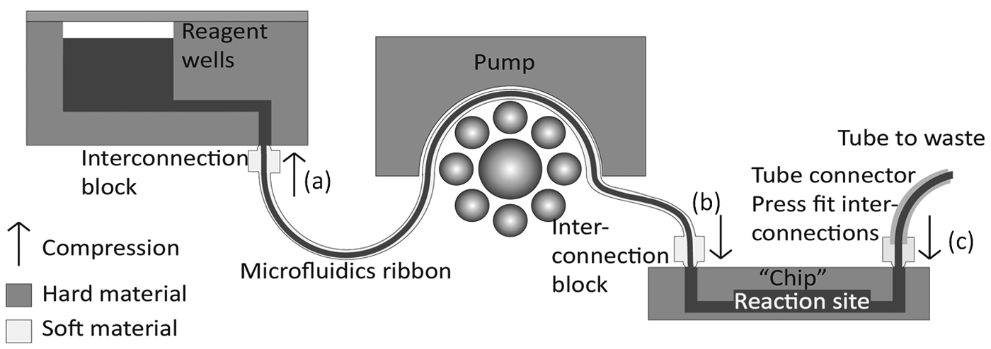
Schematic sample-to-waste and interconnection principles for MainSTREAM microfluidic systems. In this example, a sample well is connected to a micropump and then to a chip via a µFR. Waste is ejected from the chip through a tube connector. Typically, component locations are fixed on base plates. Exchanging a chip requires release of compression points (
Micropump Performance
The micropump is self-priming; it simultaneously pumps fluids through the eight channels of the attached type I µFRs and can do it in both forward and backward mode (
Valve Performance
The testing of the camshaft valve is described in detail in the supplemental information. The valve was able to block fluid flow in channels against an upstream micropump running at 100% motor power. With an open valve, this corresponds to a flow rate of 89 µL/min, which is well above that used for the majority of microfluidic applications. The pressure buildup between the micropump and valve was automatically relieved by a backflow toward the micropump. Valve rotation between different positions occurred in less than 2 s. During rotation, all eight valves were controlled simultaneously. The camshaft valve disk configuration determines which lines are open and closed, respectively, after rotation of the camshaft to a new position. A small burst of liquid could be observed for the newly opened line, which is caused by the rotation of the valve or the pressure buildup that is released when the line is opened. Valve durability testing (see supplementary information) was voluntarily stopped after 20 000 rotations. In this test, each rotation corresponds to an opening and closing of each of the eight channels of the µFR. During this testing, it was found that the µFR was not damaged, and all eight channels were still being properly valved. Given that the testing was voluntarily stopped after 20 000 rotations, this is likely an underestimate of durability. For typical biochemical assays (see Discussion), this is sufficient for approximately 2000 complete assays.
Allele-Specific Hybridization Genotyping
We have previously described the incorporation of DNA arrays within PMMA-based microfluidic chips
25
to genotype patients for mutations in the HBB gene, which gives rise to beta-thalassemia. HBB mutations are prevalent in resource-poor areas, where a key requirement for diagnostics is low cost. One way to achieve this is to increase the number of tests and patients analyzed per device. The microfluidic lanes of our previously developed DNA chip were addressed with a pipette and using 4.5-mm channel spacing. In general, reduction of feature spacing increases cross-contamination risks. To avoid this, the original microfluidic DNA chip
25
was modified using the MainSTREAM’s standard 10-hole pattern and connected to two hand crank–driven micropumps (
Fig. 6
and
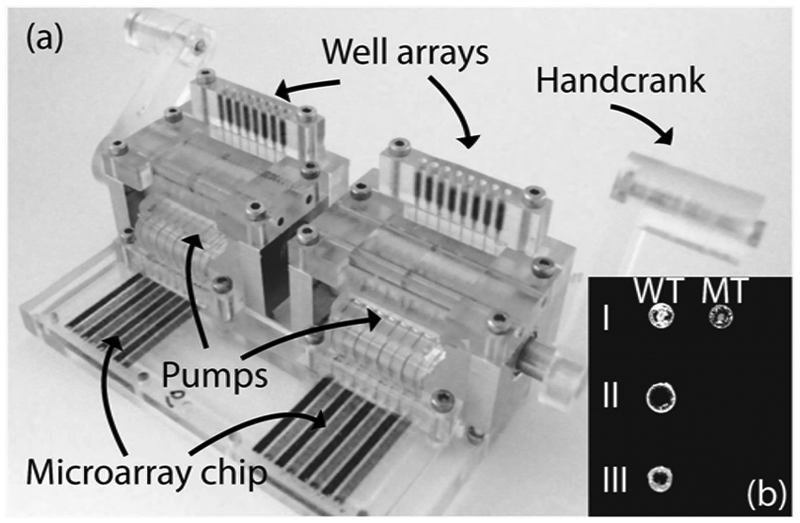
MainSTREAM allele-specific hybridization (ASH) genotyping. (
The WA chips (
Figs. 4
and
6
), attached directly to the type I µFRs of the pumps, provide features that guide the operator and are more suited for introduction of solutions by a pipette. With this new configuration, genotyping can now be achieved on chips featuring 16 lanes spaced at 2.25 mm (
Fig. 6
). The inserted PMMA chip (
Fig. 6a
) contains a microarray of DNA probes (
In Situ Hybridization
ISH assays are histological assays that are used in pathological investigations, aiming at detecting the presence of various diagnostic markers (e.g., nucleic acid sequences) within preserved tissue sections. The lack of reproducibility of conventional histological assays is currently limiting their clinical relevance and potential. 30 This irreproducibility stems from variability in processing steps, such as sample pretreatment and hybridization conditions.31,32 In addition, the utility of ISH assays is limited as they typically are manually operated and take a long time to complete (from one to several days). For instance, to stain microRNA-138 (miR-138) in the conventional way requires incubation of the tissue slide with eight different reagents and 18 incubation and washing steps. 28 We recently developed the HistoFlex device as a tool for generating high-performing histological assays. 28 It comprises a patterned PDMS insert, which upon assembly seals a microfluidic reaction chamber to a tissue section fixed on a microscope slide. HistoFlex enables real-time monitoring of flow-based assays over tissue sections and reduces the variability related to hybridization conditions. However, as a stand-alone device, it still required manual and sequential introduction of reagents. To obtain automation related to sample introduction and to reduce ISH assay time, the HistoFlex device was interfaced to a MainSTREAM system ( Fig. 7 ). The reagents required for the ISH assay were placed in reagent vials that were connected to the micropump by a TC. The micropump was then connected to the camshaft valve using a connector chip (CC). As the HistoFlex is not part of the MainSTREAM component platform, its interconnection features are not directly compatible with MainSTREAM components.
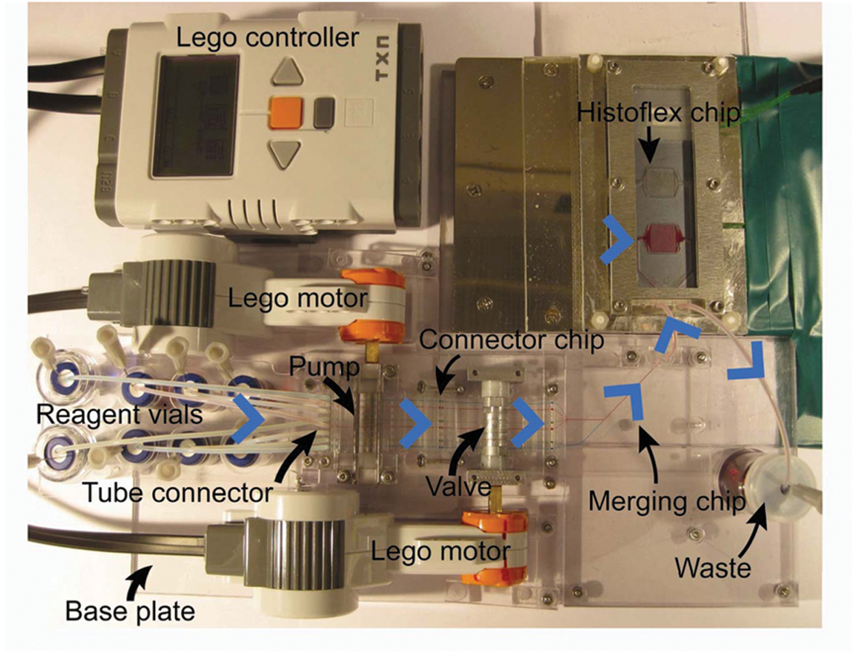
In situ hybridization (ISH) assay: system. All components except the computer controller were attached to a base plate. The µFR of the pump was connected to the µFR of the valve with a connector chip. Reagents are stored in the vial rack prior to usage. Reagents flow (blue arrows) from the vials through the micropump and toward the valve. They are then routed into two channels (six channels in one and two channels in the other) through the merging chip and then merged into a single channel before entry into the HistoFlex. A program automates the assay by coordinating and controlling the motors used for micropump and valve operation. For visualization, the micropump and camshaft valve channels are filled with either water or colored dye solutions (blue, green, and red). The HistoFlex reaction chamber is filled with red dye. Excluding the HistoFlex temperature control components, the system footprint is approximately 30 × 20 cm.
To solve this, an MC (
Fig. 7
) with the 10-hole pattern, permitting connection to the camshaft valve, was connected to the HistoFlex (
Fig. 7
) using a press-fit connection. The LEGO Mindstorms motors and software interface were used to control the micropump, camshaft valve, and hence gate and automate the introduction of eight different solutions into the HistoFlex. In brief, the micropump was programmed to run at 89 µL/min (full speed) when filling or replacing reagents in the reaction chamber of the HistoFlex (
Using the system shown in Figure 7 , an ISH assay was performed for detection of miR-138 in FFPE mouse brain tissue sections by adapting the protocol previously described by Søe et al. 28 Results of the ISH assay are shown in Figure 8 . Automation of the ISH assay using the MainSTREAM platform resulted in the reduction of assay time to approximately 4 h, which is half the time of conventional methods, 28 and, with the exception of initial sample vial filling, eliminates the need for an operator.
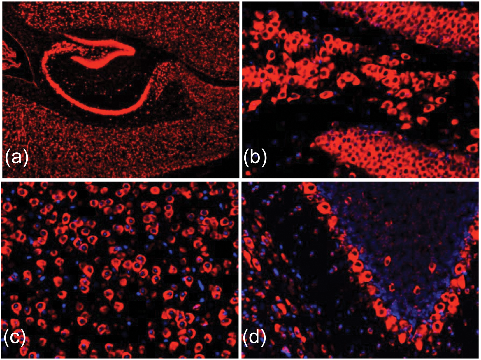
In situ hybridization (ISH) for detection of microRNA-138 in mouse brain tissue sections. Fluorescent images show miR-138 in red (cy3) and nuclei in blue (DAPI). (
Cell Culture and Differentiation
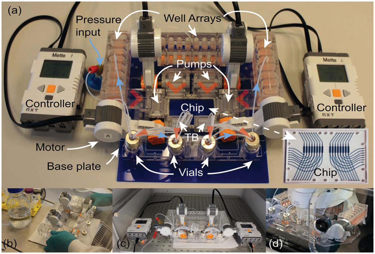
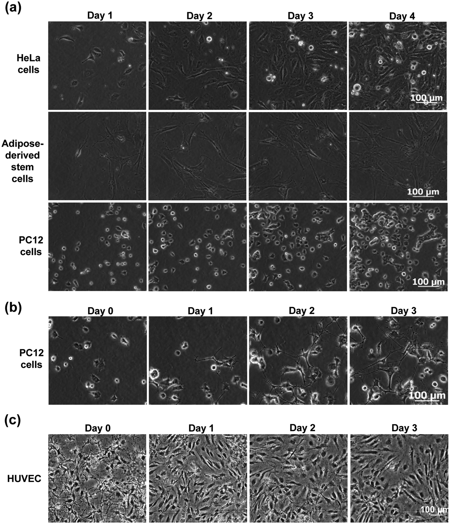
Compared with the assays above, cell culturing is a more demanding application as it requires MainSTREAM components to be biocompatible, as well as able to maintain a sterile environment and to support long-term experiment (days to weeks). A MainSTREAM multi-micropump system with 32 fluidics inputs and 16 fluidics outputs to and from a reaction chip ( Fig. 9 ) was used for culturing of HeLa cells, adipose-derived stem cells, PC12 cells, and HUVECs over a period of 4 days ( Fig. 10 ) in a 16-chamber reaction chip ( Fig. 9 ). PMMA was used due to its biocompatibility.33,34 HeLa cells proliferated as rapidly in MainSTREAM systems as in cell culture flasks (data not shown). HeLa cells cultured in the MainSTREAM system ( Fig. 10a ) had the same morphology as HeLa cells grown in cell culture flasks (data not shown). ASCs ( Fig. 10a ) grew well in MainSTREAM systems as compared with microtiter plates (data not shown). ASCs could also undergo a 3-week-long differentiation process in MainSTREAM systems (M Hemmingsen, S Vedel, P Skafte-Pedersen, A Sørensen, P Collas, H Bruus, M Dufva; unpublished results). Morphologically, PC12 cells respond to NGF, stimulating them to differentiate and stop dividing, which make them useful as a model for neuronal differentiation. After 4 days of cell culturing of PC12 cells in normal cell culture medium, differentiation was initiated by filling the liquid reservoirs in MainSTREAM systems with differentiation medium. The cell differentiation was followed by time-lapse microscopy every 6 h for 3 days, showing an increasing network of axons ( Fig. 10b ), which demonstrates that the system is usable for PC12 cell differentiation and for on-stage time-lapse microscopy. PC12 cells cultured for 4 days in cell culture medium did not differentiate ( Fig. 10a ). HUVECs were used as a cellular model for culturing of primary cells in a MainSTREAM system. These primary cells adhered and proliferated, and morphology ( Fig. 10c ) was similar to HUVECs cultured in commercially available IBIDI chips connected to a commercial peristaltic pump (data not shown).
(
Cell adhesion, proliferation, and differentiation studies in the MainSTREAM system in
Figure 9
. (
A cell culture experiment took on average 10 h to start in a MainSTREAM system with 16 to 24 parallel fluidic inputs. In contrast, an experiment with a chip connected to syringe pumps with tubing took 10 h for only 4 fluidic inputs. Thus, the MainSTREAM design reduced time to start a parallel experiment to about 30 min per reaction chamber as compared with 2.5 h for a chip and syringe pump solution.
Failures during operation were typically of two types: bubble formation and leaks. Chips driven in the MainSTREAM system, without overpressurizing the entire system, lead to bubble formation in the majority (70%) of the reaction chambers even after only a few days of cell culturing. Similarly, the chip and syringe pump–based cell cultures had about 50% chambers containing bubbles. Pressurizing the MainSTREAM system resulted in bubble-free operation for periods greater than 3 weeks of culture. Leaks were mostly caused by delamination of bonded chips and breaks/tears in the µFR (data not shown). These were usually discovered during system assembly and priming, and remedy and elimination of leaks attributable to MainSTREAM µFRs was as simple as exchanging for a new µFR. It should be noted that an assembled leak and bubble-free MainSTREAM system always (11 out of 11 long-term experiments) remained free of leaks, bubbles, and microorganism contaminations despite being moved about 20 times during a 3-week cell culturing experiment. These movements were necessary to switch medium and to transport the microfluidic system between workstations, including detecting cell growth by microscopy ( Fig. 9 ).
Discussion
The goal was to create a modular microfluidic component platform for constructing microfluidic systems for biological applications such as parallel cell culture, genotyping, or in situ hybridization. MainSTREAM provides (1) a rapid, robust, and simple method to establish numerous fluidic inputs and outputs to various types of reaction chips; (2) highly parallel pumping and routing/valving capability; (3) methods to interface pumps and chip-to-liquid management systems; (4) portability; (5) reconfigurability/flexibility in system design; and (6) compatibility with microscopy and (7) biocompatibility. Existing modular microfluidic systems (www.epigem.co.uk; www.labsmith.com; www.thinxxs.com)8–13 are based on a standardized breadboard base plates into which elements (usually just chips) are plugged in. The underlying assumption of this type of approach is that the breadboard’s spacing and other design criteria will satisfy the overwhelming majority of microfluidic application and assay requirements. The MainSTREAM components are, on the other hand, modular and reconfigurable, and they provide a method to establish many different fluidic systems suitable for many types of applications. As shown ( Figs. 6 , 7 , and 9 ), each application requires a widely different layout of the system, suggesting that a standard breadboard is more appropriate for rapid prototyping of chip functionalities (e.g., by serial connection of standardized chips) but not for prototyping or construction of entire microfluidic systems.
The performance of the presented modified peristaltic micropump is sufficient for many if not most biological microfluidics applications and performs similarly to commercial syringe pumps with respect to channel-to-channel variability.
21
The significant improvement in durability compared with our previous pump
21
makes it particularly suited for extended experiments, such as long-term cell culture. Direct comparisons to similar PDMS-based mechanically actuated peristaltic pumps are difficult to make as these present only a single-channel pump35–38 or do not provide comparable data.19,39 The MainSTREAM micropump facilitates parallel operations on a chip with very small dead volumes. This is especially useful for multiplexed experiments where sample conservation is desired. The flow rate range, from sub-µL/min to near 90 µL/min, is appropriate for most applications where the reaction chamber is on the order of a few microliters to several tens of microliters. The peristaltic pulsating flow does not seem to affect the fluidic operations on the chip, such as switching from one fluid to another
22
or influencing the cell or solid-phase biochemical assay performance (
Figs. 6
–
10
). In some cases, the pulsation may even be an advantage, as it more closely mimics physiologically relevant phenomena like the pulse caused by a heartbeat. Compared with previously reported solutions,
22
the use of the Mindstorms equipment increases the portability, availability, and simplicity of actuation. The reason is that Mindstorms provides a commercially available and inexpensive solution that can be applied directly without further modifications or programming. Moreover, the ability to drive the micropump at high flow rates is an advantage for assays such as ISH (
Figs. 7
and
8
). For the ISH protocol, exchanging reagents as quickly as possible within the reaction chamber took only 20 s. Corresponding time with the previous solution
22
would have taken about 6 min, which would significantly increase the time it would take to make multistep in situ hybridization assays. The integrated rotation sensors of the Mindstorms motors are very suitable for operation of the camshaft valve and allow programming of discrete volume delivery from the micropumps. This feature is used in low-volume perfusion of cell cultures. For instance, to obtain an average perfusion rate of 33 nL/min, the motor was programmed to turn 1 degree every 4 s at 30% power. For perfusion with 500 nL/min, the motors turned 1 degree every 0.17 s at 30% power (see also
The novel camshaft valve presented in this report is itself a reconfigurable component, which coordinates opening and closing of all the µFR channels simultaneously. Unlike many other valves that employ deflection of elastomeric membranes,16,40–44 the MainSTREAM valve is located outside and apart from the microfluidic chip it addresses (as is the peristaltic micropump). Compared with the use of screws,44,45 the camshaft in our valve simplifies operation as it coordinates valving of multiple channels simultaneously. As an example, an eight-channel system passing from an “all open” to an “all closed” configuration with screw-based valves requires manual adjustment of eight individual screws. In contrast, the camshaft only needs to be rotated to a new position ( Fig. 3 ). Solenoids or piezoelectrically driven tactile pins could have been used to valve individual channels of the µFR rather than a DC motor-controlled camshaft. However, doing so would add additional layers of actuation and control equipment. In addition, the use of solenoids restricts the system portability. 7
The MainSTREAM design concept enables construction of highly integrated systems to which microfluidic chips can be attached and exchanged. This very much resembles how POC systems and devices are used. The resulting portable MainSTREAM systems are well suited in cases where the system must be transported between different laboratory areas. This is illustrated by the cell culture system in Figure 9 . The described cell culture experiments required movement between different stations (LAF benches, incubators, and microscopes) up to 20 times during an experiment. The robust nature of the system during moves stems from (1) simple disconnection of electrical contacts (unplugging electrical connector cable of LEGO motors); (2) valve-like functionality of the micropump when stopped; (3) low-pressure buildups in the short tubes of µFR, thereby preventing and limiting unwanted fluid flows; and (4) maintenance of all fluidic connections, which is very important for avoiding introduction of bubbles. The portability is partly the reason why MainSTREAM systems for cell culture seem to be efficient in keeping microorganism contamination away. MainSTREAM systems are a fully closed system during operation, meaning that there are no openings to the outside from liquid input to liquid output during operation. Connection integrity from input to output was tested by submerging an assembled system ( Fig. 9 ) without motors in water. During incubations, movement, and microscopy (Fig. 9c, d ), there is therefore no possibility for microorganisms to enter the culture systems. The largest contamination risk is probably during system assembly, cell loading, and medium exchange. However, as the system is fully portable, these operations can be performed in the LAF bench ( Fig. 9b ).
To provide professional scale analysis systems that meet parallellization, multiplexing, and throughput demands, many inputs and outputs to a microfluidic device or chip should be provided. The number of samples analyzed in a reaction chip is limited by the number of unique reaction mixes that can be delivered to different reaction sites on the reaction chip. The degree of limitation is set by the number of individual pump lines to a passive reaction chip (used in MainSTREAM systems) or pumping and valving capacity on active reaction chips (used in the MLSI and Braille display approach). Commercial producers of microfluidic systems and components such as ThinXXS and Dolomite provide miniaturized pumps and valving solutions, but they address only a single channel but occupy a similar footprint size as the MainSTREAM’s eight-channel micropump or valve. As shown here, further miniaturization of components allows for construction of compact and portable yet highly parallel microfluidics systems with integrated pumps, valves, reagent and waste management, and motors ( Figs. 6 , 7 , and 9 ). However, it is unlikely that the MainSTREAM systems can match the multiplexing and throughput capabilities of the multilayer elastomeric approaches, such as the MLSI14–16 or Braille display17–19 systems. For example, a single camshaft valve cannot produce as many valve combinations as the MLSI and Braille methods. However, for many applications, the ability to generate this many combinations is not required. 44 The simple valve sequence used in this report, which gates one of eight liquids at a time through a reaction chamber, suffices for many different biochemical and cell-based assays such as sandwich, competitive, and direct immunoassays; DNA, protein, and small-molecule analysis by microarrays; tissue section analysis ( Figs. 6 and 7 ); affinity-based sample preparation procedures; and the stepwise addition of compounds required to differentiate stem cells. 46 With respect to assays featuring parallellization, recent MLSI-based microfluidic high-content methods employ 16 fluidic inputs, excluding inputs required for system control,14,15 capable of routing to different parallelized cell culture sites 14 and leading to 256 unique experiments. The MainSTREAM system shown in Figure 9 has 32 fluidic inputs. In principle, it would be possible to arrange the pumping capacity into a similar combinatorial fashion, also reaching 256 different unique reaction sites. This number of fluidic inputs pushes the limitations of microfluidic approaches away from fluidic concerns and toward those associated with data capture and analysis. For example, time-lapse data capture and analysis of 32 parallel cell cultures simultaneously will be demanding.
There is currently a need for standardized, cheap, interconnectable, and easy to build microfluidic systems. 5 MainSTREAM meets these demands. The components presented in this report are low cost and are built from affordable materials (e.g., the material cost for micropump and camshaft is approximately U.S.$10 each). MainSTREAM also uses a standard 10-hole pattern for fluidic input/output of eight channels. Although overall chip dimensions are flexible with this approach, the chips presented in this report were of single or double microscope slide size to facilitate use in standard processing, such as microarray spotters and microscopic equipment. 25 The spacing of the µFR channels was set at a 1536-well plate standard (2.25 mm) to simplify future coupling to automated robotic handling systems.
In conclusion, the MainSTREAM component platform is compatible with biological assays, provides a standardized method to robustly and easily connect microfluidics chips to pumps and reservoirs, and provides possibilities to pump a large number of different liquid streams into a microfluidics chip. MainSTREAM is therefore a highly usable platform for automated parallel liquid handling for microfluidics applications.
Footnotes
Acknowledgements
The adipocyte derived stem cells were a kind gift of Prof. Philippe Collas, University of Oslo.
Declaration of Conflicting Interests
The authors declared no potential conflicts of interest with respect to the research, authorship, and/or publication of this article.
Funding
The authors disclosed receipt of the following financial support for the research, authorship, and/or publication of this article: This work was supported by grant no. 2106-08-0018 “ProCell,” grant no. 2106-05-0047 “BioXTAS,” and grant no. DSF- 09-067112, under the Programme Commission on Strategic Growth Technologies; the Danish Agency for Science, Technology and Innovation; and EU FP7 grant agreement no. NMP4-SL-2008-214706 “EXCELL.”
References
Supplementary Material
Please find the following supplemental material available below.
For Open Access articles published under a Creative Commons License, all supplemental material carries the same license as the article it is associated with.
For non-Open Access articles published, all supplemental material carries a non-exclusive license, and permission requests for re-use of supplemental material or any part of supplemental material shall be sent directly to the copyright owner as specified in the copyright notice associated with the article.