
Abstract
Boehringer Ingelheim’s Automated Liquids Processing System (ALPS) in Ridgefield, Connecticut, was built to accommodate all compound solution-based operations following dissolution in neat DMSO. Process analysis resulted in the design of two nearly identical conveyor-based subsystems, each capable of executing 1400 × 384-well plate or punch tube replicates per batch. Two parallel-positioned subsystems are capable of independent execution or alternatively executed as a unified system for more complex or higher throughput processes. Primary ALPS functions include creation of high-throughput screening plates, concentration-response plates, and reformatted master stock plates (e.g., 384-well plates from 96-well plates). Integrated operations included centrifugation, unsealing/piercing, broadcast diluent addition, barcode print/application, compound transfer/mix via disposable pipette tips, and plate sealing. ALPS key features included instrument pooling for increased capacity or fail-over situations, programming constructs to associate one source plate to an array of replicate plates, and stacked collation of completed plates. Due to the hygroscopic nature of DMSO, ALPS was designed to operate within a 10% relativity humidity environment. The activities described are the collaborative efforts that contributed to the specification, build, delivery, and acceptance testing between Boehringer Ingelheim Pharmaceuticals, Inc. and the automation integration vendor, Thermo Scientific Laboratory Automation (Burlington, ON, Canada).
Analysis of Compound Management Processes
Prior to the Automated Liquids Processing System (ALPS) project, generation and maintenance of high-throughput (HTS) library and concentration-response sets was a labor intensive, batch-based process with multiple distinct operations. Because processes relied on a manual presence to move plates between workstations in separate laboratories, production was limited to core employee hours and humidity control was not feasible. Operations preceding plate-to-plate transfers included but were not necessarily limited to centrifugation, unsealing/piercing, and labeling. Source plates were manually centrifuged to ensure liquids did not cling to seal material and to mitigate air bubbles prior to transfer. Individually, source compound plates were manually unsealed if in a 96/384 fixed-well plate format. Alternately, source 96/384 punch tube plates were pierced singly using a Remp Universal Plate Piercer (Brooks Automation, Inc., Chelmsford, MA). If pretransfer DMSO dilution was required, plates were manually loaded onto broadcast dispensers equipped with stacking capability (Zoom MV; Titertek Instruments, Huntsville, AL). Likewise, if destination plates were part of a dilution series set, DMSO was also dispensed using the Zoom MV. Destination plates, if not prelabeled with a barcode by the manufacturer, were manually stacked onto a CyBi-Print Vario print-and-apply barcode station (CyBio US, Inc., Woburn, MA). Once all prerequisite steps were complete, source compound plates and destination plates were manually stacked onto the CyBi-Well Vario 96/384 disposable tip pipetting system (CyBio US, Inc.) for various plate-to-plate transfer and mix procedures. The CyBi-Well Vario was equipped with barcode scanners to generate text reports for source-to-destination plate transfer relationships. These text reports were required for registering newly created plates in a sample management database. The CyBi-Well Vario was outfitted with unattended disposable pipette tip-changing capabilities to afford limited walk-away time. Following plate-to-plate compound transfers, newly created fixed-well plates and punch tube plates were manually delivered to various stacker-based instruments for application of thermally applied seals. Once sealed, some completed plates were collated on bench tops into groups for delivery to downstream HTS systems. Other completed plates were left noncollated and manually loaded into a Remp Large Size Store (LSS) Automated Storage System (Brooks Automation, Inc.). This examination of prior manually mediated compound management processes highlighted significant gaps and inefficiencies for improvement. The desire to eliminate intermediate manual steps and to significantly improve capacity for overnight processing, all while sustaining sample quality in a humidity-controlled environment, was seen as impetus for the ALPS project.
Concept to Specification
From the analysis of existing batch-based operations, a broad project outline emerged for ALPS. Amalgamated process flow concepts were formalized into a request-for-proposal (RFP) document inviting vendors to offer automation solutions. The RFP explained distribution processes using various plate types, replicate counts, dilution series, and volumes that would later serve as templates for detailed acceptance tests. The RFP called for integrating the following plate processing instruments: VSpin plate centrifuge, VCode barcode print applicator, and PlateLoc plate sealer (Agilent Technologies, Santa Clara, CA); Remp Automated Plate Piercer (APP), Nexus XPeel automated plate seal remover, and Remp CSP384 tube sealer (Brooks Automation, Inc.); Zoom MV broadcast dispenser (Titertek Instruments); Multidrop Combi-nL broadcast dispenser (Thermo Fisher Scientific, Waltham, MA); and CyBi-Well Vario 96/384 pipettor (CyBio US, Inc.). Potential vendors responded with written and oral presentations proposing robotic integration of these instruments to fulfill processes as defined in the RFP workflows. Vendor proposals provided concepts for numerous issues such as plate transport, plate storage, software interfacing and programming, data handling, safety, project management, timelines, costing, and field service. Following the RFP review process, working in collaboration with internal purchasing agents, Thermo Scientific Laboratory Automation (Burlington, ON, Canada) was chosen as the integration vendor for the ALPS project. Collaboration with this integration vendor generated 14 conceptual draft iterations for equipment integration and functionality before final specification. When documentation was complete, ALPS was specified to handle all postdissolution liquid-processing steps in 96/384/1536 fixed-well formats and 96/384 punch tube formats, generating plates for both long-term storage and direct handoff to internal customers. ALPS was also specified with placeholders for future high-density 1536/3456-well compatible equipment.
The main concept that drove the specification was an assemblage of hardware components operating as two independent and nearly identical subsystems ( Fig. 1 ). Alternately, if more complex needs arose, the two subsystems could be reconfigured to operate as one larger and unified system via an intersystem “link” robot. The dual subsystem approach provided greater flexibility in scheduling for routine maintenance and new process development since either could execute processes interchangeably. In addition, in the event of essential equipment failure, daily operations could continue on the alternate subsystem. In the event that additional throughput was required, two functioning subsystems could execute identical processes to double the intended output.
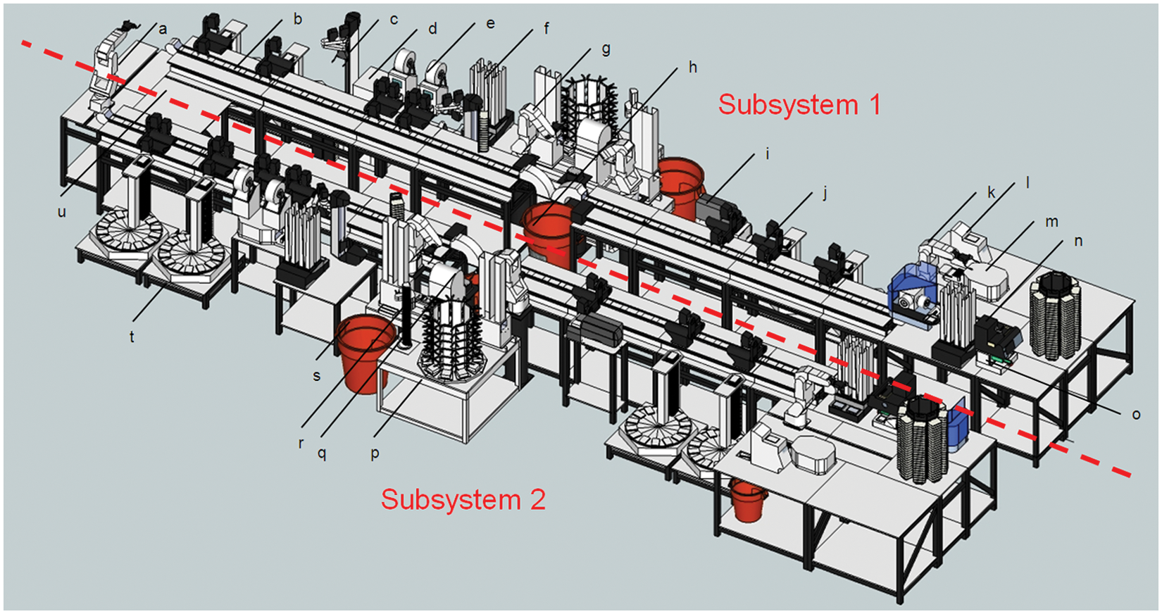
Automated Liquids Processing System (ALPS) concept model. Collaboration with the integration vendor, Thermo Scientific Laboratory Automation, used 3D modeling tools to conceptualize ergonomics, safety, laboratory traffic, service, and maintenance issues. The concept-to-specification stage led to a design with two nearly identical subsystems that could operate independently or alternatively as a larger unified system for complex operations. Once concepts were finalized, Thermo Scientific Laboratory Automation produced engineering drawings required for specification and system build. Identified equipment: (
The two subsystems, separated by a middle service alley, had minor dissimilarities in the overall equipment layout because equipment ran parallel and facing opposite to each other, thus creating some plate-loading asymmetries between identical instruments. For example, on subsystem 1, plates flowed left to right through the CyBi-Well Vario, but on subsystem 2, this occurred right to left. Dissimilarity also occurred because one subsystem lacked a Remp CSP384 tube sealer due to budgetary considerations. However, a place holder location within subsystem 2 was reserved for a future Remp CSP384 tube sealer.
Each subsystem was designed to operate under separate computer control. All instruments communicated via a central serial port expansion system or via Ethernet protocol and were accessible by both subsystem control computers. When configured as a large unified system, one computer system controlled all instruments, with the other computer system not employed. This reconfiguration was specified to occur by selecting a different instrument profile in the operations and scheduling control software, Momentum 3.0 (Thermo Scientific Laboratory Automation). To keep reconfiguration quick and simple, no hardware changes or relocation were permitted in the specification. As a specification metric for ease of use, implementation of this reconfiguration by the operator was required to take place in 5 min or less.
System Throughput
Analysis of all process steps revealed that each piece of equipment could perform required tasks at a rate of 1 min or less. For ALPS to achieve this throughput, concepts focused on rapid robotic transport to ensure devices would have bare minimal idle time waiting for plate transport. Instruments that approached the 1-min throughput mark, such as the CyBi-Well Vario and Remp CSP384 tube sealer, required nearby small-capacity storage locations to assist in rapidly advancing incoming and outgoing plates. Also as means of reducing cycle times, several pieces of equipment required development of “prepare-to-access” operations in anticipation of plate transit. For example, MicroServe plate storage carousels (High-Res Biosolutions, Woburn, MA) were required to “prepare-to-access” to the next carousel position before receiving plates. This was relevant considering that MicroServe plate storage carousels were continually indexing to different stack locations to accommodate collation of replicate plate sets. Likewise, the CyBi-Well Vario employed a five-position plate indexing rail that also required anticipatory prepare-to-access moves to load and offload plates for best possible cycle times. With these optimization techniques, throughput requirements for most ALPS processes called for completing one newly labeled, sealed, and collated plate every 1 min or less.
Operational Capacity
Original concepts for ALPS envisioned sufficient plate storage capacity for round-the-clock unattended operation, only allowing sufficient time each day for an operator to offload completed plates, load new plates, refresh other consumables, and perform basic maintenance. Following process equipment selection and determination of a maximum 1-min per plate throughput, each subsystem was specified for a maximum capacity of 1400 plates. At a rate of 1 min for 384-well plate to 384-well plate transfers, including all ancillary pre- and posttransfer steps, each subsystem had capacity for nearly 24 h of unattended operation. The selection of the highly compact MicroServe plate storage carousels with capacities of 770 standard-height plates (14 mm) helped to achieve capacity goals. These units were equipped with 14 “first-in, last-out” storage racks, each capable of holding 55 plates. Since concentration-response processes were based on series generation of 10 dilution plates, the equipment was typically limited in configuration to an even 50 plates for operator ease of use. Each subsystem was specified with two MicroServe units as starting locations and two MicroServe units as final output locations. Accordingly, ALPS contained eight MicroServe units in total. Capacity was also augmented by two 200-plate capacity Presenter RS stack stores and a 90 deep-well plate capacity Microplate Carousel (both from Thermo Scientific Laboratory Automation) in each subsystem, typically used for handling source compound plates.
Output Plate Collation
With a maximum combined plate output of 2800 plates in a 24-h period, a major imperative was designing functionality to collate the indexed plates in each plate set into separate stacks. Using collation functions, operators could efficiently cull plate indices for delivery to internal customers. Each subsystem had the flexibility to collate across 28 separate stacks in MicroServe plate storage carousels, in addition to four stacks in a Presenter RS. In Figure 2 , Momentum 3.0 permitted user selection of collated output locations through a series of check boxes cross-referenced to each replicate in a plate set. Collation was specified for replicate plates to roll over to a second stack once a first stack was filled. Collation was not specified as an all-or-nothing option. Some replicates in a plate set could be collated for efficient grouping at the disadvantage of possibly not fully achieving stack capacity. Other replicates of the same plate set were co-mingled into noncollated common output stacks that could be filled completely before indexing to the next available noncollated output stack.
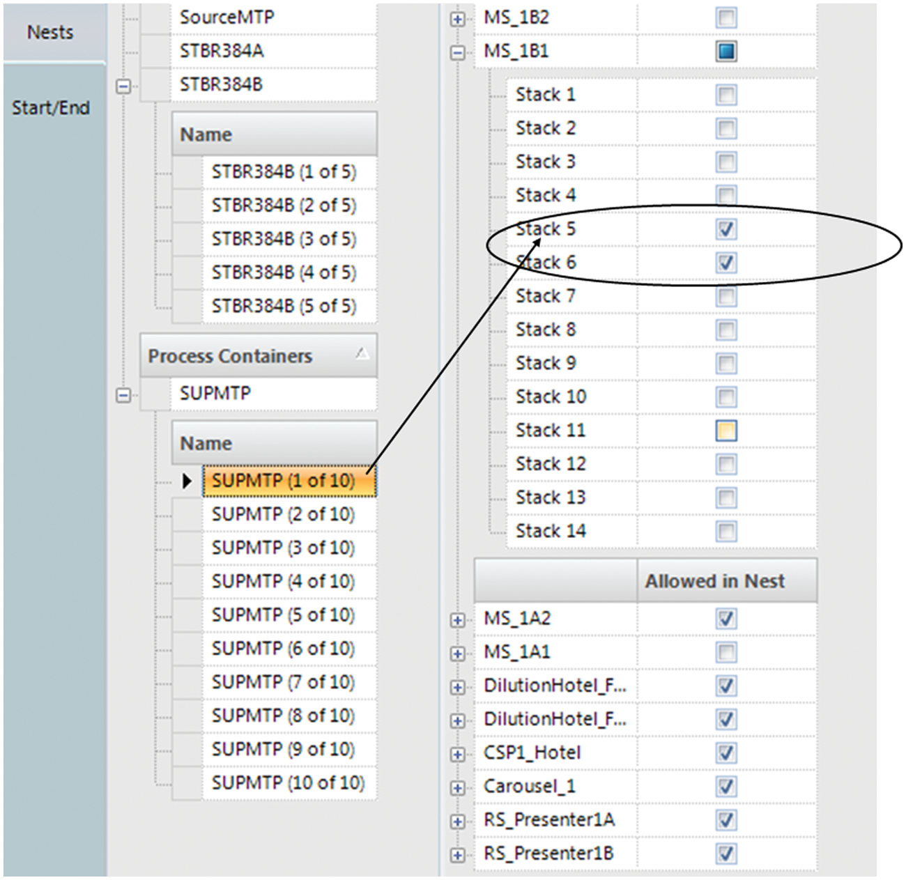
Collating completed plates into stacks is achieved by assigning allowable stack locations within a storage location. In this example, plate index 1 of 10 in a replicate set called SUPMTP is only allowed in specific output locations, stacks 5 and 6 of a MicroServe plate storage carousel (MS_1B1). The Automated Liquids Processing System (ALPS) would fill index 1 SUPMTP plates in stack 5 and subsequently in stack 6. Likewise, other plate indices of the SUPMTP set would be stored in other paired stacks to achieve collation.
Instrument Pooling
Instrument pooling was specified to aid in throughput capacity, collation, and instrument fail-over scenarios ( Fig. 3 ). Momentum 3.0 categorizes instrument pools into two types: storage pools and operation pools. Storage pools allow identical or dissimilar storage-type instruments to be grouped together to provide a larger combined storage capacity. Operation pools allow two or more identical instruments to be grouped together to provide increased throughput capacity and system redundancy. Both types provide different rules for instrument fail-over scenarios and device selection.
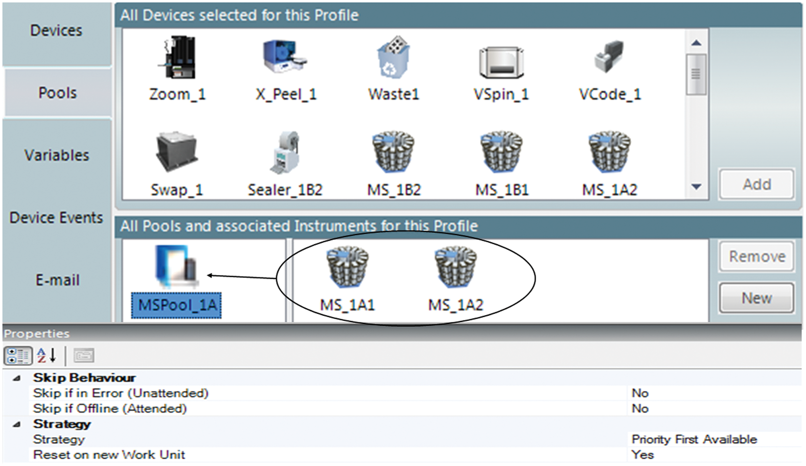
Storage pooling of instruments allows for expanded functionality as a single unit. Here two MicroServe plate storage carousels (MS_1A1 and MS_1A2) are grouped to increase capacity for collation of completed replicate plates. Operation pooling is also used with two PlateLoc plate sealers to keep a work unit running during a sealer failure event, albeit with reduced throughput.
Grouping MicroServe plate storage carousels into storage pools provided the benefit of collating one index of a replicate plate set into multiple stacks, even if in separate devices. ALPS was also specified with operation pools for twin plate sealers in each subsystem. In this case, the benefit was system redundancy if one plate sealer encountered an error. At the process level, all plates were destined for a plate sealer operation pool. Pooling rules determined which plate sealer was selected per seal cycle and also determined behavior in the event of a sealer failure. ALPS was configured typically to alternate between plate sealers so as to evenly consume reels of sealing material. In the event of equipment failure, all plates would continue to be processed by the remaining sealer, with the system running at reduced throughput.
Compound Solutions Transfer
At the heart of ALPS functionality was compound transfer of solutions in source 96/384-well plates to replicate 96/384 fixed-well and 96/384 punch tube plates using the CyBi-Well Vario. The CyBi-Well Vario was equipped with an automated pipette tip exchange option, composed of a KiNEDx arm (Peak Robotics, Colorado Springs, CO), a 90-position tip-cartridge carousel, and a tip-cartridge disposal ( Fig. 1p – s ). Automated pipette tip exchange was designed to permit users to reload the tip-cartridge carousel without stopping instrumentation. Two F5 robots (Thermo Scientific Laboratory Automation), one on either side of the CyBi-Well Vario, were specified for plate delivery ( Fig. 1g ). The selected CyBi-Well Vario model had five robot-accessible linear plate nest locations. Each F5 robot could access three of five CyBi-Well Vario nest locations, with only the middle position accessible by both F5 robots. One F5 robot could deliver a replicate plate to the middle CyBi-Well Vario nest location for pipetting, followed by the other F5 robot quickly removing it for downstream operations. This middle plate location was typically reserved for rapidly exchanging voluminous numbers of replicate plates, whereas other CyBi-Well Vario plate nests were typically specified for source compound plates or intermediate dilution plates far fewer in quantity. To aid in system throughput and flexibility, source and replicate plates were not necessarily scheduled for concurrent positioning at the CyBi-Well Vario. Therefore, pipette transfer scripts were broken into discrete functions for each plate. For example, a source compound plate could be delivered to the CyBi-Well Vario for script execution of an aspirate command. Then, liquid could be held in the disposable pipette tips as multiple replicate plates passed quickly through the CyBi-Well Vario, each triggering script execution of a dispense command.
Plate Transport
ALPS was configured with four conveyor belt instruments called Linear Plate Transports (LPTs) (Thermo Scientific Laboratory Automation) ( Fig. 1b ). Two LPTs, positioned end-to-end, functioned within each of the two parallel positioned subsystems. Two F5 robots were positioned in between end-to-end LPTs within each subsystem, with pivoting plate swap nests serving as hand-off positions ( Fig. 1g ). Waste receptacles were positioned at the terminus of each LPT for roll-off disposal of plates ( Fig. 1h ). Overall, each subsystem’s two LPTs represented 32 linear feet of travel path for deploying plate-processing and storage instruments.
Selecting the most suitable local robotic plate transport to and from the centric LPTs was based on position, size, and accessibility of each peripheral plate-processing or storage instrument. F5 robots were selected for use in each subsystem’s source compound plate “preprocessing” area ( Fig. 1k ). Preprocessing areas required plate transport for shelf-based broadcast dispensers and vertical random-access storage positions. One additional F5 robot stood on a horizontal track, serving as an intersystem link between the two parallel subsystems ( Fig. 1a ). This permitted ALPS to serve optionally as one larger and unified system for complex operations. This F5 robot also served in a system area designated for future liquid-handling expansion ( Fig. 1u ). Significantly smaller and more cost-effective than the F5 robot, Flip Movers (Thermo Scientific Laboratory Automation) were employed for instruments positioned relatively close and level to the LPTs ( Fig. 1j ). Similar in design to the Flip Mover was the Vertical Array Loader (VAL) (Thermo Scientific Laboratory Automation), which accessed instruments with plate nests positioned in locations much lower than the LPTs ( Fig. 1c ).
With a topology of multiple transports between processing and/or storage instruments, Momentum 3.0 used coordinated motion architecture to move plates without hesitation. When plates were scheduled for pickup and transport to subsequent locations, each mover was resource locked and dedicated before motion began. Therefore, virtually no delay occurred between the multiple moves. Programmatically, operators were required to select only the destination location, without explicit creation of multiple move sequences. Momentum 3.0 would calculate the destination path.
Process Scripting and Control
Transfer, dilution, and reformatting projects continually emerge in a compound management environment. The ALPS specification required capability for operators to draft automation protocols without computer programming expertise. High-level scripting languages were exchanged in favor of a paradigm using programmatic flowchart design. Momentum 3.0 used in-depth vertical flowchart design to describe automated plate-processing and storage steps ( Fig. 4 ). The Momentum 3.0 flowchart scheme represented the path of one instance of one or more plate (container) sets moving through a protocol from beginning to end. As instrument resources became available during a batch, the Momentum 3.0 scheduler then overlaid subsequent instances based on a selected batch size. In a typical 1:N plate replication scheme, the source compound plate would be operator selected for a plate set size of 1 with associated replicate plates having an N plate set size. This 1:N plate transfer association is depicted in Momentum 3.0 flowchart programs as a loop structure ( Fig. 4d , e ).
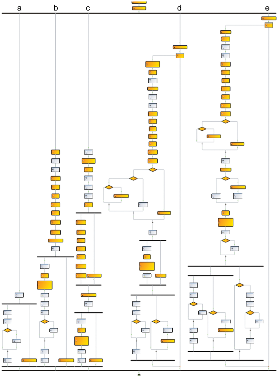
Momentum 3.0 programmatic flowchart using parallel path processing. The five lanes depict operational parallel paths of five plate types: (
Momentum 3.0 can execute concurrent process steps as depicted by branching parallel paths in a flowchart program. Parallel paths are required to reach a downstream merge point where both branches must complete before advancement to subsequent process flowchart steps. Concurrent parallel paths were designed to run either independently or dependently of one other. In a dependent approach, one branch of concurrent parallel path event-gates the progress of another branch. Flowchart control elements called “acquire key” and “release key” are employed. One branch would release a key that the other branch needed to acquire before proceeding through a process gate. ALPS protocols frequently used these dependent keyed gates in parallel paths to control the advancement of different plate sets to target locations. This strategy was deployed in complex protocols to make flowchart design leaner and more tightly coordinated. For example, a typical compound plating scheme required one 384-well compound source plate, one replicate 384 punch tube plate, one 384-well dilution plate, one plate set of ten 384-well replicate plates generated from the dilution plate, and one set of five replicate 384 punch tube plates generated from the dilution plate. This complex protocol was reduced to five concurrent parallel paths, each representing one of the aforementioned plate set types. Each of the parallel paths could gate any other based on which path holds the keys to advance. The outcome was tightly coordinated “just-in-time” event-driven programs that contributed to accomplishing specified throughput goals.
Decision-based logic control in Momentum 3.0 flowchart processes was depicted by traditional diamond-shaped condition symbols. ALPS frequently used these “if-then” controls to determine optional process paths. For example, decision branching was employed to execute slightly different CyBi-Well Vario dispensing techniques for the last plate in a replicate series. In another scenario, decision branching was programmed after each plate barcode scan to enable optional error trapping if mismatched codes were encountered.
Momentum 3.0 required expanded functionality for the manipulation of string text variables to handle ALPS barcode requirements. Variables are a programming mechanism to store assigned values in memory for recall in subsequent operations. In some processes, the acquisition of a source compound plate barcode was used to determine the scheme for printing subsequent replicate plates. To compose a replicate barcode identification, prefix and suffix characters from the source compound plate barcode were stripped off and substituted with a suffix series such as “A,” “B,” “C,” and so on. A substring function was used to extract root text from source compound barcodes, based on a start character position and substring character length desired. In addition, ALPS was required to have functionality to convert loop counter variables into alphabetical characters. For example, if looping through a set of 26 replicate plates, the program flowchart would generate a suffix variable equal to “A” on the first cycle and “Z” on the 26th cycle. ALPS also required a concatenation function for text string variables. By concatenating substring roots from the source compound plate barcodes with unique A–Z suffices derived from loop counters, newly assigned text string variables could be used to print unique barcode labels for replicate plates.
During system operation, each instrument could be displayed in a live Gantt chart depicting overall system activity for a time course ( Fig. 5 ). The Gantt chart was specified also to operate in simulated mode without any functioning instruments and with accelerated timing. Operators could simulate system topologies and scheduling scenarios for optimizing throughput and detecting programmatic errors before performing automated work units. Gantt charts were also designed as a review tool when recalling log files of past work units.
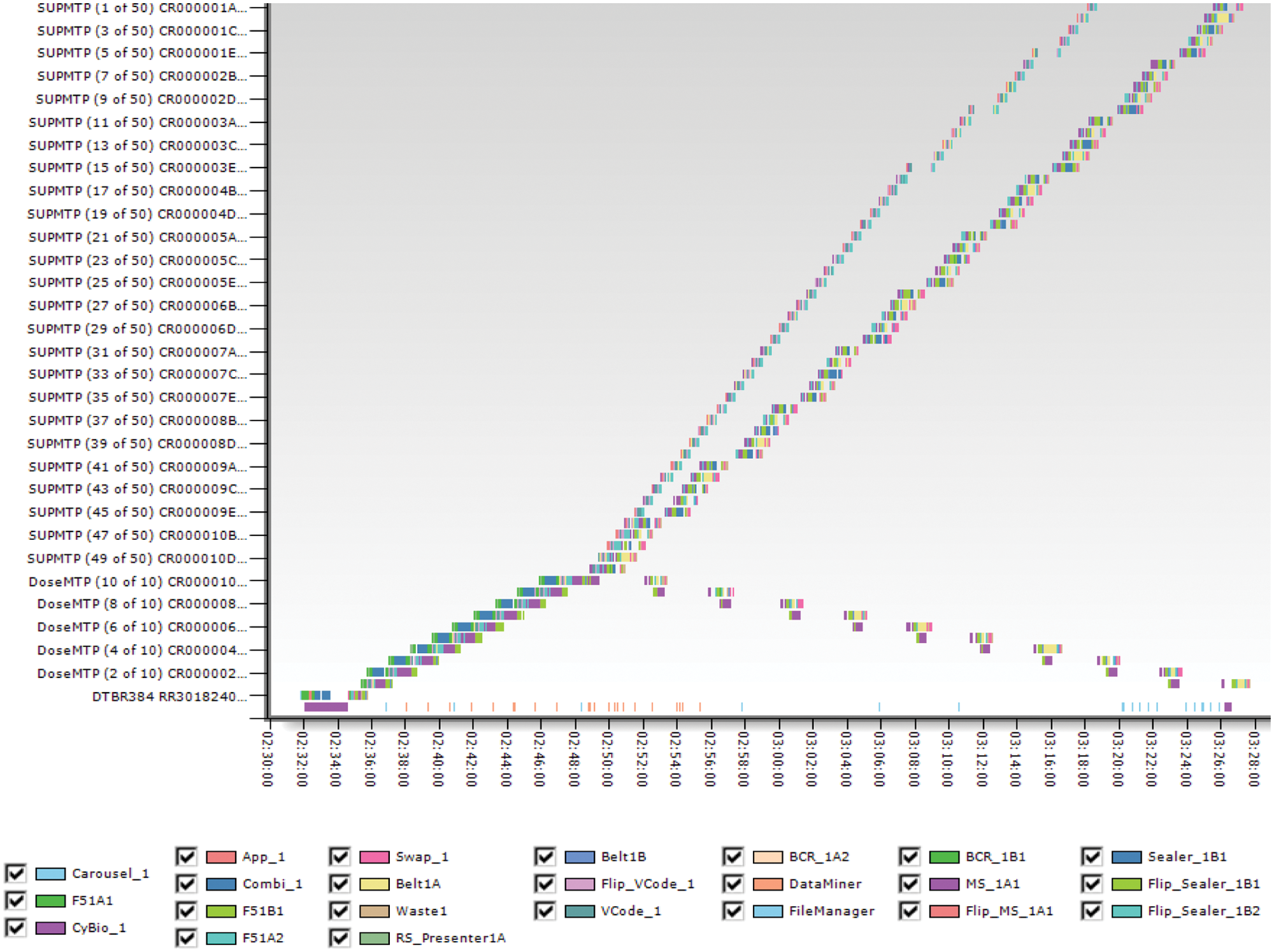
The Momentum 3.0 Gantt chart tool is used in accelerated-process simulations, during live operations, and in recalling historical logs. Operators can zoom into shorter time windows. (Time is displayed in hh:mm:ss format.) This example depicts an operation where 10 dilution (DoseMTP) plates were generated from a source compound 384 punch tube plate (DTBR384). Then, in reverse order (lowest to highest concentration), each of the 10 DoseMTP plates generated 5 replicate (SUPMTP) plates. One disposable tip rack was used per 50-plate set. Each of the two ALPS subsystems has storage capacity to repeat this ~1-h process with new source compound 384 punch tube plates over a ~20-h period.
Environmental Control
Reports on compound storage conditions in DMSO have been made over the past decade spanning topics such as stability at room temperature, 1 degradation of wet DMSO solutions, 2 and the impact of storage factors on compound solutions in DMSO. The factor having the most detrimental impact on compound stability during storage has been reported as water uptake.3–5 Prior to ALPS, plate-to-plate compound management procedures were performed without humidity control. When these procedures were analyzed for migration to ALPS, models predicted that compound solutions would be exposed to air for significant periods when optimizing replicate batch sizes for one disposable pipette tip cartridge per source compound plate. Although simple plate replication schemes would require only a few minutes of open air exposure, complex reformatting and concentration-response procedures would expose solutions for up to 1 h.
A test bed for studying DMSO hydration was created by using the dehumidification capabilities of a Remp LSS automated storage system. By design, the Remp LSS maintains an overpressure of conditioned air in its storage aisles. This air flows outward to the Remp LSS maintenance room and then to outside air. By raising the maintenance room temperature to 20 °C, a 10% relative humidity was achieved. Various techniques that included the idling of Remp LSS robotics were employed to reduce test bed vibration. Under these conditions, gravimetric testing revealed minimal DMSO hydration over a 1-h period in 384 punch tube geometry as compared with ambient relative humidity conditions ( Fig. 6 ).
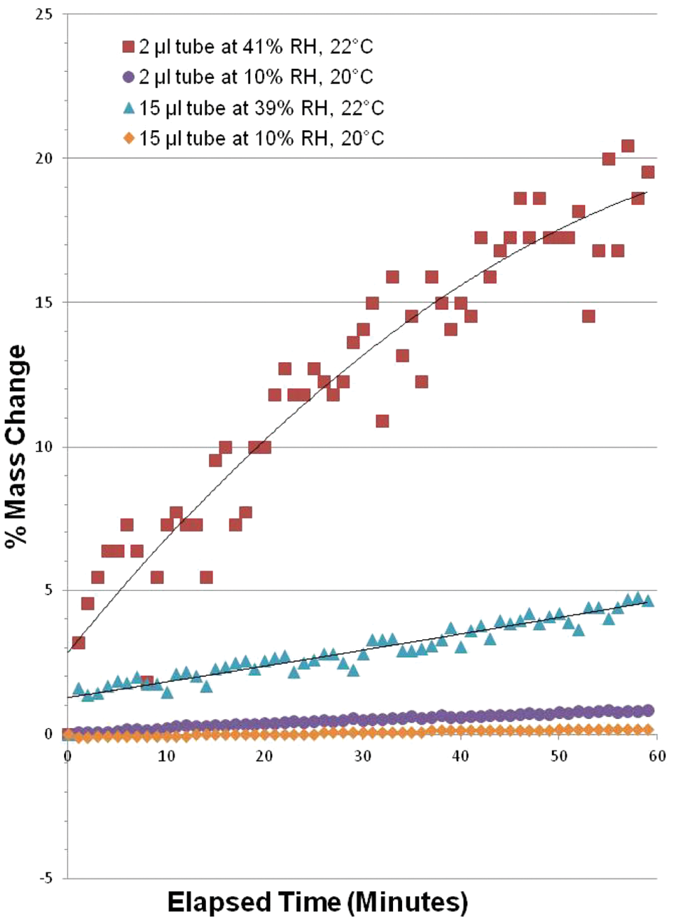
DMSO percent mass change with humidity conditions. Punch tubes from Remp STBR384 plates (Brooks Automation, Inc.) were individually filled with 2 µL and 15 µL neat DMSO on an analytical balance. Change in mass was recorded at 1-min intervals in both dry (10%) and ambient (39%–41%) relative humidity (RH) conditions.
With an opportunity to avoid moisture introduction into DMSO-solubilized compound solutions, frozen storage at minimally cold temperatures (−5 °C or −20 °C, Remp LSS dependent) could be ensured. Minimal moisture absorption was sought to reduce opportunities for compounds to degrade or precipitate from solution as described in earlier communications. Therefore, ALPS was specified to process all exposed compound solutions with relative humidity not to exceed 10%. To avoid the possibility of neat DMSO freezing (mp = 18 °C/64 °F), ALPS operating temperature was specified as 70 to 75 °F (21–24 °C).
Originally intended as one project, ALPS was split into separate automation integration and facilities renovations projects. Early design concepts called for apportionment of a large laboratory space for installation of a gasket-sealed acyclic glass enclosure. This enclosure would have isolated a dehumidified area for ALPS. This “room within a room” concept struggled to gain acceptance from both engineering and aesthetics viewpoints. For operator interaction, the enclosure would have required numerous access doors and windows, thus complicating an effective vapor barrier design from an engineering standpoint. Separate fire suppression equipment would also have been required. From a workflow approach, this “room within a room” concept would have logistically hindered other compound management activities, requiring obtrusive walk-around paths. Alternatively, at a later point in the design phase, a smaller laboratory became available for renovation that better suited ALPS size requirements. The new location obviated the initial separate enclosure concept for a functionally more appealing walk-in design that provided operators greater access to the automation equipment. In the context of a dry room paradigm, acrylic glass was specified only at relevant areas for the purpose of machine guarding. The 50 × 30-foot laboratory dry room was designed with vapor barriers in walls, floors, and overhead to seal in the controlled dehumidification ( Fig. 7 ). Laboratory renovations were designed by Stantec Consulting Services (Hauppauge, NY) and constructed by Whiting-Turner (New Haven, CT) using a dehumidification system manufactured by Munters (Amesbury, MA). The system was capable of maintaining 10% relative humidity, dissipating ALPS instrument heat loads, and exceeding fresh air exchange requirements. With efficiency and energy conservation in mind, the cooling and desiccant system was designed to cascade off existing building air handlers.
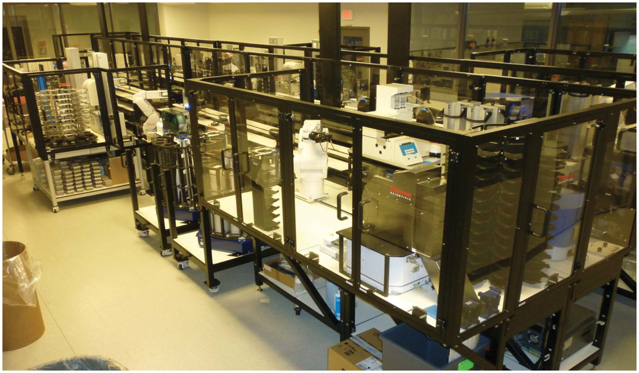
The Automated Liquids Processing System (ALPS) following site acceptance testing at Boehringer Ingelheim in Ridgefield, Connecticut. ALPS was installed following laboratory renovations to control relative humidity at ≤10% and room temperature at 70 to 75 °F. Machine guarding is shown surrounding F5 robots. Machine guarding was zone specific, allowing operators to open doors for maintenance at one F5 robot work envelope without emergency-stopping other active F5 robot work envelopes. Overall dimensions for ALPS were approximately 39 feet long by 17 feet wide.
Laboratory entrance doors were designed to be gasket sealed. With an arid environment, the generation of static electricity was a broad concern and, accordingly, a flooring system was specified that incorporated electrostatic dissipative tiles. The ALPS laboratory space was also shared by two smaller Freedom Evo 200 automation systems (Tecan US, Inc., Durham, NC). These systems, also requiring a 10% relative humidity environment, were purposed for creating solution master stocks from dry compounds in vials that, following transfer to compatible labware, were in turn used on ALPS.
Device Driver Development and System Build
The ALPS build was an endeavor by the integration vendor to assemble disparate hardware into integrated and coordinated components, while concurrently addressing major upgrades to its control software, Momentum 3.0. During hardware integration and Momentum 3.0 development, collaboration on properties and functions for each third-party instrument’s driver took place between the customer and vendor. The driver development goal was to provide the same functionality and access to third-party instruments under Momentum 3.0 control as when running in stand-alone mode. Most third-party instruments for ALPS were purchased directly by Thermo Scientific Laboratory Automation for delivery to its factory build site on behalf of Boehringer Ingelheim. As an exception to this purchasing plan, the Remp CSP384 tube sealer was previously acquired and already in production use. The Remp CSP384 tube sealer could not be delivered to the factory for integration due to its essential daily use, and budgetary concerns prevented the purchase of an additional unit. Contingencies were made for Thermo Scientific Laboratory Automation software developers to have access to the Remp CSP384 tube sealer during a site visit to write its instrument driver.
Midway through the build, a visit to the factory facilitated discovery of issues not easily revealed during project web conferences and teleconferences. Conferences were held monthly and then weekly as the factory acceptance test date approached.
Factory and Site Acceptance
The system specification called for three major process flowcharts to be programmed and executed during both factory and site acceptance testing (FAT/SAT). All three tests were required to execute on both ALPS subsystems. Each hardware and software requirement in the specification document was described with detailed test protocols for confirmation during FAT/SAT (described below). Both FAT and SAT took 5 days to perform.
FAT/SAT Test 1: A one-to-many plate replication scheme in which 70 source compound plates were required to generate 70 intermediate dilution plates and 1120 replicate plates. This included labeling, sealing, and collating all plates in less than 20 h.
FAT/SAT Test 2: A concentration-response plus replication scheme, requiring 20 source compound plates, each of which generated 10 dilution plates. Each dilution plate spawned 5 replicate plates for a total of 1200 plates produced in less than 20 h, including barcode labeling, sealing, and output collating.
FAT/SAT Test 3: A 96-to-384 reformatting scheme, starting with 120 source compound deep-well plates and generating 600 × 384 punch tube plates, 240 × 96 punch tube plates, and 60 × 384-well plates with barcode labeling and sealing in 15 h.
Project Milestones
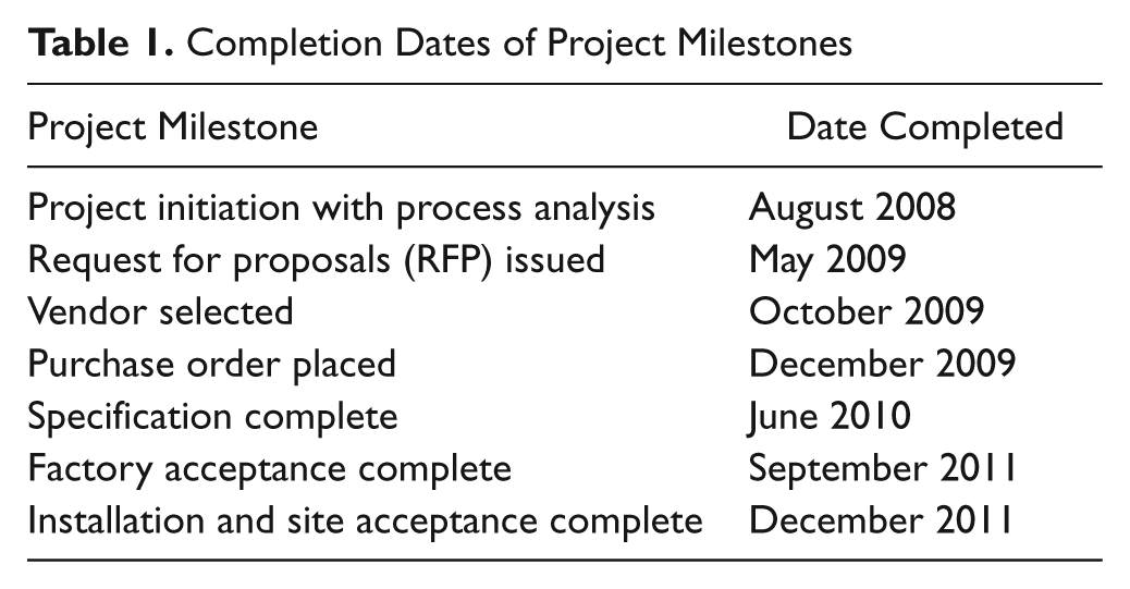
At the satisfactory completion of milestone goals for system integration, a percentage of the capital expense for the project was released. A capital expense of 10% was held in reserve until completion of noncritical exceptions that could only be completed following SAT. Exceptions were completely resolved 3 weeks after SAT. A project timetable is described in Table 1 .
Completion Dates of Project Milestones
Conclusion
Previous noncontiguous operations consumed significant amounts of full-time employee (FTE) time in solution-based operations across sample management. For example, preparation of thirty-five thousand 384-well single-use plates for primary HTS took one FTE approximately 7 months to complete. In contrast, with ALPS, one-third FTE can complete 49 000 HTS plates in approximately 1 month by using both subsystems and incorporating overnight runs. As such, ALPS has fulfilled its objective of significantly improving productivity in solution-based plate-handling operations. Possessing a plate generation capacity of 2800 plates, ALPS can efficiently prepare compound solutions around the clock. With each subsystem having the capacity to unseal, pierce, label, transfer, mix, seal, and collate at a rate of 60 s or less for nearly 24 h, ALPS was designed with a forward-thinking mind-set to keep pace with the growing needs of compound management.
The controlled relative humidity environment minimized risk of compound precipitation and avoided depression of melting points during long-term cold storage of DMSO solutions. Following acceptance testing, ALPS was turned over without delay to operators for production use. In the initial 3 months, approximately 12 000 plates have been created for HTS screening sets, concentration-response sets, compound validation sets, and 96- to 384-well conversion projects. Smaller ALPS tasks, such as barcode relabeling projects and control plate generation, have emerged due to the ability for operators to quickly develop new flowchart processes.
Footnotes
Acknowledgements
The authors gratefully acknowledge and thank the following colleagues for their support in this project: Thermo Scientific Laboratory Automation, Elena Bondar, Bryan Favara, Michael Riff, Michael Garneau, Fernando Cano, Jay Kay, and Paul Ainsworth for system integration, installation, and testing; Alain Richard, Rui Fernandes, Evelyne Ploquin, Pete Whelan, and Keith Corkum for software development and testing; and Rob Dunn-Dufault, Hansjoerg Haas, and Grace Mangialardi for sales and training support. From Boehringer-Ingelheim, Richard Nelson for sponsoring the project; Charles Mastroni for purchasing support; Dan Bushey, John McLoughlin, and Nancy Lounsbury for information systems support; Ed Kinsman, Mostafa Elmorsi, Thomas Sinno, and David Ambrose for design and construction of the dry room laboratory; and Bill Galdenzi, David Redalieu, and Mary McConnell-Meachen for health and safety support.
Declaration of Conflicting Interests
The authors declared no potential conflicts of interest with respect to the research, authorship, and/or publication of this article.
Funding
The authors received no financial support for the research, authorship, and/or publication of this article.