
Abstract
There is an increasing demand for novel high-throughput screening (HTS) technologies in the pharmaceutical and biotechnological industries. The robotic sample-handling techniques currently used in these industries, although fast, are still limited to operating in multiwell plates with the sample volumes per reaction in the microliter regime. Digital microfluidics offers an alternative for reduction in sample volume consumption for HTS but lacks a reliable technique for transporting a large number of samples to the microfluidic device. In this report, we develop a technique for serial delivery of sample arrays to a microfluidic device from multiwell plates, through a single sample inlet. Under this approach, a serial array of sample plugs, separated by an immiscible carrier fluid, is loaded into a capillary and delivered to a microfluidic device. Similar approaches have been attempted in the past, however, either with a slower sample loading device such as a syringe pump or vacuum-based sample loading with limited driving pressure. We demonstrated the application of our positive-pressure–based serial sample loading (SSL) system to load a series of sample plugs into a capillary. The adaptability of the SSL system to generate sample plugs with a variety of volumes in a predictable manner was also demonstrated.
High-throughput sample processing is a critical requirement for a large number of industries. Some examples include the agricultural, pharmaceutical, and biotechnological industries. 1 As a result, there is a constant drive for innovation in sample-processing techniques, supporting these industries. One major breakthrough in this domain has been the application of various robotic sample-handling techniques to improve the speed of sample processing as well as to reduce the volume of reagents used per reaction. Although the robotic systems have become incredibly fast at sample-processing operations, they are typically limited to operating with standard multiwell (96-, 384-, and 1536-well) plates. As a result, the typical sample volume consumption is on the order of microliters per reaction for such systems. 1 Recent advances in the microfluidic domain show promise in overcoming this limitation of the robotic systems. Droplet-based microfluidic systems have been shown to be capable of performing biomolecular screening with sample volumes as low as picoliters. 2 –6 However, introducing a large number of samples on a miniature microfluidic device is difficult because it is impractical to have hundreds to thousands of sample inlets to a single microfluidic device. Furthermore, the tubing used for supplying the samples to such a microfluidic device would already consume orders of magnitude more sample than is required for the actual analysis on the microfluidic device. So there is a need for an efficient way to transport a large number of samples to a microfluidic device. Ideally, such a sample transport system would be flexible enough to supply a variable number of samples to a microfluidic device without any modifications in the transport system or the device.
The “plug-in cartridge” technique developed by the Whitesides group 7 provides an elegant solution to the problem of introducing a large number of reagents on a microfluidic device through a single inlet. Under this approach, a series of sample plugs are loaded into a capillary, with air bubbles present between sample plugs acting as spacers. This capillary is connected to a microfluidic device for serial delivery of these sample plugs. However, in this approach, the sample plugs are constantly in contact with the capillary inner surface, leading to the problem of cross-contamination between plugs. 7 Another modification of this approach developed by the Ismagilov group 8 uses an immiscible carrier fluid instead of an air bubble to act as a spacer between sample plugs. The carrier fluid in this approach preferentially wets the inner surface of the capillary, thus preventing direct contact between sample plugs and the capillary surface. As a result, the problem of cross-contamination between sample plugs is eliminated. The carrier fluids typically used for generating these sample plug arrays are fluorinated oils, which also reduce the problem of reagents leaking from sample plugs into the carrier fluid due to their low solubility for most reagents. 8
Although this approach is promising, the current techniques used under this approach for generating the sample plug cartridges have some issues that need to be resolved. The common technique of using a syringe pump for aspirating sample plugs from a sample well 9 –11 in a multiwell plate can be extremely slow. Another technique of using a vacuum for aspirating a sample plug can be much faster. 7 However, this technique can provide a maximum driving pressure of only 1 atm (~15 psi). As a result, the driving force may not be sufficient to load large numbers of sample plugs into a capillary because of the increasing fluidic resistance of the capillary with the introduction of sample plugs. Furthermore, both of these techniques require the free end of the capillary to be attached to either a syringe or a vacuum source, thus excluding the possibility of operating this sample loading system in sync with the operations on a downstream microfluidic device. This can be a major setback to throughput as the possibility of conducting assays in continuous flow manner on microfluidic devices, as has been demonstrated earlier, 12 is precluded.
To overcome these issues, we conceptualized and fabricated a sample plug loading system that uses positive pressure for loading sample plugs from an industry standard multiwell plate to a capillary. Figure 1 shows a schematic illustrating the working principle of this system. A critical component of this system is a capillary adapter, which acts as an interface between a capillary, to be used for holding the sample plug array, and a multiwell plate used for holding samples. As shown in the schematic, the capillary adapter can be sealed with a sample well on the multiwell plate, creating a temporary pressure chamber in the sample well. In this sealed mode, the capillary attached to the capillary adapter is immersed in the sample present in the well. The pressure input on the capillary adapter can then be used to apply pressure to the sample in the well for a controlled amount of time. As a result, a small plug of sample is pushed from the well into the capillary. The size of this plug can be controlled by varying the input pressure and the pressure application time. Repeating this process with multiple sample wells can be used to generate an array of sample plugs in the capillary. As is clear from Figure 1 , this whole sample plug loading process requires only one end of the capillary to be engaged, while the other end of the capillary is free to be interfaced with a downstream microfluidic device, where further operations can be carried out with the sample plug array.
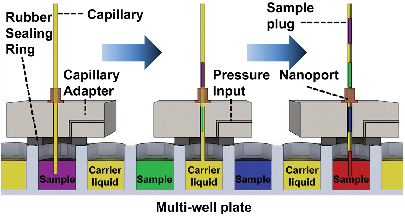
A schematic illustrating the working principle of the sample plug loading system. This positive-pressure–based sample loading system involves interfacing a capillary with a sample well through a capillary adapter. The capillary adapter can be used to seal a sample well from a multiwell plate, creating a temporary pressure chamber in the sample well. Application of pressure to this sealed sample well through the capillary adapter leads to introduction of a sample plug from the sample well into the capillary.
Figure 2 shows a detailed model of the capillary adapter we designed in the CAD software Solidworks (Solidworks Corp., Waltham, MA). The wider backside of the adapter with the three large holes is used to bolt the capillary adapter to a stable support. The narrower front side is the actual functioning head of the capillary adapter. The functioning head consists of three disc-shaped recesses on three sides (top, left, and right), which are used to seat three NanoPorts (Idex Health and Science, Oak Harbor, WA). The NanoPorts can be used to make a leak-free connection with different types of tubing. The NanoPort on the top side is used to attach the capillary to the capillary adapter. The NanoPort on the left side is used to attach the pressure supply line to the capillary adapter, whereas the NanoPort on the right side can be used to gauge pressure in the sample well, if required. All of these NanoPorts holding locations on the capillary adapter have holes drilled in the center and routed to the bottom of the capillary adapter, as shown in the bottom view ( Fig. 2 ). When in use, the capillary goes through the straight hole drilled from the top of the capillary adapter to the bottom side. The bottom side of the capillary adapter has a disc-shaped recess and a protruding circle. The disc-shaped recess holds a silicone sealing ring, which is used to temporarily seal the capillary adapter with a sample well on a 96-well plate. The protruding circle acts as a centering feature, which is used for centering the capillary adapter into a sample well.
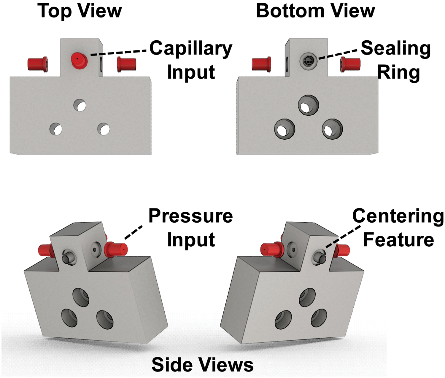
Different views of a CAD model of the capillary adapter actually used for fabrication of the capillary adapter. The wider backside of the adapter with the three large holes is used to bolt the capillary adapter to a stable support. The narrower front side is the actual functioning head of the capillary adapter.
Our assembled serial sample loading (SSL) platform is shown in Figure 3 . All the components of the SSL platform are attached to an aluminum breadboard for support. A vertical stainless-steel post bolted to the aluminum breadboard provides strong support structure for the capillary adapter. The capillary adapter is bolted to an angle bracket, which can slide on the post. This assembly allows us to manipulate the height of the capillary adapter from the aluminum base, as required. The capillary adapter is fixed at a suitable height to leave sufficient space for an assembly for XYZ motion of a 96-well plate below it. To control the cost of the pilot system, we chose to keep the motion of the 96-well plate in the XY plane manual by using simple rails. However, these rails can be easily replaced with a motorized XY stage for automated motion of the 96-well plate. Controlled motion of the 96-well plate in the Z dimension, however, is critical for providing a reproducible seal between the capillary adapter and a sample well. So the motion in the Z-dimension was motorized. Typical linear translation stages are ill-suited for this application because of the limitation on the load supported by these stages along the direction of travel. Hence, a motorized lab jack was used for automated motion of the 96-well plate in the Z dimension. Figure 3 also shows an electronic pressure controller, which can control the pressure applied to a sample well through the capillary adapter.
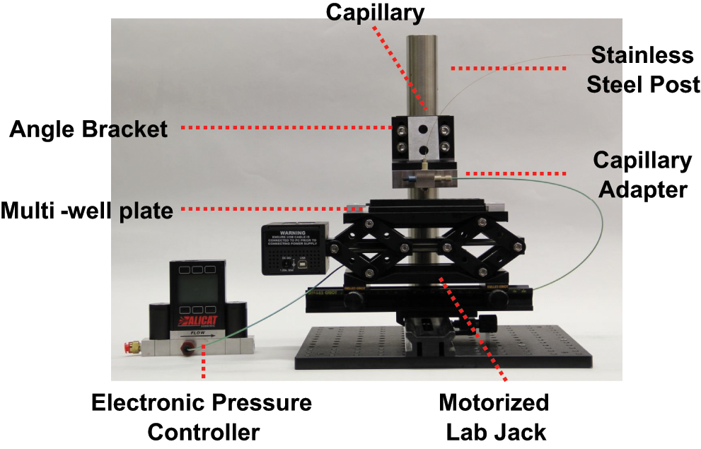
A photograph of the actual assembled serial sample loading (SSL) system. The SSL system features a custom-made capillary adapter to interface a capillary with the multiwell plate, a motorized lab jack for vertical motion of the multiwell plate, and an electronic pressure controller to control to pressure applied to a sample well for sample plug loading into the capillary.
Materials and Methods
The capillary adapter was designed in Solidworks (Solidworks Corp.) and then fabricated at the Physical Sciences Machine Shop at Johns Hopkins University. The capillary adapter was fabricated using stainless steel as substrate, to prevent corrosion due to contact with biological samples and buffers. All other structural components for the SSL system were purchased from Thorlabs (Newton, NJ). A motorized lab jack (L490MZ/M, Thorlabs) was purchased to use for computer-controlled vertical motion of the 96-well plate in the SSL system. The electronic pressure controller used with the SSL system was purchased from Alicat Scientific Inc. (Tucson, AZ). The pressure controller used is a dual-valve pressure controller (PCD-100PSIG-D-PCV03), which eliminates the need for bleed ports and relief valves typically required for pressure control in a closed volume. NanoPorts (N-124H, N-333 and N-125H Idex Health and Science) were bonded to the capillary adapter at the three ports according to the instructions provided by Idex. The sealing ring attached to the bottom of the capillary adapter was fabricated using a silicone septum (Corning, Corning, NY). The ring shape was punched out of the silicone septum using hole punches (3/8″ and 13/64″ hole diameter; McMaster). The capillary adapter was designed to be compatible with Costar 96-well plates (Corning). The motorized lab jack and the electronic pressure controller were interfaced with a computer through USB ports. Custom software written in LabVIEW (National Instruments, Austin, TX) allowed us to control the motion of the 96-well plate in the vertical direction, as well as the pressure applied to a sample well through the capillary adapter.
The sample loading experiments were conducted using Silica Capillary Tubing (Polymicro Technologies, Phoenix, AZ). The capillaries were treated with Aquapel (PPG Industries, Pittsburgh, PA) before an experiment to render the inner surface of the capillary hydrophobic. The samples used for most experiments were food dyes (Ateco, Glen Cove, NY), unless specified otherwise. The carrier fluid used for separating sample plugs from each other was a mixture of FC-3283 (3M, St. Paul, MN) and 1H,1H,2H,2H-perfluoro-1-octanol (Sigma-Aldrich, St. Louis, MO) in the ratio of 8:1 by volume. For these experiments, the Aquapel-treated capillary was completely filled with the carrier fluid first. Following this, a sample well on the 96-well plate was manually aligned with the capillary adapter. The LabVIEW software then raised the 96-well plate in the vertical direction, to seal the sample well with the capillary adapter. The same software was then used to apply the desired pressure profile to the sample well for the desired amount of time. Following this, the 96-well plate was lowered by the LabVIEW software. We then manually aligned another well containing the carrier fluid with the capillary adapter. The same sample plug loading steps were then used to load a carrier fluid plug into the capillary. This alternating sequence of sample and carrier fluid plug loading was repeated until the desired number of sample plugs was loaded into the capillary.
For the experiments that required sample plug volume estimation, we used a 1-m-long silica capillary with a 200 µm inner diameter. The sample used for these experiments was a single food dye. A series of 12 sample plugs separated by carrier fluid was loaded into the capillary using the steps described above. This capillary was then placed on the white background of a letter-sized sheet of paper and imaged using a digital single-lens reflex camera. The camera was placed such that the whole letter-sized paper was included in the camera’s field of view. The image was then imported in ImageJ 13 for plug volume estimation. Length scale was set in the image using the known length of the letter-sized sheet of paper. Following this, the length of each sample plug was measured by manually drawing a line marking the length of the plug in ImageJ. This measured length, along with the known cross-sectional area of the capillary, was then used to estimate the plug volume for each sample plug. The plug volume data from the last 10 sample plugs for each loading condition was then used for the data analysis.
Results
One of the first critical tests of our SSL platform was to determine its capability to provide significantly higher driving pressure than vacuum (~15 psi) for sample plug loading in a capillary. To conduct this test, we first attached a silicone sealing ring to the capillary adapter, as described in the Materials and Methods section. The NanoPorts for the capillary and pressure gauge on the capillary adapter were plugged using plugs (Idex Health and Science). The electronic pressure controller was connected to an input pressure supply of 95 psi from a nitrogen cylinder. A sample well on a Costar 96-well plate was then sealed with the capillary adapter using the SSL system. The LabVIEW software was then used to raise the pressure in the sealed sample well to different peak pressure values (10, 20, 30, 40, and 50 psi). Figure 4 shows a plot of the pressure in the sample well, sensed by the pressure controller, for these five different tests. The pressure plot for each test consists of three distinct regions: rising phase (the pressure in the sample well is raised from 0 to peak value during this phase), peak pressure phase (pressure in the sample well is maintained at peak value during this phase), and decline phase (pressure in the sample well is reduced from peak to 0 psi during this phase). The duration of each of these phases can be controlled using the LabVIEW software. All of these phases were fixed at a duration of 5 s each for the plots shown in Figure 4 . The pressure plots demonstrate that the pressure controller can easily maintain a peak pressure of 50 psi in the sealed sample well as commanded, thus proving that our SSL system can provide substantially higher driving pressures than a vacuum-based system for sample plug loading in a capillary. The pressure controller we used was factory calibrated to a maximum pressure of 50 psi. Hence, we could not test the SSL system for pressures higher than 50 psi. Furthermore, Figure 4 also demonstrates that the pressure controller can control the timing of the rising and peak pressure phases very precisely. The duration of the decline phase, however, being a passive process driven by the pressure difference between the sealed sample well and the atmosphere, depends to some extent on the peak pressure value.
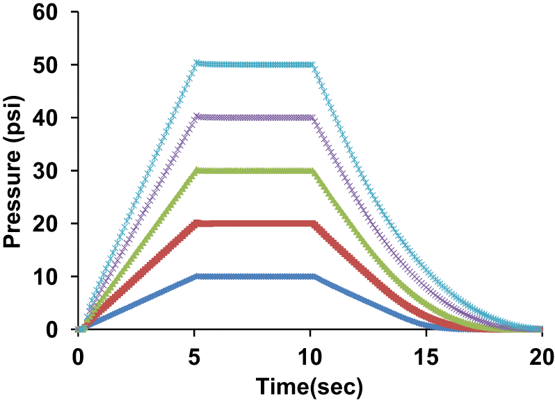
A plot of pressure variation in the sample well over time for different peak pressures (10, 20, 30, 40, and 50 psi) applied to the sample well. The pressure variation is sensed by the electronic pressure controller in the serial sample loading (SSL) system. Each individual plot shows three distinct phases of pressure application to the sample well: (1) rising phase (the pressure is raised from 0 to peak pressure during this phase), (2) peak pressure phase (pressure is maintained at its peak value during this phase), and (3) decline phase (the pressure is reduced from peak pressure to 0 during this phase). The duration of all of these phases was maintained constant at 5 s each for all the plots in the figure. The plots demonstrate precise timing and pressure control of the SSL system in the sample well. Furthermore, the plots also demonstrate that peak pressure of up to 50 psi could be easily maintained in the sample well.
We then tested the capability of the SSL system to load a series of sample plugs into a capillary. Initial testing was conducted using food dyes as samples for easy visibility. A silica capillary was loaded with alternate plugs of different food dyes and carrier fluid using the SSL system. Figure 5a shows a micrograph of the silica microcapillary with a few food dye sample plugs. The micrograph shows excellent uniformity of plugs, the ability of the SSL system to keep sample plugs separate from each other, as well as the capability to load sample plugs without breakup into the capillary. We then tested the sample plug loading scheme with a biologically relevant sample in the form of a PicoGreen (Life Technologies, Carlsbad, CA)–stained Lambda DNA (Promega, Madison, WI) sample. The Lambda DNA was present at a concentration of 2 µg/mL concentration in the sample. Biological samples provide additional challenge to the sample plug loading process because of the lack of any visual feedback during sample plug loading. Food dyes are easily visible, and their plug uniformity can be easily discerned during the loading process. However, with most biological samples being transparent, it is difficult to differentiate them from the transparent carrier fluid. The variation in plug size is solely dependent on the repeatability of the SSL system. We thus loaded these Lambda DNA sample plugs into a silica capillary essentially blindly and then obtained a fluorescence image ( Fig. 5b ) of the silica capillary using a Typhoon 9410 Variable Mode Imager (GE Healthcare, Waukesha, WI). The fluorescent Lambda DNA plugs can be clearly seen over the dark background of the interspersed carrier fluid plugs. Excellent uniformity of plug loading, despite lack of visual feedback, is also clearly evident from this image. The ultimate purpose of the SSL system is delivery of a large array of sample plugs to a microfluidic device for further processing. So, as a proof of principle, we also demonstrated interfacing of a capillary with a simple microfluidic device ( Fig. 5c ). A series of sample plugs made from food dye using the SSL system was then delivered from the capillary to the microfluidic device. Excellent transition of sample plugs from the capillary to the microfluidic device without breakup can be clearly seen from the image in Figure 5c .
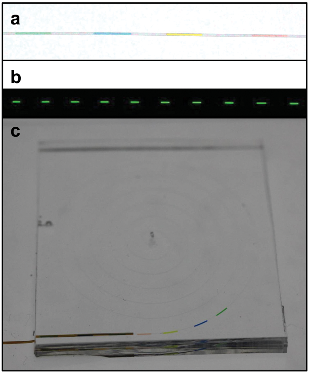
Micrographs demonstrating the capability of the serial sample loading (SSL) system to load uniform sample plugs into a capillary. (
We then conducted more rigorous testing of the SSL platform to determine its capability to maintain sample plug uniformity as well as control the sample plug size as desired. To conduct these experiments, we loaded a series of 12 sample plugs made of the same food dye into a 1-m-long silica capillary for each set of sample plug loading conditions, as described in the Materials and Methods section. The sample plug volume estimated from the last 10 sample plugs was used to estimate the mean and standard deviation of the plug volume for each loading condition. These values were then used for the plots shown in Figures 6 and 7 .
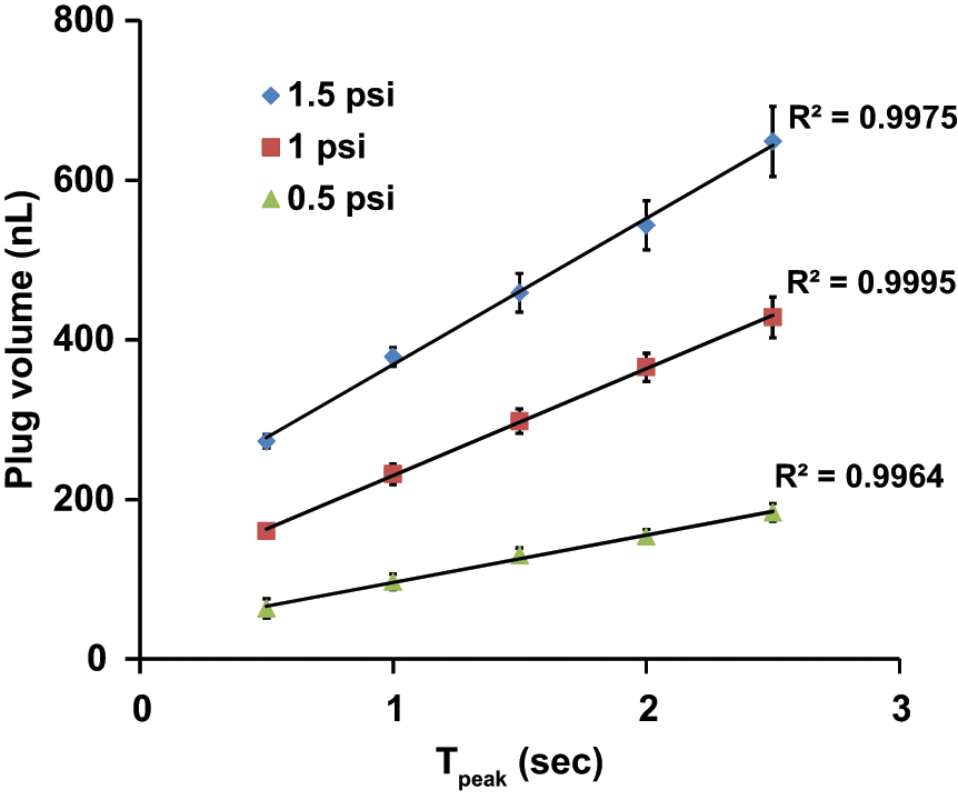
Plots showing the linear relationship between sample plug volume and the duration of the peak pressure phase (Tpeak) for three different fixed values of peak pressure (Ppeak: 0.5, 1, and 1.5 psi) applied. Each data point shows the mean and standard deviation of the volume of 10 sample plugs generated for each sample plug loading condition.
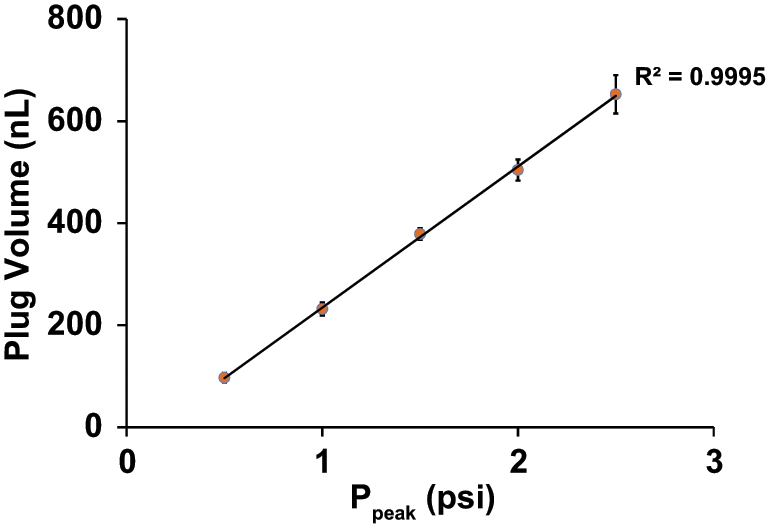
Plot showing the linear relationship between the sample plug volume and the peak pressure (Ppeak) applied for a fixed duration of the peak pressure phase (Tpeak: 1 s). Each data point shows the mean and standard deviation of the volume of 10 sample plugs generated for each sample plug loading condition.
The sample plug volume depends on a few factors: (1) peak pressure (Ppeak) applied, (2) duration of the rising and decline phases of pressure application, and (3) the duration (Tpeak) of the peak pressure phase. All of these parameters can be precisely controlled in the SSL system with our LabVIEW software. We decided to vary the intuitive factors such as Ppeak and Tpeak to control the sample plug volume. Initially, we held Ppeak constant and varied Tpeak to estimate the sample plug volume generated for different Tpeak values. This experiment had two objectives: first, to estimate the variation in plug volume for a fixed set of loading conditions, and second, to estimate the relationship between plug volume and Tpeak for a fixed value of Ppeak. Figure 6 shows a plot of sample plug volume versus Tpeak for three different values of Ppeak (0.5, 1, and 1.5 psi). The linear relation between plug volume and Tpeak for each individual Ppeak value demonstrates the capability of the SSL system to precisely control the plug volume in a predictable manner, through the variation of the duration of the peak pressure phase. Furthermore, the plug size variation indicated by the error bars is fairly low, with a maximum coefficient of variation of approximately 7% for all but the two smallest plug volumes generated, where we were approaching the lower limit of the operation of the electronic pressure controller. We expect the system performance, in terms of plug volume variability, to improve as the motion of the 96-well plate is automated in the horizontal plane too, as the overlap of the sample well wall with the sealing ring of the capillary adapter can be reproduced across the area of the 96-well plate, providing a reproducible seal for every single sample plug loading step.
Varying Tpeak to control plug volume can be beneficial for smaller plug volumes. However, as the plug volume increases, Tpeak can quickly increase, reducing the speed at which sample plugs can be loaded in a capillary. For larger plug volumes, it would be beneficial to raise the peak pressure to achieve larger plug volume in the same amount of time. Figure 7 shows a plot of the sample plug volume versus Ppeak for a fixed value of Tpeak (1 s). This plot shows another linear relationship between sample plug volume and Ppeak, providing an alternative predictable way to vary the sample plug volume through variation of the peak pressure applied to the sample well. The value of Ppeak here is limited only by the pressure at which the seal between the sample well and the capillary adapter breaks down. This result thus illustrates a limitation of applying a vacuum to load sample plugs in a capillary, which can be overcome with the use of the SSL system. Although the vacuum level can be controlled with a regulator, the driving pressure cannot be greater than 1 atm (~15 psi), limiting the speed at which large sample plugs can be loaded in a capillary.
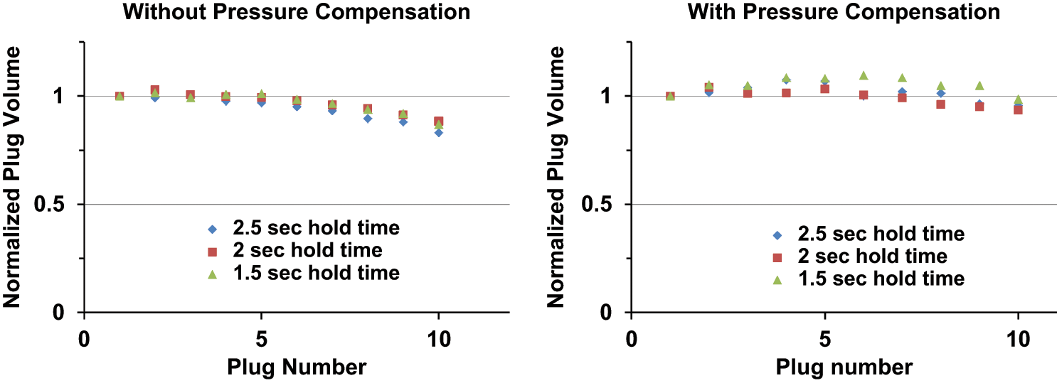
One limitation of the SSL system is its dependence on the fluidic resistance of the capillary for maintaining the uniformity of sample plug volume for the same sample plug loading conditions. However, as more and more sample plugs are loaded into the capillary, the fluidic resistance of the capillary increases, gradually reducing the sample plug volume over the course of loading of sample plugs. This effect is illustrated in Figure 8a . In this figure, the sample plug volume data are normalized by the plug volume of the first sample plug generated for each loading condition. The normalized sample plug volume is then plotted against the sample plug number in the loading sequence. As seen from the plot, for three independent loading conditions (Ppeak: 1 psi, Tpeak: 1.5, 2, and 2.5 s), we observe a consistent gradual reduction in the sample plug volume as the number of sample plugs in the capillary increases.
(
This problem can be avoided through pressure compensation for the changing fluidic resistance of the capillary. We observed the sample plug volume reduce by approximately 15% for the 10th sample plug loaded into a capillary for all of the 3 conditions shown in Figure 8a . So we did a simple linear peak pressure (Ppeak) increase for each sample plug in the loading sequence to compensate for the 17% (1/0.85) increase in the fluidic resistance over the course of loading 10 sample plugs in the capillary. The normalized sample plug volumes for this modified loading scheme with the same starting point as the three conditions shown in Figure 8a are plotted in Figure 8b . These plots demonstrate that a simple compensation scheme can avoid gradual reduction in sample plug volume with increasing number of sample plugs, further improving the sample plug uniformity of the SSL system.
In the future versions of the SSL system, the compensation scheme can be further improved by devising a mathematical model of the changing fluidic resistance in the capillary and incorporating it in the LabVIEW software, to automatically compensate for the changing fluidic resistance by varying the peak pressure (Ppeak) applied to the sample well for each consecutive sample plug being loaded into the capillary. Alternatively, an imaging-based technique can be used to detect the appearance of the edge between a sample plug and the carrier fluid at a particular distance from the end of capillary immersed in the sample solution, to provide feedback for computer control of the pressure controller. This approach can enable very accurate metering of sample plug volume for each sample plug despite changing fluidic resistance in the capillary.
Discussion
In conclusion, we have devised a new technique for serial delivery of a large number of samples to a microfluidic device, directly from a standard multiwell plate. Our SSL system differs from similar techniques developed by other research groups in the past, in the application of positive pressure as a driving force for the loading of a series of sample plugs into a capillary for direct delivery to a microfluidic device. The SSL system can be used for rapid sample plug loading into a capillary with the only rate-limiting step being movement of the multiwell plate, to load samples from different sample wells. We demonstrated the functioning of the SSL system as well as its capability to control precisely the sample plug volume. Because the SSL system engages only one end of the capillary in sample plug loading, it can be directly interfaced with a downstream microfluidic device for its operation in synchronization with the microfluidic device. In its current form, the SSL system was designed for loading sample plugs into a single capillary. However, the design can be easily extrapolated for simultaneous loading of sample plugs in multiple capillaries from a row of sample wells. We expect the SSL system to be instrumental in further improvement in the throughput of droplet-based microfluidic devices in future.
Footnotes
Acknowledgements
We would like to thank Dong Jin Shin for his help with writing the LabVIEW software for controlling the SSL system. We would also like to thank Ms. Nupura Bhise for providing us with some Costar 96-well plates for initial testing of the SSL system.
Declaration of Conflicting Interests
The authors declared no potential conflicts of interest with respect to the research, authorship, and/or publication of this article.
Funding
The authors disclosed receipt of the following financial support for the research, authorship, and/or publication of this article: We also thank the funding support from DARPA (Micro/Nano Fluidics Fundamentals Focus (MF3) Center), Pioneer Hi-Bred International, Inc., and NIH (R01CA155305, U54CA151838).
References
Supplementary Material
Please find the following supplemental material available below.
For Open Access articles published under a Creative Commons License, all supplemental material carries the same license as the article it is associated with.
For non-Open Access articles published, all supplemental material carries a non-exclusive license, and permission requests for re-use of supplemental material or any part of supplemental material shall be sent directly to the copyright owner as specified in the copyright notice associated with the article.