
Abstract
High-content screening (HCS) is becoming an accepted platform in academic and industry screening labs and does require slightly different logistics for execution. To automate our stand-alone HCS microscopes, namely, an alpha IN Cell Analyzer 3000 (INCA3000), originally a Praelux unit hooked to a Hudson Plate Crane with a maximum capacity of 50 plates per run, and the IN Cell Analyzer 2000 (INCA2000), in which up to 320 plates could be fed per run using the Thermo Fisher Scientific Orbitor, we opted for a 4 m linear track system harboring both microscopes, plate washer, bulk dispensers, and a high-capacity incubator allowing us to perform both live and fixed cell-based assays while accessing both microscopes on deck. Considerations in design were given to the integration of the alpha INCA3000, a new gripper concept to access the onboard nest, and peripheral locations on deck to ensure a self-reliant system capable of achieving higher throughput. The resulting system, referred to as Hestia, has been fully operational since the new year, has an onboard capacity of 504 plates, and harbors the only fully automated alpha INCA3000 unit in the world.
Introduction
High-content screening (HCS) is becoming an acceptable platform in academic and industry screening labs and is viewed by many as an integral part of the overall drug discovery process. 1 –6 The associated requirements of data acquisition, management, and storage for HCS prompted many groups performing large-scale HCS campaigns to implement different strategies for smooth operations, screening data management, and data storage/retrieval. 5 –11 The use of automated microscopy for image acquisition together with the availability of sophisticated image analysis software, allowing in many cases on-the-fly image analysis involving multiparametric algorithms, have substantially increased the desired throughput, making it in some cases the technology of choice to study complex biological questions. 12 –14
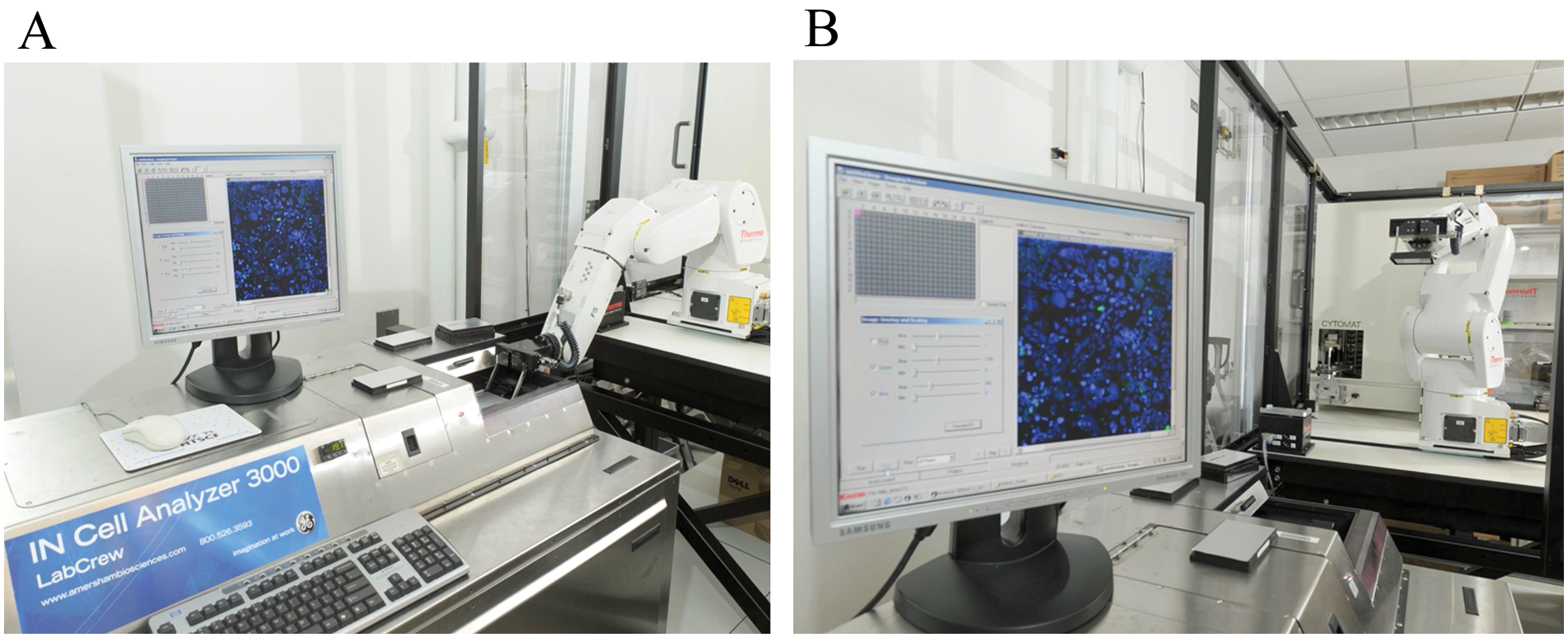
Our lab was equipped with one fully integrated IN Cell Analyzer 1000 (INCA1000) on a 6 m linear track platform referred to as Xanthus and two stand-alone automated microscopes, namely, an alpha IN Cell Analyzer 3000 (INCA3000) originally produced by Praelux ( Fig. 1A ) and an IN Cell Analyzer 2000 (INCA2000), a production unit purchased from GE Healthcare ( Fig. 1B ). The alpha unit was initially automated by hooking it to a Plate Crane (Hudson Robotics, Springfield, NJ) through a serial communication port with hard-coded scripting, allowing a limited plate-feeding capacity of 50 plates per run. The INCA2000, on the other hand, was partially automated by us through a hookup to an Orbitor RS Microplate Mover (Thermo Fisher Scientific, Waltham, MA) using dedicated driver software developed by Thermo Fisher Scientific and allowing a plate-feeding capacity of 320 plates per run. Both stand-alone units did not allow us to perform live cell-based assays in single read time nor in kinetic mode (multiple reads over a time course), thus limiting the repertoire of high-content assays offered as a service by the lab. Faced with performing only fixed cell-based assays with limited throughput for both chemical and RNAi screening efforts, we searched for a simple, reliable, and cost-effective automation solution allowing us to integrate both stand-alone units onto one robotic platform dedicated to our HCS efforts with room to grow and potentially add a third INCA2000 unit and to be able to perform live fully automated cell-based screens in dual modes.
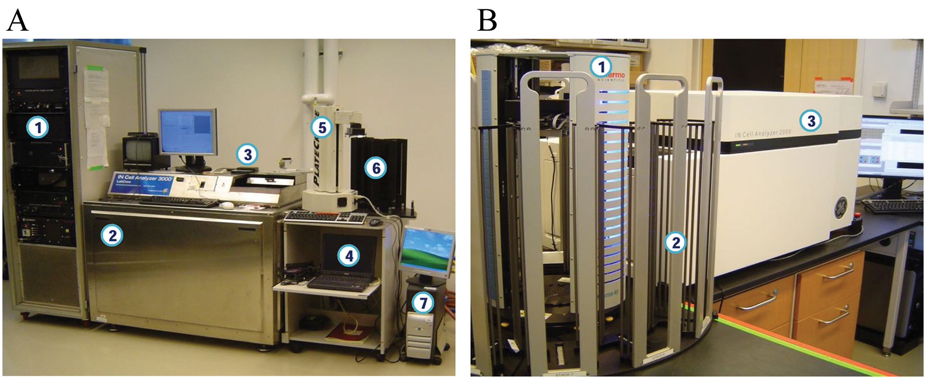
Automated microscopes. (
Several automation strategies were considered for this project, but in view of the inherent building code challenges, space limitation, and that the system build must be around the alpha INCA3000 unit, we opted for a linear track system on a 4 m table using the CRS F5 robotic arm to maximize all possible nest access and retrieval scenarios. The system layout design underwent several attempts to allow for both robotic arm maneuverability and, more importantly, engineer access for instrument servicing and maintenance. The fixed position of the alpha INCA3000 unit, its initialization, and subsequent operation procedures called for a smart solution for both instrument nest and flat-field reference plate access through the dynamic scheduler Momentum (version 2.0.1) and a novel design for deeper gripper fingers reaching both nests. In this report, we describe the various stages of the project leading to the final robotic platform referred to as “Hestia.”
Materials and Methods
Dedicated Laboratory Space
The laboratory space is located on the 19th floor of the Zuckerman Research Center building at Memorial Sloan-Kettering Cancer Center (MSKCC), New York, New York. The center was built according to the 1968 New York City building code with a D-2 occupancy class. 15 The allocated room for the HCS platform was limited to 428 square feet, and the floor’s maximum weight load could not exceed 60 kilograms per square footage. The prerequisite of the room was to maintain a steady environmental condition of the ambient temperature, fluctuating between 20 °C and 25 °C and free of airborne contaminants. The laboratory space needed to be prepped in advance with CO2 gas, compressed air, and electrical outlets to power the system. 16
Current HCS Setup
Automated INCA2000
The INCA2000 is a wide-field automated epifluorescence microscope equipped with a large-chip CCD camera (2048 × 2048 pixels) allowing for whole-well imaging. 7 The instrument dimensions are 654 mm × 1140 mm × 605 mm (depth × width × height) with a weight of 50 kg. The INCA2000 operating software (build version 3.0.0.43) runs on a Windows XP operating system. The operating software is equipped with a built-in driver compatible with the majority of integrations. The setup for the INCA2000 involves an Orbitor surrounded by nine stacks, eight out-stacks and one in-stack; it has a capacity of 40 unlidded 384-well microtiter plates per stack; and it has an onboard MS-3 (Microscan, Renton, WA) compact laser barcode scanner to capture the 32-character barcode for each sample plate. This setup was under the control of a Momentum 2.0.1 dynamic scheduler, allowing us to run one or multiple protocols. Using the system with multiple protocols requires each protocol to have a dedicated out-stack(s) and a dedicated in-stack(s), limiting the number stacks available. The maximum capacity of the INCA2000/Orbitor setup consisted of 320 sample plates per run.
Automated INCA3000
The alpha INCA3000 unit is an automated laser scanning confocal microscope. The operating software, Raven–IN Cell Analysis System (version 1.0), runs on a Windows 2000 operating system. The INCA3000 contains two solid laser light sources (argon and helium/neon) with three highly sensitive onboard 12-bit CCD cameras. The cameras operate simultaneously in the following ranges: blue, 430 to 495 nm; green, 505 to 595 nm; and red, 605 to 760 nm. The dimensions of the INCA3000 are 800 mm × 1128 mm × 1130 mm (depth × width × height), weighing 550 kg. Part of the INCA3000 instrument system, a control tower resides alongside the INCA3000, housing the INCA3000 PC/stepper motor power/electronics interface/temperature controller/one UPS/laser power source interface. The dimensions of the tower are 900 mm × 600 mm × 2020 mm (depth × width × height), weighing 250 kg. The INCA3000 was hooked to a Plate Crane, controlled by a laptop, and connected through a serial communication port with hard-coded scripting. The Plate Crane was surrounded with four stacks, two out-stacks and two in-stacks, and the maximum operational capacity was 25 plates per stack.
To maintain the lasers cooled at an operating temperature of 20 °C, a dedicated water cooling system was implemented ( Fig. 2 ); it comprises two liquid heat exchangers connected to a water tower located on the rooftop of the Zuckerman Research Center building. The first liquid heat exchanger located near the INCA3000 cools the lasers and maintains the preset temperature of 20 °C through an OTI-5WSS (Opti Temp Inc., Traverse City, MI) equipped with a 10 L liquid reservoir capacity, circulating the water in a closed loop. 17 The heat is then exchanged through a second loop from the OTI-5WSS to a Haskris R1000 (Haskris, Elk Grove Village, IL) industrial-size liquid heat exchanger system, located outside the laboratory room. The Haskris R1000 is a refrigerated water-recirculating system using an R22 refrigerant, cooling the water from the OTI-5WSS heat exchanger in a 114 L water reservoir to a temperature range of 12 °C to 15 °C. 18 The heat exchanged is transferred, via a thermal transfer, to a cooling condenser water loop connected to the in-house water tower. Water towers are an established method of cooling condenser water loops, in our case from the Haskris R1000. The condenser water flows directly over the heat transfer surface of the cooling tower. As the air is circulated over the coils, a small portion of the recirculation water is evaporated into the atmosphere, while the cooled water is returned to the Haskris liquid heat exchanger. 19 Maintaining an operating level for the R1000 and OTI-5WSS reservoirs requires checking the water level and replenishing on a monthly schedule.
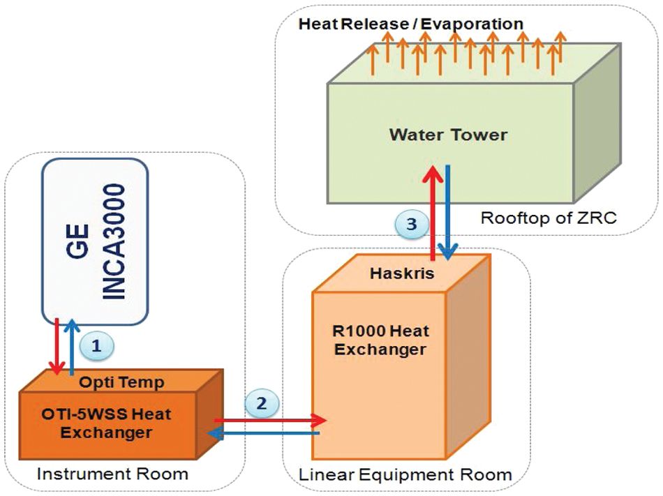
Cooling of alpha IN Cell Analyzer 3000 lasers. 1, Heat exchange loop between two laser light sources (argon and helium/neon) and OTI-5WSS. 2, Heat exchange loop between OTI-5WSS and R1000 heat exchanger (located outside of laboratory room). 3, Heat exchange loop between R1000 and water tower (located on the rooftop of Zuckerman Research Center).
The INCA3000 requires two operations to be performed for each run: The first operation requires alignment/calibration, and the second operation calls for a flat-field correction. Alignment/calibration is a series of checks performed by the instrument to ensure the laser power, camera temperature, mirrors, and shutters are all in working order. This operation needs to be conducted at startup and every 8 h thereafter. The software will not initialize until the operation is successfully completed. If an automated run exceeds 8 h, the system will continue until all plates are completely scanned; however, immediately afterward, the instrument will require the alignment/calibration step. The second operation required by the INCA3000 is a flat-field correction that needs to take place every three sample plates during the course of an automated run. The flat-field correction is done to correct for varying intensity of light on a sample. Because of the intensity of the laser beam that is bell shaped, emitting light is different in intensity between the edge and the middle beam, resulting in an image appearing darker on the left and right sides of the well and lighter down the center. The flat-field well contains a homogeneous solution of fluorescing liquid and is the designated flat-field well to be used. Because of the plate-molding process, we have chosen H4 as the flat-field well location; the optical quality is better away from the corner wells. The flat-field plate is also referred to as an auxplate, and reading the one well on the auxplate with the necessary corrections by the INCA3000 takes 115 s.
Results and Discussion
Design and Concept Reliance
Room design
The laboratory space assigned for the new robotic platform ( Fig. 3A ) was partially occupied by the INCA3000, an OTI-5WSS heat exchanger, the INCA3000 controller tower, a sink equipped with an eyewash station, essential workbench space, and several shelves. The laboratory space is also home to three large automated Biophile freezers, housing our compound libraries. Consideration was given to the Biophiles location in the room; in the event of an emergency, accessing the Biophiles would be crucial to retrieve sample plates.
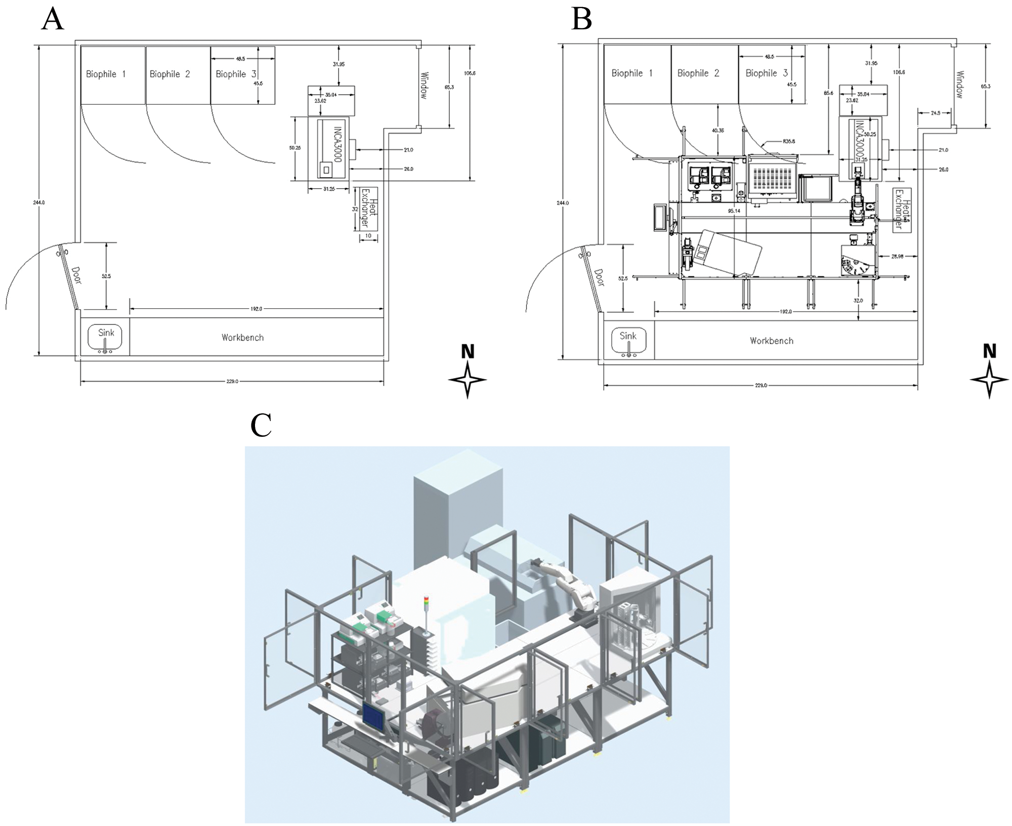
Laboratory space assigned. (
The HCS platform location is dictated by the INCA3000’s minimal maneuverability radius due to its weight, side-by-side dependency on the control tower, and close proximity to the OTI-5WSS heat exchanger. Precise measurements were made and defined to set safe passing clearance on the north, south, and west sides of the robotic platform. The east side of the platform was blocked by the OTI-5WSS heat exchanger, positioned behind the INCA3000. Because of the obstruction of the heat exchanger, the MSKCC safety department downgraded the laboratory room; however, the laboratory space remains compliant with the occupancy requirements of the New York City building code. The lab space was originally classified as a working lab, allowing scientists to occupy the laboratory space on a full-time basis with a permanent desk. The lab was downgraded to an instrument room, allowing scientists to work in the laboratory space without occupying it with a full-time desk. The space was prepped prior to the system installation with house CO2 gas medical grade at a purity of 99.5% supplied at 12 psi through 6 mm pneumatic tubing. The compressed house air is filtered and supplied at 95 psi through 10 mm pneumatic tubing. Electrical power was set to distribute at 110 VAC using four circuits at 20 amps each with a Nema 5-20R T-slot receptacle.
System design
The HCS platform was built around the INCA3000 and its location. It is a 4 m linear track ( Fig. 3B , C ) with an F5 articulated robotic arm along with various peripherals ( Table 1 ). Opting for a linear track allowed flexibility in the instrument layout and additional room to grow for the next generation of high-content technology.
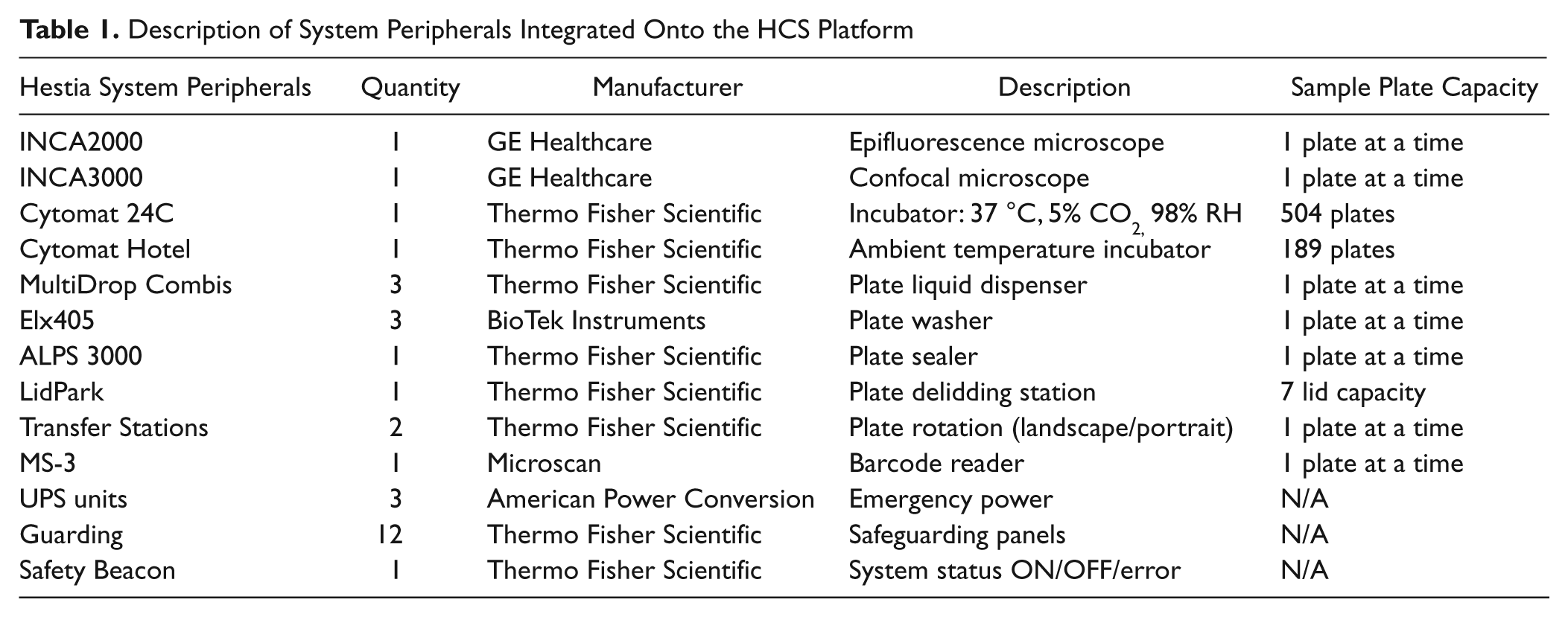
Description of System Peripherals Integrated Onto the HCS Platform
From conception to completion of the project, it took a little more than 3 years for the integrated HCS platform to be fully operational. Customizing the INCA3000 automation driver took about 1 year to develop, its communication tested virtually, and its overall ability to initialize the system through the newly designed and coded driver software. The original integration called for a communication between the INCA3000 unit and the Plate Crane to be hard coded within the script, thus creating an exclusive communication not amenable to sharing. The concept and design phase lasted 9 mo and 3 mo, respectively, to have all peripherals ordered and the system assembled. Upon completion, a factory acceptance test, without the INCA2000 and INCA3000, was performed in Canada, passing all the tests. A site acceptance test (SAT) was performed at our labs in New York, using the fully integrated HCS microscopes, passing all the tests once the system was fully installed. The SAT comprised testing every peripheral nest location to ensure the sample plate placement was correct and the data from the microscopes were parsed as specified.
Several supporting instruments were considered for the platform and compared based on reliability, cost, footprint, and service support. The instruments chosen ( Table 1 ) were purchased to facilitate several processes. A high-capacity incubator Cytomat 24C (Thermo Fisher Scientific), set at 37 °C, 5% CO2, and 98% humidity, and a Cytomat Hotel (Thermo Fisher Scientific) ambient temperature incubator are used for sample plate incubation and storage, varying on the onboard assay conditions. The fixing and staining process performed on deck is done by using three MultiDrop Combis (Thermo Fisher Scientific) with three ELx405 Washers (BioTek Instruments, Winooski, WI) and an ABgene3000 (Thermo Fisher Scientific), sealing the sample plates. Individual sample plates are tracked with a MS-3 compact laser barcode scanner capturing the 32-character (Code 128) barcode, consisting of a unique alphanumeric time stamp generated by our internal database. The shadow instruments that are crucial for our automated system consist of a LidPark (Thermo Fisher Scientific) with seven independent delidding nests and two regrip stations. One regrip station is dedicated for all on-deck peripherals depending on their nest layout, portrait or landscape orientation, rotating the plate’s 90° orientations, respectively. The second regrip station is solely dedicated to the INCA3000 unit, rotating the sample plates 180° to ensure that the A1 position in the assay plate is located on the top-left corner of the nest stage.
To achieve a self-reliant system capable of operating at maximum throughput, potential instrument bottlenecks were identified during the concept and design phase. Instruments that are step dependent of each other were placed within the same region to minimize robot travel time. Part of the system design called for clearance to be allocated for the INCA3000 and INCA2000. Part of the service requirements for the INCA3000 is to allow clearance to the front and right-side panels for accessibility. This is necessary to allow the service engineer to remove the panels and access the intricate interworkings of the microscope. The INCA2000 needs to have the front, back, and top panels accessed to perform the yearly preventive maintenance or any other service-related issues.
System communication
Communication of the system with most peripheral devices is done through a 16-port RS-232 serial communication expander RocketPort (Comtrol Corporation, New Brighton, MN). The SYS-IO physically resides on an expansion card in the automation computer. The automation computer relays digital signals to one or more ports on each peripheral; a system input-output or SYS-IO device communicates with one or more peripherals. Each of the peripherals that is communicating via the RS-232 RocketPort is assigned a COM port number; the properties of each peripheral are defined in Lab Creator, which is part of the dynamic scheduler package.
The handshake initialization between the INCA2000 and the automated system is done via an ethernet cable by configuring the TCP/IP addresses of both the INCA2000 computer and the automation computer. The communication route is achieved via a private local network that is part of the system, controlled by a router. The data from the INCA2000 can reach up to 3 terabytes from one single run, and the data are automatically parsed to our internal network. The communication driver developed by Thermo Fisher Scientific to access the INCA2000 and retrieve protocols from the INCA2000 computer also parses the data generated by the microscope. A distinct folder is created for every automated run with the unique protocol name that is selected to run on the INCA2000. Once the unique protocol folder is created, a subfolder is created for every plate that runs on the INCA2000 while in automation mode. The driver instantaneously renames the subfolder to (protocol_name : plate_barcode : date-time stamp), allowing every plate to be tracked.
Integrating the alpha INCA3000 was undertaken by Thermo Fisher Scientific prior to the concept and design phase; the automation driver of the INCA3000 was hard-coded onto the operating software controlling the confocal microscope. The integration transactions between the newly developed Thermo Fisher Scientific driver and INCA3000 for plate loading and unloading are made via an ethernet cable using TCP/IP communications (socket -send and -recv). The updated driver for the INCA3000 had to distinguish between a new service request and associated acknowledgments. Prior to starting a run on the INCA3000, the Raven operating software needs to have the automation enabled, starting the TCP/IP server loop. During the initial handshake initialization process started by Momentum, a message is displayed to remind the user to start the run on the INCA3000 Raven software. The connection between the automation computer and the INCA3000 computer is done over the private local network, which is part of the system, connecting to a router. The INCA3000 Raven software is unable to parse the data to the internal network during a run. The data of every run are saved on the local INCA3000 computer, limited to 300 gigabytes and manually transferred to our internal network for processing once the run is complete.
Safety/Error Notification/Recovery
The system is enclosed within a unique combination of fixed and interlocked panels, protecting the users from motion hazards inside the workspace. The panels are connected to an E-Stop chain that halts the system whenever a door is accessed. If the door contacts are opened during a screening campaign, or if the system encounters a system/instrument error, the system immediately halts, initiating an audible alarm. A system beacon monitoring the system status changes the display color from a solid green, which shows that the system is online and running, to flashing white, and an error message is instantly issued by Momentum. The displayed error message prompts several built-in options to help recover and continue the automated run. As part of the notification phase, an email is sent with the system status report. A potential system halt could be encountered at various hours during a 24 h day. To minimize any down time, we are able to connect remotely to a buffer computer, which is part of the automated system, allowing communication between the MSKCC network and the private platform network from anywhere. Using the buffer computer, we are able to connect remotely to the automation computer. Two Web cameras providing a 360° view of every nest peripheral on the platform allow us to safely recover and continue the screening campaign.
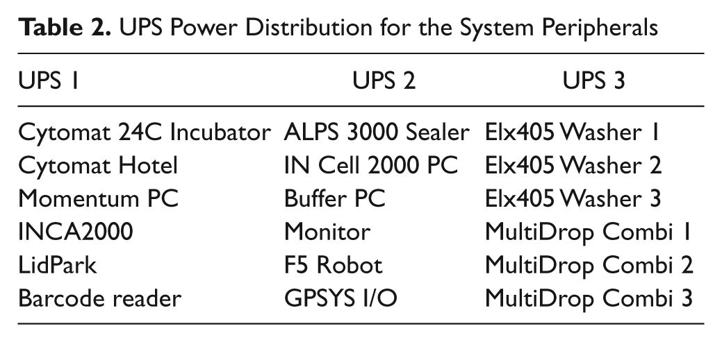
The power distribution ( Table 2 ) of the HCS platform is shared by three uninterruptible power supplies (UPS; American Power Conversion, West Kingston, RI), which are constantly monitored by the dynamic scheduler software. In an event of emergency, it maintains the system operational, allowing the robotic arm to reach a safe location and send a system status notification. These UPS protect all peripherals from surges, spikes, lightning, and other power disturbances. They also prolong the battery life by regulating the charge voltage according to battery temperature.
UPS Power Distribution for the System Peripherals
Dynamic Scheduler
The robotic platform is under the control of Momentum 2.0.1 dynamic scheduler running within the .Net 3.0 environment on a Windows XP operating system. There are two modes in which the scheduler is used to screen, single or multiple modes. A single campaign consists of running only one experiment process, as an example: using the INCA2000 ( Fig. 4A ). A multimode campaign consists of running two or more processes at the same time. The robustness of the dynamic scheduler has proven to be very effective while running both microscopes independently or simultaneously as well as fixing and staining sample plates in parallel. The fixing and staining process consists of pooling all ELx405 Washers and MultiDrop Combis to achieve the highest throughput while using all available instruments. The pooling process, offered by Momentum 2.0.1, is accomplished using the built-in logic and creating a multistep workflow ( Fig. 4B ). Without the built-in logic, the INCA3000 could not properly function with the HCS platform. The flat-field correction task of adjusting for varying intensity on the INCA3000 needs to take place every three sample plates ( Fig. 4C ) during a run. Using a fluorescent dye plate, located on a permanently mounted nest, on top of the INCA3000, the flat-field correction is performed by moving the fluorescent dye plate to the stage nest, using Momentum to run the flat-field correction step, and continuing to run the sample plates thereafter.
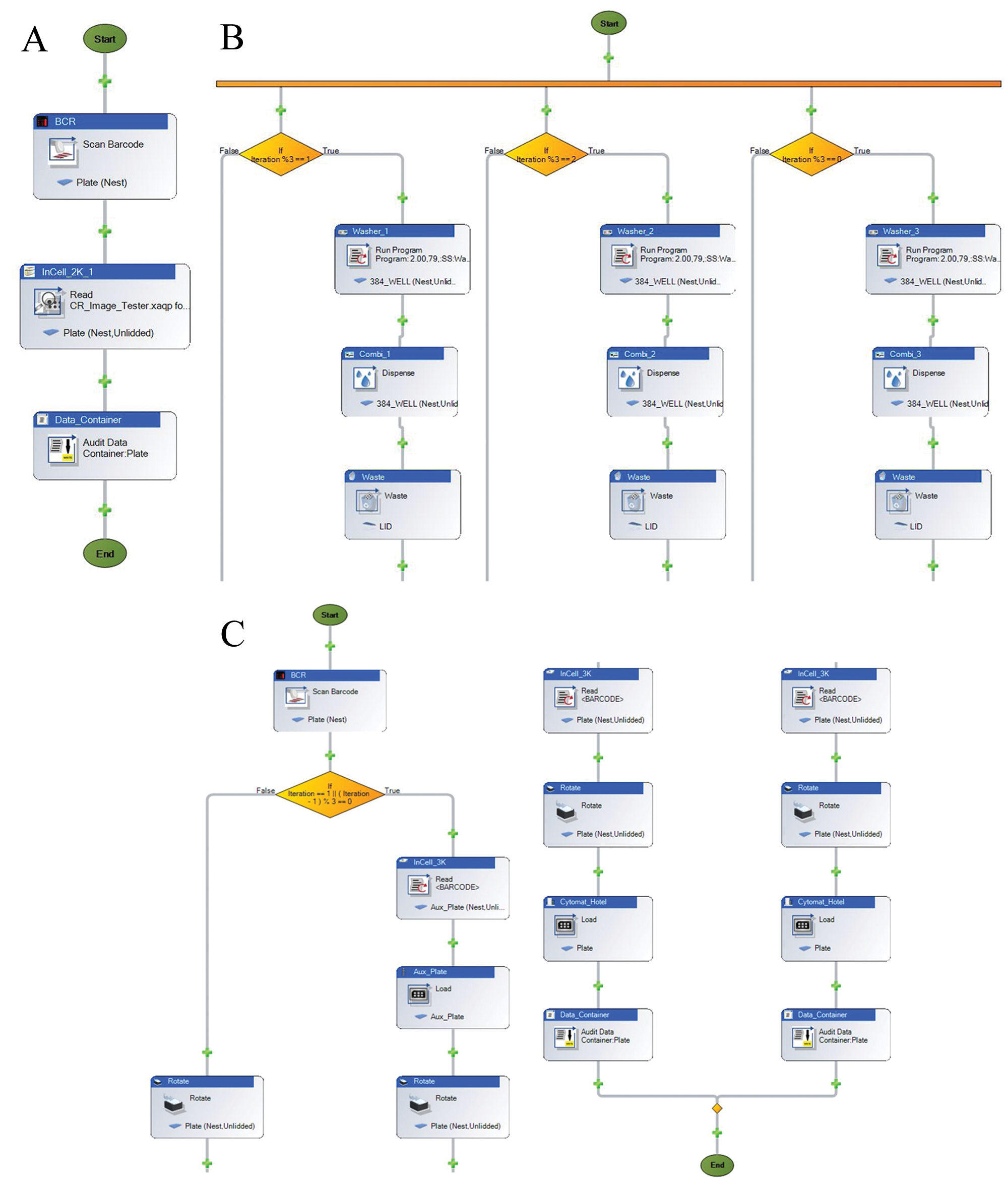
Momentum sample runs. (
Gripper Concept
Accessing the onboard INCA3000 stage nest ( Fig. 5 ) with a standard gripper ( Fig. 6A ) on the F5 robotic arm was a nonattainable task due to the various obstacles on the path to the nest location. A unique gripper concept ( Fig. 6B ) was specially designed and built to access the onboard INCA3000 stage nest. The new gripper concept was built at a 34° angle ( Fig. 6C ), allowing for clearance and accessibility to the INCA3000 stage nest ( Fig. 6D ). The orientation of the sample plate entering the INCA2000 or the INCA3000 stage nests needs to be in portrait orientation. To correctly position the sample plates into the nests of the INCA2000 and the INCA3000 and steer clear of any obstructions, the sample plates can be gripped only from the back end of the plate. Part of the optimizing process of the HCS platform was to limit the plate movement on the system by eliminating a regrip step, portrait-center to portrait-back, while accessing the INCA2000 and INCA3000. As a result, all portrait locations—the Cytomat 24C, Cytomat Hotel, and regrip stations—were taught to hold the sample plates from the portrait-back location. To eliminate any potential issues of dropped plates during the fast movements of the F5 robotic arm, serrated jaws were mounted on the grippers. For optimal plate movement, serrated jaws hold the sample plate more securely in place as opposed to using the two-pins option. The depth clearance of the custom gripper was more than 98 mm, clearing all obstacles and safely accessing the INCA3000 stage nest ( Fig. 7A , B ) while maintaining accessibility to all peripheral nest locations ( Fig. 8 ).
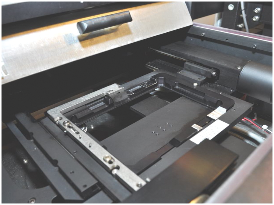
Alpha IN Cell Analyzer 3000 Stage. INCA3000 stage nest dimensions: reachable depth, 61 mm; length from panel to nest, 107 mm; with various obstacles on the path to the stage nest location.
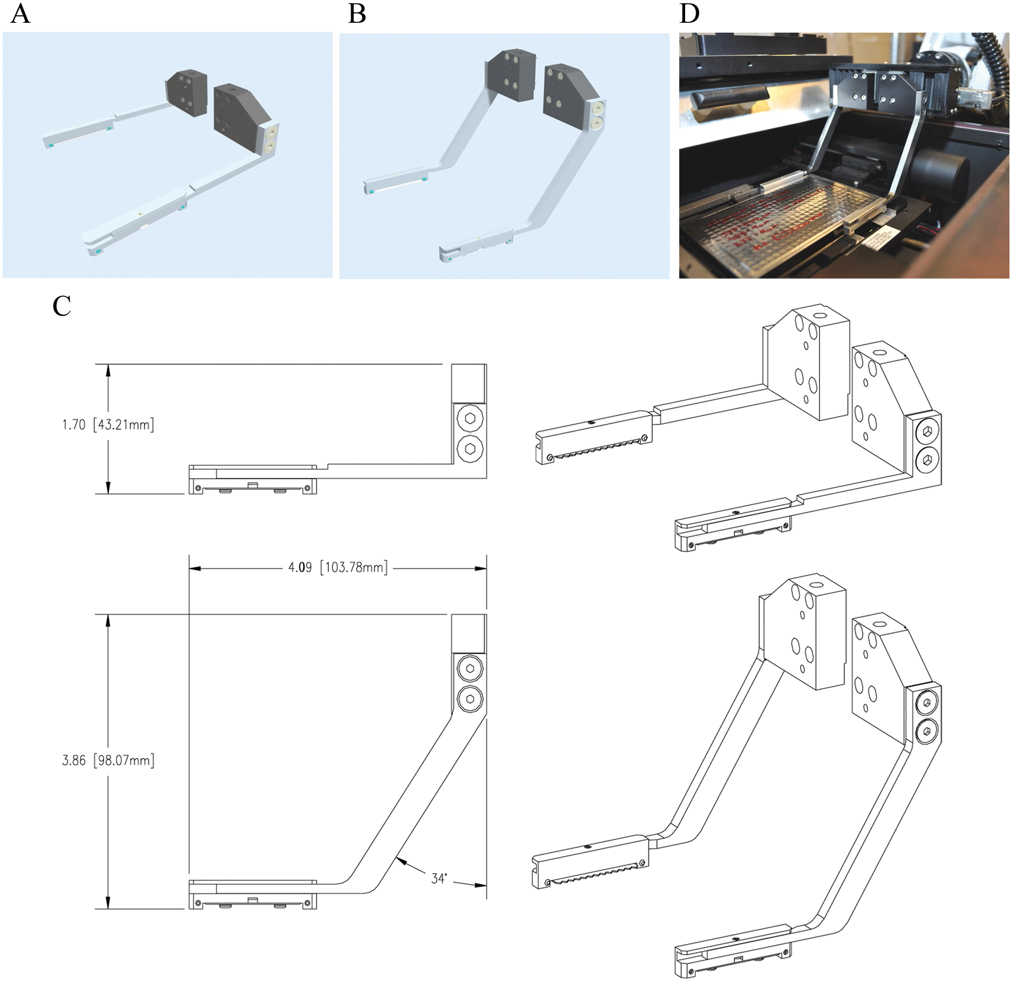
Gripper design. (
Hestia on INCA3000. (
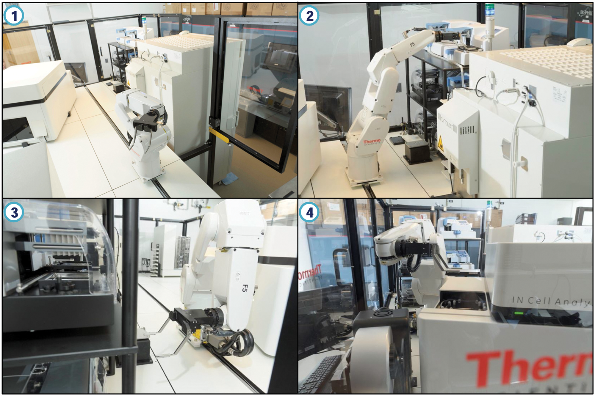
Hestia in motion. 1, Track view of west end of the platform, showing the INCA2000, Cytomat 24C, and the Washer/Combi section; 2, Hestia accessing a top-positioned MultiDrop Combi; 3, Hestia accessing a ELx405 Washer; 4, Hestia accessing the INCA2000 stage nest.
Conclusion
Automation strategies vary in nature because of the intended biologies to be performed on the systems and more often are faced with static challenges such as building code requirements and fixed instrument positions (e.g., heavy instruments). Achieving the intended goals of the project called for out-of-the-box thinking and involved three main stakeholders, namely, MSKCC, GE Healthcare, and Thermo Fisher Scientific. Each is dependent on the other, especially when dealing with the automation of the alpha INCA3000 unit, the first of its kind, as it represented the main “Go/No Go” decision to execute on the project—a perfect example of supplier and integrator working together toward achieving the customer’s automation goals. The final system, Hestia, with newly designed gripper fingers on a CRS F5 robotic arm, met all feasibility requirements to be dedicated to HCS of live and fixed cells; its inauguration back in February 2011 involved four RNAi screening campaigns and for the first time running both the on-board INCAs simultaneously and fully automated. Hestia is the vanguard of the HCS discovery process, with the only fully functional and automated alpha INCA3000 unit in the world.
Footnotes
Acknowledgements
The authors wish to thank Mr. Stephen Egan, director of laboratory operations at MSKCC, and his diligent team for the support provided during the preparation of the laboratory space and for navigating the equipment to a staging area prior to installation. The authors also wish to thank Mr. Leighton Howells of GE Healthcare for all his efforts during the automation process of the alpha INCA3000 unit, Dr. Hansjoerg Haas and Ms. Grace Mangialardi of Thermo Fisher Scientific for their support during the course of the project, and, finally, the members of the HTS Core Facility for their continued support, especially Dr. Christophe Antczak for critically reading the manuscript.
Authors’ Note
Messrs. Ab Alamir, Ian Hatherley, and Trung Trinh are employees of Thermo Fisher Scientific.
Declaration of Conflicting Interests
The authors declared no potential conflicts of interest with respect to the research, authorship, and/or publication of this article.
Funding
The authors disclosed receipt of the following financial support for the research, authorship, and/or publication of this article: The HTS Core Facility is partially supported by the Mr. William H. Goodwin and Mrs. Alice Goodwin and the Commonwealth Foundation for Cancer Research, the Experimental Therapeutics Center of the Memorial Sloan-Kettering Cancer Center, the William Randolph Hearst Fund in Experimental Therapeutics, the Lillian S. Wells Foundation, and NIH/NCI Cancer Center Support grant 5 P30 CA008748-44.